Download to read offline

![Antenna
Antennas are very important for the overall wireless system performance, and there
are many different types.
An antenna is the structure associated with the region of transition from a guided
wave to a free space wave, radiating RF energy.
Antenna features:
frequency range (bandwidth)
Radiation pattern (beamwidth, sidelobes,
backlobe, front-to-back ratio, location of
nulls)
Maximum gain
Input impedance
Physical size and wind resistance
Cost
The directivity of an antenna is simply the ratio of the maximum power density to
the average power density.
D[dBi] = 10log10 (Pmax / Pav)
The gain is closely related to directivity: in this case you have to take into account
the efficiency η of the antenna:
G[dBi] = 10log10 η(Pmax / Pav)
Typical efficiency is between 0.5 and 0.9, depending on the quality of the
construction and the conductivity of the metal used.
Use high gain antennas to reach long distances, and omni or sectorial antennas to
cover wide areas.
Figure: Wind Load](https://image.slidesharecdn.com/301459b5-ed84-426a-8b99-8661e658c48f-170125040840/85/Communication-Engineering-9-320.jpg)

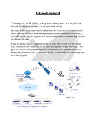
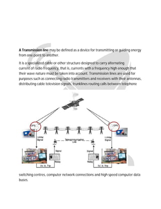
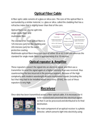
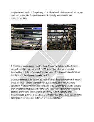
This document discusses transmission systems in satellite communications. It begins by defining a transmission line as a device that transmits or guides energy from one point to another. It then discusses how transmission lines carry alternating current and are used to connect radio transmitters and receivers. The document goes on to describe the key components of fiber optic and wireless transmission systems, including transmitters, receivers, optical fiber cables, antennas, and amplifiers. It explains how each component functions and its role in transmitting signals across long distances.