1. Experimental Stress Analysis
Department of Mechanical Engineering Page 1
Unit 8: Moire’s Methods
Moire’s fringe produced by mechanical interference:
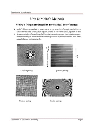
Moire’s fringes are produce by arrays, these arrays are series of straight parallel lines, a
series of radial lines coming from a point, a series of concentric circle, a pattern of dots.
Arrays consisting of straight parallel lines having nontransparent bars with transparent
interspaces of equal width are most commonly used for experimental work. Such arrays
are called grids, gratings or grills.
Circular grating parallel gratings
Crossed grating Radial gratings
2. Experimental Stress Analysis
Department of Mechanical Engineering Page 2
Arrays having up to about 4 lines per cm are called grids.
Arrays having from 20 to 400 lines per cm are called gratings.
Two mutually perpendicular line arrays are termed as cross gratings.
Generally having up to 200 lines per cm are most commonly used in this method.
Two lines grating used in the strain analysis are, the model or specimen grating and
master or reference grating.
Model grating can be applied by coating the specimen with a photographic emulation.
Master grating by bonding, ruling or etching.
The model grating deforms with the test specimen where as the master grating doesn’t
deforms during test.
The distance between the master grating lines is called the pitch P.
The center to center distance on the model grating after deformation will be denoted by
P’.
3. Experimental Stress Analysis
Department of Mechanical Engineering Page 3
By interfacing the two gratings a pattern of fringes is produced.
The distance between the fringes is called fringe spacing and is denoted D.
Any line perpendicular to master grating line will be called the principal direction and a
line parallel to master grating line will be called secondary direction.
When the grating are superimposed one against the other that produces Moirés fringes,
either their having a difference in pitches, or difference in orientation.
The dark fringes will appear at the point where the non-transparent strip falls over a
transparent strip.
When two non transparent strips overlap it produces light fringe.
For identification purpose, we shall denote the center lines of the dark lines of gratings
with number 0 to m for one and 0 to n for the other, and the center lines of the light
fringes will be denoted by number o to N, where N is the fringe order.
The fringe order N and the parameters m and n identifying the lines of the two interfering
gratings must satisfy an identical equation which is,
∓ =
The family of Moire’s fringes for which the equation m-n=N is valid is the subtractive
Moire’s pattern, while the family of Moire’s fringes for which the equation m+n=N is
valid is called the additive Moire’s fringe.
Moiré’s fringe analysis techniques
Two different approaches are used in order to obtain strains by the Moire’s method. One is called
the geometrical and other consists in relating the fringes to the displacement field.
Geometrical approach
Moire’s fringes are formed by two interfering lines screens or gratings. One is the printed in the
model(model grating) is subjected to deformations produced by applied loads. The second(
master grating) is applied on the top of the first. The pitch of the model and master gratings is
assumed to be the same before application of the load. When the load is applied to the specimen
the model grating deforms and gives rise to Moire’s interference fringes which can be studied for
strain analysis. Knowing the distance between the master lines and measuring the distance
between the fringes, it is possible by geometric analysis of the intersections of the two system of
lines to compute the distance between the model grating line at a point, and the corresponding
change in direction. With these data , normal and shear strains can e computed.
4. Experimental Stress Analysis
Department of Mechanical Engineering Page 4
Let p= pitch of the master grating which is also equal to the pitch of the model grating before
deformation.
P’= pitch of the model grating after deformation.
q= specimen grating orientation angle measured from the reference grating line to the specimen
grating line positive if counter clockwise.
d= interfringe spacing, i.e the perpendicular distance between two neighboring fringes.
It is assume that before deformation orientation of specimen grating is same as master grating.
From triangle ABM
∅ −
2
=
=
∅
= ∅
……(a)
From triangle ABC
∅ −
2
− =
′
=
′
∅
=
′
(∅ )
……(b)
From equation a and b
5. Experimental Stress Analysis
Department of Mechanical Engineering Page 5
′
sin(∅ − )
=
sin∅
′
=
(∅ )
∅
…………… (1)
We know that BF
From triangle BDE
sin =
= …….(c)
From triangle BDF
∅ −
2
− =
δ
=
δ
sin(∅− )
…....(d)
From equation c and d
sin
=
δ
sin(∅ − )
δ = sin
sin(∅ − )………(2)
δ
=
sin(∅ − )
sin
δ
=
sin ∅ cos − sin cos∅
sin
δ
= sin ∅ cot − cos∅
δ
+ cos∅ = sin ∅
1
tan
tan =
∅
∅
….....(3)
6. Experimental Stress Analysis
Department of Mechanical Engineering Page 6
Equation 2 can be written as
sin(∅ − ) = sin ……(4)
Substitute eq 4 in eq 1
′
=
sin ∅
δ
sin
′
=
δ
∅
sin ….(5)
′
=
δ
sin ∅
sin
cos
cos
′
=
δ
sin ∅
tan
1
sec
′
=
δ
∅
tan
√
……(6)
Substitute eq 3 in eq 6
′
=
δ
sin ∅
sin ∅
δ
+ cos ∅
1
1 +
sin ∅
δ
+ cos ∅
′
=
δ
δ
+ cos ∅
δ
+ cos ∅
δ
+ cos ∅ + 2
δ
cos ∅ + sin ∅
′
=
δ
δ
+ 1 + 2
δ
cos ∅
7. Experimental Stress Analysis
Department of Mechanical Engineering Page 7
Once the deformed specimen pitch p’ has been determined the component of normal strain in a
direction perpendicular to the lines of the master grating can e computed as
=
′ −
Displacement approach
A Moire’s fringe is a locus of points having the same magnitude of displacements in the
principal direction of master grating. Such a locus is called an isothetic. Therefore, a Moire
fringe, an isothetic pattern, can be visualized as a displacement surface where the height of a
point on the surface above a reference plane represents the displacement of the point in the
principal direction of master grating. Two isothetic patterns are obtained using gratings
perpendicular ti x-axis and y-axis, respectively, on the surface of a specimen under investigation.
From these moiré gratings u and v displacements are determined by noting down the order of
fringes Nx and Ny
Then
=
= ……….. (1)
The Cartesian components of strain can be computed from the derivatives of displacements as
follows:
=
= …………………. (2)
= +
The slope of displacements as above are obtained by drawing tangents to the displacement
curves of u and v fields along x and y axis.
Fig 1(a) shows the Moire fringes when the model grating is perpendicular to x-axis. Order of the
fringes Nx, are marked as shown(fig.1a).
8. Experimental Stress Analysis
Department of Mechanical Engineering Page 8
Lines along x and y axis say AB and CD are drawn. The displacement u along AB and CD are
plotted by noting that
=
Where p is pitch of the master grating.
Now fig shows the moiré fringes when the model grating is perpendicular to y-axis. Order of the
fringes Ny are marked as shown. Line AB and CD along x and y axes are drown. The
displacement v along AB and CD is plotted by noting that
=
Where ‘p’ is the pitch of the master grating. From the plots of u versus y, v versus x, and v
versus y, strains at any point are determined by using the relationships given by eq 2.
When the strains are large, then
= 1 + 2 + + + − 1
= 1 + 2 + + + − 1
= sin
⎣
⎢
⎢
⎡ + + +
(1 + ) 1 +
⎦
⎥
⎥
⎤
9. Experimental Stress Analysis
Department of Mechanical Engineering Page 9
Out of plane displacement measurement
In certain plane stress problems and in a wide variety of problems involving laterally loaded
plates, out of plane displacements ω becomes important considerations. A Moire’s method for
determining out of plane displacements has been developed.
For out of plane displacement measurements, a master grating is employed in front of the
specimen, and a collimated beam of light is directed at oblique incidence through the master
grating and onto the surface of the specimen, as shown in fig. the shadow of the master grating
on the surface of the specimen serves as the specimen grating. When the specimen is viewed at
normal incidence, Moire’s fringes form as a result of interference between the lines of the master
and the shadows. Use of a matte surface to ensure distinct shadows improve the quality of the
Moire’s fringe patterns.
From fig it can be seen that the difference in distance between the master grating and the
specimen surface at two adjacent fringe locations can be expressed as
− =
tan
Where p is the pitch of the master grating and is the angle of incidence of the collimated light
beam.
10. Experimental Stress Analysis
Department of Mechanical Engineering Page 10
In practice, the master grating is located a small distance away from the specimen to
accommodate any surface displacements toward the master grating and to serve as a datum plane
for the measurement of load-induced, out of plane displacements. Any distribution of Moire’s
fringes appearing with the master grating in this initial position will represent irregularities in the
surface of the specimen. The presence of any irregularity must be accounted for in the final
determination of the out of plane displacement.
If a point of zero out-of-plane displacement is known to exist at some point in the specimen, the
master grating can be positioned to locate a Moire fringe over this point. At all other fringe
locations, the out-of-plane displacement ω can then be expressed as
=
tan
Where n is the order of the Moire’s fringe at the point.
Out of plane slope measurement/ Ligtenberg method
The out of plane displacement measuring technique provide the required curvatures for a
solution to the stress problem. In practice, the double differentiations cannot be performed with
sufficient accuracy to provide suitable values for the curvatures. To overcome this experimental
difficulty, Ligtenberg has developed a Moire method for measuring the partial slope ⁄ and
⁄ . A single differentiation then provides reasonably accurate values for the required
curvature.
The essential features of the Ligtenberg method are as shown in fig. the equipment consists of a
fixture for holding and loading the plate, a large cylindrical surface with a coarse line grating,
and a camera for recording the Moiré’s fringe patterns. The surface of the plate is made
reflecting since the camera views the image of the grating on the surface of the plate. Since the
image does not depend on the angle of incidence of the light, a collimated beam is not required
for this method. The moiré fringe pattern is formed by superimposing grating images before and
after loading.
From the fig it can be seen that the location on the grating being viewed by the camera, as a
result of reflections from a typical point P on the surface of the specimen, shifts as the plate
deflects under load. the Moire fringe pattern formed by the superposition of the images provides
a measure of this shift. Shift can be expressed in terms of the local slope of the plate as
= 2
Where s= magnitude of shift
= local slope of plate in a plane perpendicular to un-deformed plate and lines of grating
11. Experimental Stress Analysis
Department of Mechanical Engineering Page 11
d= distance between plate and grating
A Moire fringe will form upon superposition of the two images if the shift s is equal to the pitch
p of the grating. Thus the order of the Moire fringe can be expressed as
=
2
=
2
The distance d should be large to minimize the effects of plane displacements on the shift
distance s.
The angle given by eq 2 is the partial slope ⁄ or ⁄ depending on the orientation of
the grating. Two Moire patterns of this slope will be needed to solve a plate problem completely.
The two patterns can be obtained by rotating the grating 90 deg after the first pattern is recorded.