Basic Electronics for diploma students as per technical education Kerala Syll...
experimental stress analysis-Chapter 2
1. Experimental Stress Analysis
Department of Mechanical Engineering Page 1
Strain Analysis Method
Introduction:
For completely defining the strain or stress at a point on the surface of a component or structure,
generally it is necessary to measure strains along three different directions at that point. Multiple
element strain gauges or rosettes with strain gauges oriented along fixed directions are used for
this purpose.
When both the magnitude and directions of the principal strains at a point are unknown, a three
element strain gage is needed for the complete definition of strain at that point. Consider the case
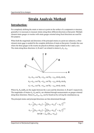
where the three gauges in the rosette are placed at arbitrary angles related to the x-and y axis.
The strain along these directions A, B and C are related to strains ∈ ,∈ ,
∈ =∈ +∈ + sin cos
∈ =∈ +∈ + sin cos
∈ =∈ +∈ + sin cos
Where , and are the angles between the x-axis and the directions A, B and C respectively.
The magnitudes of strains ∈ , ∈ and ∈ are obtained through measurements on gauges oriented
along these directions. Hence ∈ ,∈ , can be found out by solving the simultaneous eq
The principal strains and principal directions are then determined through
∈ =
1
2
∈ +∈ +
1
2
∈ −∈ +
⁄
∈ =
1
2
∈ +∈ −
1
2
∈ −∈ +
⁄
tan2∅ = ∈ −∈⁄
2. Experimental Stress Analysis
Department of Mechanical Engineering Page 2
Here ∅ is the angle between the x axis and the principal axis corresponding to strain ∈ . From
the principal strains ∈ and∈ , the principal stress and can be determined from
= (∈ + ∈ ) (1 − )⁄
= (∈ + ∈ ) (1 − )⁄
Several multiple element rosettes with gauges oriented along specified directions are
commercially available. These rosettes are denoted by the angles along which the gauges are
oriented in them as the three element rectangular rosettes, delta russets, four element rectangular
rosettes and tee-delta rosette.
Two element rectangular rosettes:
This rosette is suitable only when the directions of principal strain are known. The gage a is
arranged along the maximum strain direction chosen along the x-axis so that = 0 and the gage
b is set along the minimum strain direction so that = 90
Fig: Two gage rosette
The strain along these directions A, B is
∴ ∈ =∈
∈ =∈
Hence, ∈ = ∈ , ∈ = ∈ , = (∈ − ∈ )
The principal stress and can be
= (∈ + ∈ ) ∗
(1 − )
= (∈ + ∈ ) ∗
(1 − )
3. Experimental Stress Analysis
Department of Mechanical Engineering Page 3
=
2(1 + )
(∈ − ∈ )
Three element rectangular rosettes:
In this rosette the three gage are laid out so that the axis of gauges B and C are at 45o
and 90 o
respectively to the axis of gage A. taking the OA axis to be coincident with the O x-axis, the
angles corresponding to the gauges A, B and C in the three- element rectangular rosette are
= 0 = 45 = 90
Than
∴ ∈ =∈ …………………………….. (1)
∈ =
1
2
∈ +∈ + … … … … … … … (2)
∈ =∈ … … … … … … … … … … … … … . (3)
We can rewrite these eq in terms of∈ , ∈ , are obtained as
∴ ∈ =∈
∈ =∈
= 2 ∈ − ( ∈ + ∈ )……………… (4)
The principal strains are given by
∈ =
1
2
∈ +∈ +
1
2
∈ −∈ +
⁄
∈ =
1
2
(∈ +∈ ) +
1
2
(∈ −∈ ) + 2 ∈ − ( ∈ + ∈ )
⁄
4. Experimental Stress Analysis
Department of Mechanical Engineering Page 4
∈ =
1
2
∈ +∈ −
1
2
∈ −∈ +
⁄
∈ = (∈ +∈ ) − (∈ −∈ ) + 2 ∈ − ( ∈ + ∈ )
⁄
………………….. (5)
Maximum shear strains
= ∈ −∈ +
⁄
= {(∈ −∈ ) + (2 ∈ −∈ −∈ ) } ⁄
……………… (6)
Principal strain directions are
tan2∅ = ∈ −∈⁄
tan 2∅ = [ 2 ∈ − ∈ − ∈ ] (∈ −∈ )⁄ ……. (7)
Substituting eq 5 value in the general eq of the principal stress and and we get
= (∈ + ∈ ) (1 − )⁄
=
2
∈ +∈
(1 − )
+
1
(1 + )
{(∈ −∈ ) + ( 2 ∈ − ∈ − ∈ ) } ⁄
= (∈ + ∈ ) (1 − )⁄
=
2
∈ +∈
(1 − )
−
1
(1 + )
{(∈ −∈ ) + ( 2 ∈ − ∈ − ∈ ) } ⁄
Maximum shear stress is given by
=
2(1 + )
=
2(1 + )
{(∈ −∈ ) + (2 ∈ −∈ −∈ ) } ⁄
Three element delta rosettes:
In a three element delta rosette three gauges are placed at angular disposition of 0o
,120o
, 240o
.
for a delta rosette,
10. Experimental Stress Analysis
Department of Mechanical Engineering Page 10
= ∈ −∈ +
⁄
= (∈ −∈ ) +
4
3
(∈ −∈ )
⁄
Maximum shear stress is given by
=
2(1 + )
=
2(1 + )
(∈ −∈ ) +
4
3
(∈ −∈ )
⁄
Transverse sensitivity error in rosettes:
In the analysis presented above the strain gage readings were assumed to be free from errors due
to transverse sensitivity effects. However, in actual practice the effect of transverse sensitivity
should be studied while measuring the stresses in a biaxial stress field with strain gauges. If it is
found that the error due to transverse sensitivity effect is significant, the strain gage readings
should be corrected for it.
Two element rectangular rosette:
Consider first a two-element rosette, with the gage axes aliened with two perpendicular axes x
and y on the test surface. It is assumed that the individual gage elements in the rosette have the
same transverse sensitivity.
Where∈ and ∈ are strains indicated by gauges along x and y directions respectively. ∈ and
∈ are the corresponding corrected strains.
∈ =
1 −
1 −
∈ − ∈
∈ =
1 −
1 −
∈ − ∈
The equations given above are for the gage elements oriented along any two orthogonal axes, x
and y. in actual practice the two element rectangular rosette is generally used with the axes of the
gage oriented along the principal axes. In such case x and y axes would denote the principal
axes.
∈ =
1 −
1 −
(∈ − ∈ )
11. Experimental Stress Analysis
Department of Mechanical Engineering Page 11
∈ =
1 −
1 −
(∈ − ∈ )
Three element rectangular rosette:
The individual strain readings,∈ , ∈ , ∈ , of a three element rectangular rosette can be corrected
for transverse sensitivity effects as follows. The corrected strains∈ , ∈ along the orthogonal
axes A and B respectively are
∈ =
1 −
1 −
(∈ − ∈ )
∈ =
1 −
1 −
(∈ − ∈ )
From the condition (∈ +∈ ) is an invariant, the strain along axis D orthogonal to axis B can be
estimated as
∈ =∈ +∈ −∈
Substituting the orthogonal strains∈ and ∈ , the corresponding strain ∈ is obtained.
∈ =
1 −
1 −
∈ − (∈ +∈ −∈ )
The corrected strains are used along with equations given to determine the principal strains,
stress and principal directions.
Three element delta rosette:
Expressions for correcting individual strain readings from a delta rosette for transverse
sensitivity effects can be easily derived for the case where all the three gage element have the
same transverse sensitivity k.
∈ =
1 −
1 −
1 +
3
∈ −
2
3
(∈ +∈ )
∈ =
1 −
1 −
1 +
3
∈ −
2
3
(∈ +∈ )
∈ =
1 −
1 −
1 +
3
∈ −
2
3
(∈ +∈ )
12. Experimental Stress Analysis
Department of Mechanical Engineering Page 12
Shear strain gauges:
Strain gauges do not respond to shear strains. However the relationship between shear and
normal strains can be utilized to obtain from a strain rosette an output directly proportional to the
shear strain in the surface.
The two strain gauges a and b oriented so that the x axis bisects the angle between the gage axes.
Strain along two gage axes is
∈ =
∈ +∈
2
+
∈ −∈
2
cos2 +
2
sin 2
∈ =
∈ +∈
2
+
∈ −∈
2
cos2 −
2
sin 2
From the above eq. The shear strain is
=
∈ −∈
sin 2
From above eq the difference in the normal strain sensed by any two arbitrarily oriented gauges
in a uniform strain field is directly proportional to the shear strain along an axis bisecting the
included angle between the strain gage axes. When the included angle is 900
, i.e. the rosette is a
two-element rectangular rosette, above eq can be reduced to
=∈ −∈
Hence by orienting a two-element rectangular rosette such that the x-axis bisects the 900
angle
between the gage elements and connecting the gage elements in the adjacent arm of a
Wheatstone bridge, an output from the rosette equal to the shear strain can be obtained
directly.
13. Experimental Stress Analysis
Department of Mechanical Engineering Page 13
Stress gauges:
In some application it may be desirable to have an output from a single strain gage directly
proportional to the axial stress in a particular direction. Such gauges are known as stress gauges.
For eg, if one wishes to determine the stress at say, five stations along specified directions under
dynamic loading, the use of stress gage in place of strain rosettes results in considerable saving
in equipment. The principle of operation of a stress gage is given below.
Stress gauge
Mohr’s circle of strain
14. Experimental Stress Analysis
Department of Mechanical Engineering Page 14
Fig 1 shows the sketch of a stress gage with its axis along the x-axis. The gage is oriented such
that the x-axis bisects the angle 2 between the grid elements A and B of this gage.
The strains along the grid elements A and B are given by
∈ = ( + ) + ( − ) 2( − )…………. (a)
∈ = ( + ) + ( − ) 2( + )………… (b)
The average of these will be
∈ +∈ = ( + ) + ( − )[ 2( + ) + 2( − )]…………. (c)
On expanding the cosine terms in above eq
∈ +∈ = ( + ) + ( − ) 2 2 …………. (d)
From Mohr’s strain circle
∈ +∈ =∈ +∈ ………..... (e)
∈ −∈ = (∈ −∈ )cos2 ………. (f)
Substituting the values in eq e and f in eq d and simplifying
1
2
∈ +∈ =
1
2
+ +
1
2
− 2
1
2
∈ +∈ =
1
2
+ +
1
2
− (2 − 1)
1
2
∈ +∈ =
1
2
+ + − −
1
2
−
1
2
∈ +∈ = − +
1
2
∈ +∈ = + (1 − )
1
2
∈ +∈ = +
∈ +∈ = + ……………….(g)
If is so chosen that it is equal to tan √ then
=
15. Experimental Stress Analysis
Department of Mechanical Engineering Page 15
=
=
w.k.t
1 = +
Substituting the value of in above eq
(1 + ) = 1
= ……………. (h)
Substituting these values in eq g yields
∈ +∈ = + …………….. (i)
However,
= ∈ + ∈ ………(j)
Substituting the values of ∈ + ∈ from eq I and j gives
= ∈ +∈ ………………. (1)
It may be noted that ∈ +∈ is the strain indicated by the stress gage, i.e.
( ⁄ )
. thus
the stress along the x-axis is obtained by multiplying the strain indicated by the stress gage
with /(1 − ) .
If the direction of the maximum principal stress is known, a single conventional strain gage
can be used as shown in fig 3 to directly measure the principal stress . In this case as is zero
from eq a and b,
∈ =∈ =∈ ……… (k)
Substituting this condition in eq 1 gives
= = ∈ ………. (2)
Hence to measure the principle stress it is only necessary to orient a single strain gage
along = tan √ a direction at an angle to the axis and multiply the strain gage reading by
.