Flowchart of sequences
•Download as PPTX, PDF•
0 likes•213 views

Applied fluids and hydraulics final project

Recommended
More Related Content
What's hot
What's hot (20)
Viewers also liked
Viewers also liked (18)
Similar to Flowchart of sequences
Similar to Flowchart of sequences (20)
More from Joseph Legan
More from Joseph Legan (20)
Recently uploaded
Recently uploaded (20)
Flowchart of sequences
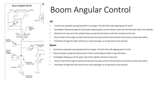
- 1. Boom Angular Control UP • Controls are operated causing Solenoid A to energize. The DCV shifts right aligning ports P and A. • Fluid begins flowing through the Check valve, bypassing the counter balance valve and into the piston side of the cylinder. • Fluid from the rod end of the cylinder flows out and into the B port of the DCV and back to the tank. • Once at limit of the range of motion the pressure increases and the internal pilot of the pressure relief valve opens. • Fluid flows through the Filter and Oil to air heat exchanger on its way back to the reservoir. Down • Controls are operated causing Solenoid B to energize. The DCV shifts left aligning ports P and B. • Pressure builds causing the external pilot of the Counter Balance Valve to open the valve. • Fluid begins flowing out of the piston side of the cylinder and back to the tank. • Once at limit of the range of motion the pressure increases and the internal pilot of the pressure relief valve opens. • Fluid flows through the Filter and Oil to air heat exchanger on its way back to the reservoir.
- 2. Boom and Fork Extension Extension • Controls are operated causing Solenoid A to energize. The DCV shifts right aligning ports P and A. • Fluid flows over the CBV check valve on the piston end of the Boom cylinder while fluid from the rod end flows through the Sequence Valve check valve and back to the B port. • Fluid flows from the T port through the filter and oil to air heat exchanger on it way back to the reservoir. • Once the Boom cylinder reaches full extension the internal pilot of the Sequence Valve opens allowing fluid to flow through the check valve of the CBV and into the piston end of the Fork Cylinder. • Fluid flows from the rod end of the Fork Cylinder and through the Filter and Oil to air heat exchanger on its way back to the reservoir. • Once at limit of the range of motion the pressure increases and the internal pilot of the pressure relief valve opens. • Fluid flows through the Filter and Oil to air heat exchanger on its way back to the reservoir. Retraction • Controls are operated causing Solenoid B to energize. The DCV shifts left aligning ports P and B. • Pressure is applied to the rod end of the Fork Cylinder, this opens the external pilot of the CBV and fluid begins flowing out of the piston end of the cylinder. • Once the Fork Cylinder is fully retracted and the pressure increases opening the Sequence Valve and allowing pressure to be applied to the rod end of the Boom Cylinder. • The pressure opens the pilot of the Boom Cylinder CBV and fluid flows out of the piston end of the cylinder and back to the B port of the DCV. • Fluid flows through the Filter and Oil to air heat exchanger on its way back to the reservoir • Once at full retraction the pressure increases and the internal pilot of the pressure relief valve opens. • Fluid flows through the Filter and Oil to air heat exchanger on its way back to the reservoir
- 3. Fork Angular Control Up • Controls are operated causing Solenoid A to energize. The DCV shifts right aligning ports P and A. • Pressure in applied to the piston end of the cylinder causing the forks tips to rotate up. • Fluid from the rod end of the cylinder flows back to port B, over a filter and back to the tank. • Once at limit of the range of motion the pressure increases and the internal pilot of the pressure relief valve opens. • Fluid flows through the Filter and Oil to air heat exchanger on its way back to the reservoir. Down • Controls are operated causing Solenoid B to energize. The DCV shifts left aligning ports P and B. • Pressure in applied to the rod end of the cylinder causing the forks tips to rotate down. • Fluid from the piston end of the cylinder flows back to port A, over a filter and back to the tank. • Once at limit of the range of motion the pressure increases and the internal pilot of the pressure relief valve opens. • Fluid flows through the Filter and Oil to air heat exchanger on its way back to the reservoir.