SlideShare a Scribd company logo
1 of 7
Download to read offline
© 2012, The Fiber Optic Association, Inc. Cable plant loss FOA-1a.doc, 11/15/14, 1
FOA Standard FOA-1
Testing Loss Of Installed Fiber Optic Cable Plant
This test will measure the loss of an installed fiber optic
cable plant, singlemode or multimode, including the loss of
all fiber, splices and connectors.
Equipment Needed To Perform This Test
1. Test source appropriate for the fiber being tested
(Multimode: 850 and/or 1300nm LED, singlemode,
1310 and/or 1550 nm laser)
2. Optical power meter calibrated at the same
wavelengths as the source output.
3. Launch and receive reference cables of the same
fiber type and size as the cable plant and have
connectors compatible to those on the cable plant.
They should be tested per FOA-2 to ensure they are
in good condition.
4. Mating adapters compatible to connectors
5. Cleaning supplies
Test Diagram
Test Procedure
1. Turn on equipment and allow time to warm-up
2. Attach launch cable to source. This should remain
connected to source for the duration of the test.
3. Clean all connectors and mating adapters.
4. Set “0 dB” reference using method shown to the
right. Meter may be set to read “0 dB.”
5. Attach source/ref cable and meter/ref cable to the
cable plant under test and make loss measurement.
Options For “0 dB Reference” - Set Before Testing
1. Use the “1 Cable Reference” if connectors are the
same on the cable plant as the testers and
reference cables or may be adapted using hybrid
adapters.
2. Use the “2 Cable Reference” if connectors are not
the same on the cable plant as the testers but can
be mated to each other with adapters and hybrid
reference cables are being used.
3. Use the “3 Cable Reference” if connectors are
plug/jack styles and reference cables are both
ended in either plugs or jacks.
Reducing Measurement Uncertainty
1. Clean all connectors regularly before and while
testing.
2. Use modal control on launch cable, e.g. small loop
on SM fiber or mandrel wrap on MM fiber.
3. Check “0 dB Reference” periodically during testing.
4. 4. Periodically check reference cables per FOA-2 to
verify their condition.
Documentation
Record the date of the test, operator, test equipment used,
reference method, cable and fiber identification, test
wavelength and measured loss.
Setting “0 dB” Reference
1 Cable Reference
2 Cable Reference
3 Cable Reference
© 2012, The Fiber Optic Association, Inc. Patchcord and Cable loss FOA-2.doc, 11/15/14, 1
FOA Standard FOA-2
Testing Loss Of Fiber Optic Cables, Single-Ended
This test will measure the loss of a fiber optic cable,
singlemode or multimode, including connectors on each end
individually. For short cables, e.g. patchcords, with negligible
fiber loss, the measured loss may be considered the loss of
the connector mated to the reference connector.
Equipment Needed To Perform This Test
1. Test source appropriate for the fiber being tested
(Multimode: 850 and/or 1300nm LED, singlemode,
1310 and/or 1550 nm laser)
2. Optical power meter calibrated at the same
wavelengths as the source output with adapters to
mate to connector type on cable.
3. Launch reference cable that is the same fiber type
and size as the cable plant and have connectors
compatible to those on the cable.
4. Mating adapters compatible to connectors
5. Cleaning supplies
Test Diagram
Test Procedure
1. Turn on equipment and allow time to warm-up
2. Attach launch cable to source. This should remain
connected to source for the duration of the test.
3. Clean all connectors and mating adapters.
4. Set “0 dB” reference using method shown to the
right. Meter may be set to read “0 dB.”
5. Attach source/ref cable and to the cable under test
and make loss measurement.
6. Reverse cable and test again.
Options For Testing With Different Connector Types
1. If the connector(s) on the cables to test are “plug
and jack” type and/or are not compatible to the
optical power meter for testing and/or reference, you
cannot test single-ended. Use the FOA-1 method
with a 2 or 3 Cable Reference as appropriate.
Results will include loss of connectors on both ends.
Reducing Measurement Uncertainty
1. Clean all connectors regularly before and while
testing.
2. Use modal control on launch cable, e.g. small loop
on singlemode fiber or mandrel wrap on multimode
fiber.
3. Check “0 dB Reference” periodically during testing.
Documentation
Record the date of the test, operator, test equipment used,
reference method, cable and fiber identification, test
wavelength and measured loss.
Setting “0 dB” Reference
© 2012, The Fiber Optic Association, Inc. Measure Optical Power FOA-3.doc, 11/15/14, 1
FOA Standard FOA-3
Measuring Optical Power In Fiber Optic Systems
This test will measure the optical power exiting the end of
a fiber optic cable. This test is commonly used to
measure the coupled power of a fiber optic source in a
transmitter, power into a receiver or for setting references
for optical loss measurements.
Equipment Needed To Perform This Test
1. Fiber optic power meter calibrated at the same
wavelength as the source output (e.g. multimode:
850 and/or 1300nm, singlemode, 1310, 1490
and/or 1550 nm, POF 650 nm) capable of
measuring optical power in the power range of
the source.
2. Optical power meter adapters to mate to
connector type on cable.
3. Reference cable that is the same fiber type and
size as the cable plant and have connectors
compatible to those on the source and cables.
4. Cleaning supplies
Test Diagram
Test Procedure
1. Turn on meter and allow time to warm-up
2. Set meter to wavelength of source and “dBm” to
measure calibrated optical power.
3. Clean all connectors and mating adapters.
4. Attach reference cable to source if testing source
power or disconnect cable from receiver.
5. Attach power meter to end of cable and read
measured power.
Options For Testing
Power is generally measured in “dBm” or dB
referenced to 1 milliwatt of optical power. Optical
power measurements may also be made in
Milliwatts (mW) or microwatts (µW)
Reducing Measurement Uncertainty
1. Calibrate optical power meter according to
manufacturer specified intervals.
2. Clean all connectors and remove meter adapter
periodically to clean the adapter and power meter
detector.
3. Do not bend fiber optic cables tightly to cause
stress loss.
Documentation
Record the date of the test, operator, test equipment
used, cable and fiber identification, test wavelength and
measured power.
Note:
A reference cable or known good
patchcord is used for testing source
power coupled into a fiber. Receiver
power is tested by disconnecting the
system cable connecting to the receiver
and attaching it to the power meter to
measure power.
©2013, The Fiber Optic Association, Inc. FOA Standard FOA-5 Datalinks.doc 11/15/14 1
FOA Standard FOA-5
Fiber Optic Data Links
Definition
A fiber optic datalink is a communications
subsystem that connects inputs and outputs (I/O)
from electronic subsystems and transmits those
signals over optical fiber. Fiber optic datalinks may
transmit signals that are either analog or digital and
of many different, usually standardized, protocols,
depending on the communications system(s) it
supports.
Components
A fiber optic datalink consists of fiber optic
transceivers or individual transmitters and receivers
at either end that transmit over optical fibers. The
typical datalink transmits over two fibers for full
duplex links, one fiber in each direction. Wavelength
division multiplexing may be used to transmit bi-
directionally on one fiber. The fibers may be of any
type, multimode (graded index or step index) or
singlemode. Distance and bandwidth considerations
may dictate the choice or grade of the optical fiber or
require regeneration.
Performance-Power Budget
All datalinks are limited by the power budget of the
link. The power budget is the difference between the
output power of the transmitter and the input power
requirements of the receiver. The receiver has an
operating range determined by the signal-to-noise
ratio (S/N) in the receiver. The S/N ratio is generally
quoted for analog links while the bit-error-rate (BER)
is used for digital links. BER is basically an inverse
function of S/N.
Testing
Testing the operation of the transceivers with the
cable plant includes optical power testing of the
output of the transmitter and the receiver input
power compared to specifications for the link. FOA
Standards for testing cable plant loss and optical
power can be used to properly specify test
requirements.
After the datalink or communications system is
installed, testing the BER or SNR may also be done
to confirm that the link is operating properly.
Documentation
Datalinks should be included in all systems
documentation, including equipment specifications,
transceiver power levels, lengths and routing, test
results, etc.

More Related Content

What's hot

Optical Amplifier and Networks
Optical Amplifier and NetworksOptical Amplifier and Networks
Optical Amplifier and NetworksJagadish M
 
12 gain flattening in erbium doped fiber amplifier based optical communicatio...
12 gain flattening in erbium doped fiber amplifier based optical communicatio...12 gain flattening in erbium doped fiber amplifier based optical communicatio...
12 gain flattening in erbium doped fiber amplifier based optical communicatio...Arun K Mohan
 
Performance Improvement for Hybrid L-band Remote Erbium Doped Fiber Amplifier...
Performance Improvement for Hybrid L-band Remote Erbium Doped Fiber Amplifier...Performance Improvement for Hybrid L-band Remote Erbium Doped Fiber Amplifier...
Performance Improvement for Hybrid L-band Remote Erbium Doped Fiber Amplifier...IJECEIAES
 
An Overview of EDFA Gain Flattening by Using Hybrid Amplifier
An Overview of EDFA Gain Flattening by Using Hybrid AmplifierAn Overview of EDFA Gain Flattening by Using Hybrid Amplifier
An Overview of EDFA Gain Flattening by Using Hybrid AmplifierIJEEE
 
Optical amplifiers and networking
Optical amplifiers and networking Optical amplifiers and networking
Optical amplifiers and networking Amogha Bandrikalli
 
Comparison among fiber amplifiers
Comparison among fiber amplifiersComparison among fiber amplifiers
Comparison among fiber amplifiersSaimunur Rahman
 
IRJET- Regeneration Analysis using Erbium Doped Fiber Amplifier
IRJET- Regeneration Analysis using Erbium Doped Fiber AmplifierIRJET- Regeneration Analysis using Erbium Doped Fiber Amplifier
IRJET- Regeneration Analysis using Erbium Doped Fiber AmplifierIRJET Journal
 
Optical power debugging in dwdm system having fixed gain amplifiers
Optical power debugging in dwdm system having fixed gain amplifiersOptical power debugging in dwdm system having fixed gain amplifiers
Optical power debugging in dwdm system having fixed gain amplifierseSAT Journals
 
performance analysis of hg edfa and ln eycdfa
performance analysis of hg edfa and ln eycdfa performance analysis of hg edfa and ln eycdfa
performance analysis of hg edfa and ln eycdfa INFOGAIN PUBLICATION
 
Design of an Optical Submarine Network with Longer Range and Higher Bandwidth
Design of an Optical Submarine Network with Longer Range and Higher BandwidthDesign of an Optical Submarine Network with Longer Range and Higher Bandwidth
Design of an Optical Submarine Network with Longer Range and Higher BandwidthIRJET Journal
 
Optical Fibres by using Digital Communication without Direct Current to Detec...
Optical Fibres by using Digital Communication without Direct Current to Detec...Optical Fibres by using Digital Communication without Direct Current to Detec...
Optical Fibres by using Digital Communication without Direct Current to Detec...IRJET Journal
 
Semiconductor Optical Amplifiers: Linear Amplification, Space Switches, and ...
Semiconductor Optical Amplifiers: Linear Amplification,  Space Switches, and ...Semiconductor Optical Amplifiers: Linear Amplification,  Space Switches, and ...
Semiconductor Optical Amplifiers: Linear Amplification, Space Switches, and ...CPqD
 
Optical amplifiers- review
Optical amplifiers- reviewOptical amplifiers- review
Optical amplifiers- reviewSham Arsenal
 
OFC notes Unit -8 VTU
OFC notes Unit -8 VTUOFC notes Unit -8 VTU
OFC notes Unit -8 VTUJagadish M
 
IRJET - Enhanced Performance Analysis Comparison of Inter – Aircraft Optical ...
IRJET - Enhanced Performance Analysis Comparison of Inter – Aircraft Optical ...IRJET - Enhanced Performance Analysis Comparison of Inter – Aircraft Optical ...
IRJET - Enhanced Performance Analysis Comparison of Inter – Aircraft Optical ...IRJET Journal
 
Optical network components lecture 02
Optical network components lecture 02Optical network components lecture 02
Optical network components lecture 02Umesh Pinjarkar
 

What's hot (20)

P01062114120
P01062114120P01062114120
P01062114120
 
Optical Amplifier and Networks
Optical Amplifier and NetworksOptical Amplifier and Networks
Optical Amplifier and Networks
 
12 gain flattening in erbium doped fiber amplifier based optical communicatio...
12 gain flattening in erbium doped fiber amplifier based optical communicatio...12 gain flattening in erbium doped fiber amplifier based optical communicatio...
12 gain flattening in erbium doped fiber amplifier based optical communicatio...
 
Performance Improvement for Hybrid L-band Remote Erbium Doped Fiber Amplifier...
Performance Improvement for Hybrid L-band Remote Erbium Doped Fiber Amplifier...Performance Improvement for Hybrid L-band Remote Erbium Doped Fiber Amplifier...
Performance Improvement for Hybrid L-band Remote Erbium Doped Fiber Amplifier...
 
An Overview of EDFA Gain Flattening by Using Hybrid Amplifier
An Overview of EDFA Gain Flattening by Using Hybrid AmplifierAn Overview of EDFA Gain Flattening by Using Hybrid Amplifier
An Overview of EDFA Gain Flattening by Using Hybrid Amplifier
 
Optical amplifiers and networking
Optical amplifiers and networking Optical amplifiers and networking
Optical amplifiers and networking
 
Comparison among fiber amplifiers
Comparison among fiber amplifiersComparison among fiber amplifiers
Comparison among fiber amplifiers
 
IRJET- Regeneration Analysis using Erbium Doped Fiber Amplifier
IRJET- Regeneration Analysis using Erbium Doped Fiber AmplifierIRJET- Regeneration Analysis using Erbium Doped Fiber Amplifier
IRJET- Regeneration Analysis using Erbium Doped Fiber Amplifier
 
Optical amplifiers
Optical amplifiersOptical amplifiers
Optical amplifiers
 
Optical power debugging in dwdm system having fixed gain amplifiers
Optical power debugging in dwdm system having fixed gain amplifiersOptical power debugging in dwdm system having fixed gain amplifiers
Optical power debugging in dwdm system having fixed gain amplifiers
 
performance analysis of hg edfa and ln eycdfa
performance analysis of hg edfa and ln eycdfa performance analysis of hg edfa and ln eycdfa
performance analysis of hg edfa and ln eycdfa
 
Design of an Optical Submarine Network with Longer Range and Higher Bandwidth
Design of an Optical Submarine Network with Longer Range and Higher BandwidthDesign of an Optical Submarine Network with Longer Range and Higher Bandwidth
Design of an Optical Submarine Network with Longer Range and Higher Bandwidth
 
Optical Fibres by using Digital Communication without Direct Current to Detec...
Optical Fibres by using Digital Communication without Direct Current to Detec...Optical Fibres by using Digital Communication without Direct Current to Detec...
Optical Fibres by using Digital Communication without Direct Current to Detec...
 
Semiconductor Optical Amplifiers: Linear Amplification, Space Switches, and ...
Semiconductor Optical Amplifiers: Linear Amplification,  Space Switches, and ...Semiconductor Optical Amplifiers: Linear Amplification,  Space Switches, and ...
Semiconductor Optical Amplifiers: Linear Amplification, Space Switches, and ...
 
Optical amplifiers- review
Optical amplifiers- reviewOptical amplifiers- review
Optical amplifiers- review
 
OFC notes Unit -8 VTU
OFC notes Unit -8 VTUOFC notes Unit -8 VTU
OFC notes Unit -8 VTU
 
Optical components
Optical componentsOptical components
Optical components
 
I41035057
I41035057I41035057
I41035057
 
IRJET - Enhanced Performance Analysis Comparison of Inter – Aircraft Optical ...
IRJET - Enhanced Performance Analysis Comparison of Inter – Aircraft Optical ...IRJET - Enhanced Performance Analysis Comparison of Inter – Aircraft Optical ...
IRJET - Enhanced Performance Analysis Comparison of Inter – Aircraft Optical ...
 
Optical network components lecture 02
Optical network components lecture 02Optical network components lecture 02
Optical network components lecture 02
 

Similar to FIBER OPTICS

Using fiber optic power meter to test optic power
Using fiber optic power meter to test optic powerUsing fiber optic power meter to test optic power
Using fiber optic power meter to test optic powerVanessa Shen
 
Learning five ways to test fiber optic cables
Learning five ways to test fiber optic cablesLearning five ways to test fiber optic cables
Learning five ways to test fiber optic cablesFern Xu
 
Optical fibre testing mahendra singh
Optical fibre testing mahendra singhOptical fibre testing mahendra singh
Optical fibre testing mahendra singhMahendra Singh
 
Industral Bus, Field Bus health test with scm125 b
Industral Bus, Field Bus health test with scm125 bIndustral Bus, Field Bus health test with scm125 b
Industral Bus, Field Bus health test with scm125 bZhaoyi Fang
 
How to Use the DTX-MFM2 Fiber Modules to Test Installed Corning Multimode Pre...
How to Use the DTX-MFM2 Fiber Modules to Test Installed Corning Multimode Pre...How to Use the DTX-MFM2 Fiber Modules to Test Installed Corning Multimode Pre...
How to Use the DTX-MFM2 Fiber Modules to Test Installed Corning Multimode Pre...Fluke Networks
 
How to test a fiber optic transceiver
How to test a fiber optic transceiverHow to test a fiber optic transceiver
How to test a fiber optic transceiverKerry Zhang
 
Loopback testing
Loopback testingLoopback testing
Loopback testingOptoTest
 
exfo_reference-guide_resistive-fault-location-methods_en.pdf
exfo_reference-guide_resistive-fault-location-methods_en.pdfexfo_reference-guide_resistive-fault-location-methods_en.pdf
exfo_reference-guide_resistive-fault-location-methods_en.pdfMohamedshabana38
 
Optical_Fiber_Technology
Optical_Fiber_TechnologyOptical_Fiber_Technology
Optical_Fiber_Technologyrajen maji
 
Electrical and Electronics lab manual
Electrical and Electronics lab manualElectrical and Electronics lab manual
Electrical and Electronics lab manualCyber4Tech
 
How to Use the DTX-EFM2 Fiber Modules to Test Installed Corning Multimode Pre...
How to Use the DTX-EFM2 Fiber Modules to Test Installed Corning Multimode Pre...How to Use the DTX-EFM2 Fiber Modules to Test Installed Corning Multimode Pre...
How to Use the DTX-EFM2 Fiber Modules to Test Installed Corning Multimode Pre...Fluke Networks
 
Using EMI Analyst™ to Perform Method CS114 Analyses for MIL-STD-461
Using EMI Analyst™ to Perform Method CS114 Analyses for MIL-STD-461Using EMI Analyst™ to Perform Method CS114 Analyses for MIL-STD-461
Using EMI Analyst™ to Perform Method CS114 Analyses for MIL-STD-461EMI Software LLC
 
Bicsi news best-practices
Bicsi news best-practicesBicsi news best-practices
Bicsi news best-practicesirshadalam72
 
FrequencyExtendersWithBoosterModule_v12.pdf
FrequencyExtendersWithBoosterModule_v12.pdfFrequencyExtendersWithBoosterModule_v12.pdf
FrequencyExtendersWithBoosterModule_v12.pdfAndreyKryl
 
Fiber optics 2-7
Fiber optics 2-7Fiber optics 2-7
Fiber optics 2-7grantlerc
 

Similar to FIBER OPTICS (20)

Using fiber optic power meter to test optic power
Using fiber optic power meter to test optic powerUsing fiber optic power meter to test optic power
Using fiber optic power meter to test optic power
 
Learning five ways to test fiber optic cables
Learning five ways to test fiber optic cablesLearning five ways to test fiber optic cables
Learning five ways to test fiber optic cables
 
Optical fibre testing mahendra singh
Optical fibre testing mahendra singhOptical fibre testing mahendra singh
Optical fibre testing mahendra singh
 
Industral Bus, Field Bus health test with scm125 b
Industral Bus, Field Bus health test with scm125 bIndustral Bus, Field Bus health test with scm125 b
Industral Bus, Field Bus health test with scm125 b
 
Fiber testing
Fiber testingFiber testing
Fiber testing
 
How to Use the DTX-MFM2 Fiber Modules to Test Installed Corning Multimode Pre...
How to Use the DTX-MFM2 Fiber Modules to Test Installed Corning Multimode Pre...How to Use the DTX-MFM2 Fiber Modules to Test Installed Corning Multimode Pre...
How to Use the DTX-MFM2 Fiber Modules to Test Installed Corning Multimode Pre...
 
Kushilov Chowdhury
Kushilov ChowdhuryKushilov Chowdhury
Kushilov Chowdhury
 
How to test a fiber optic transceiver
How to test a fiber optic transceiverHow to test a fiber optic transceiver
How to test a fiber optic transceiver
 
Loopback testing
Loopback testingLoopback testing
Loopback testing
 
H010315456
H010315456H010315456
H010315456
 
exfo_reference-guide_resistive-fault-location-methods_en.pdf
exfo_reference-guide_resistive-fault-location-methods_en.pdfexfo_reference-guide_resistive-fault-location-methods_en.pdf
exfo_reference-guide_resistive-fault-location-methods_en.pdf
 
Optical_Fiber_Technology
Optical_Fiber_TechnologyOptical_Fiber_Technology
Optical_Fiber_Technology
 
Electrical and Electronics lab manual
Electrical and Electronics lab manualElectrical and Electronics lab manual
Electrical and Electronics lab manual
 
Procedure cable testing
Procedure cable testingProcedure cable testing
Procedure cable testing
 
How to Use the DTX-EFM2 Fiber Modules to Test Installed Corning Multimode Pre...
How to Use the DTX-EFM2 Fiber Modules to Test Installed Corning Multimode Pre...How to Use the DTX-EFM2 Fiber Modules to Test Installed Corning Multimode Pre...
How to Use the DTX-EFM2 Fiber Modules to Test Installed Corning Multimode Pre...
 
Using EMI Analyst™ to Perform Method CS114 Analyses for MIL-STD-461
Using EMI Analyst™ to Perform Method CS114 Analyses for MIL-STD-461Using EMI Analyst™ to Perform Method CS114 Analyses for MIL-STD-461
Using EMI Analyst™ to Perform Method CS114 Analyses for MIL-STD-461
 
Bicsi news best-practices
Bicsi news best-practicesBicsi news best-practices
Bicsi news best-practices
 
FrequencyExtendersWithBoosterModule_v12.pdf
FrequencyExtendersWithBoosterModule_v12.pdfFrequencyExtendersWithBoosterModule_v12.pdf
FrequencyExtendersWithBoosterModule_v12.pdf
 
Fiber optics 2-7
Fiber optics 2-7Fiber optics 2-7
Fiber optics 2-7
 
Electrical testing
Electrical testingElectrical testing
Electrical testing
 

More from JhongNatz

Drafting a Traditional drawing
Drafting  a Traditional drawingDrafting  a Traditional drawing
Drafting a Traditional drawingJhongNatz
 
CAD_Lessons_Rubrics
CAD_Lessons_RubricsCAD_Lessons_Rubrics
CAD_Lessons_RubricsJhongNatz
 
Rubrics_CAD_Computer Engineering
Rubrics_CAD_Computer EngineeringRubrics_CAD_Computer Engineering
Rubrics_CAD_Computer EngineeringJhongNatz
 
CompTIA A+ 220-901 and 220-902
CompTIA A+ 220-901 and 220-902CompTIA A+ 220-901 and 220-902
CompTIA A+ 220-901 and 220-902JhongNatz
 
2D CAD worksheet
2D CAD worksheet2D CAD worksheet
2D CAD worksheetJhongNatz
 
Autocad 2007 Workbook Tutorial
Autocad 2007 Workbook TutorialAutocad 2007 Workbook Tutorial
Autocad 2007 Workbook TutorialJhongNatz
 

More from JhongNatz (7)

Drafting a Traditional drawing
Drafting  a Traditional drawingDrafting  a Traditional drawing
Drafting a Traditional drawing
 
CAD_Lessons_Rubrics
CAD_Lessons_RubricsCAD_Lessons_Rubrics
CAD_Lessons_Rubrics
 
Rubrics_CAD_Computer Engineering
Rubrics_CAD_Computer EngineeringRubrics_CAD_Computer Engineering
Rubrics_CAD_Computer Engineering
 
Cad rubrics
Cad rubricsCad rubrics
Cad rubrics
 
CompTIA A+ 220-901 and 220-902
CompTIA A+ 220-901 and 220-902CompTIA A+ 220-901 and 220-902
CompTIA A+ 220-901 and 220-902
 
2D CAD worksheet
2D CAD worksheet2D CAD worksheet
2D CAD worksheet
 
Autocad 2007 Workbook Tutorial
Autocad 2007 Workbook TutorialAutocad 2007 Workbook Tutorial
Autocad 2007 Workbook Tutorial
 

Recently uploaded

Bluetooth Controlled Car with Arduino.pdf
Bluetooth Controlled Car with Arduino.pdfBluetooth Controlled Car with Arduino.pdf
Bluetooth Controlled Car with Arduino.pdfngoud9212
 
Connect Wave/ connectwave Pitch Deck Presentation
Connect Wave/ connectwave Pitch Deck PresentationConnect Wave/ connectwave Pitch Deck Presentation
Connect Wave/ connectwave Pitch Deck PresentationSlibray Presentation
 
AI as an Interface for Commercial Buildings
AI as an Interface for Commercial BuildingsAI as an Interface for Commercial Buildings
AI as an Interface for Commercial BuildingsMemoori
 
Human Factors of XR: Using Human Factors to Design XR Systems
Human Factors of XR: Using Human Factors to Design XR SystemsHuman Factors of XR: Using Human Factors to Design XR Systems
Human Factors of XR: Using Human Factors to Design XR SystemsMark Billinghurst
 
New from BookNet Canada for 2024: BNC BiblioShare - Tech Forum 2024
New from BookNet Canada for 2024: BNC BiblioShare - Tech Forum 2024New from BookNet Canada for 2024: BNC BiblioShare - Tech Forum 2024
New from BookNet Canada for 2024: BNC BiblioShare - Tech Forum 2024BookNet Canada
 
CloudStudio User manual (basic edition):
CloudStudio User manual (basic edition):CloudStudio User manual (basic edition):
CloudStudio User manual (basic edition):comworks
 
Are Multi-Cloud and Serverless Good or Bad?
Are Multi-Cloud and Serverless Good or Bad?Are Multi-Cloud and Serverless Good or Bad?
Are Multi-Cloud and Serverless Good or Bad?Mattias Andersson
 
Transcript: #StandardsGoals for 2024: What’s new for BISAC - Tech Forum 2024
Transcript: #StandardsGoals for 2024: What’s new for BISAC - Tech Forum 2024Transcript: #StandardsGoals for 2024: What’s new for BISAC - Tech Forum 2024
Transcript: #StandardsGoals for 2024: What’s new for BISAC - Tech Forum 2024BookNet Canada
 
Tech-Forward - Achieving Business Readiness For Copilot in Microsoft 365
Tech-Forward - Achieving Business Readiness For Copilot in Microsoft 365Tech-Forward - Achieving Business Readiness For Copilot in Microsoft 365
Tech-Forward - Achieving Business Readiness For Copilot in Microsoft 3652toLead Limited
 
Enhancing Worker Digital Experience: A Hands-on Workshop for Partners
Enhancing Worker Digital Experience: A Hands-on Workshop for PartnersEnhancing Worker Digital Experience: A Hands-on Workshop for Partners
Enhancing Worker Digital Experience: A Hands-on Workshop for PartnersThousandEyes
 
Snow Chain-Integrated Tire for a Safe Drive on Winter Roads
Snow Chain-Integrated Tire for a Safe Drive on Winter RoadsSnow Chain-Integrated Tire for a Safe Drive on Winter Roads
Snow Chain-Integrated Tire for a Safe Drive on Winter RoadsHyundai Motor Group
 
Unlocking the Potential of the Cloud for IBM Power Systems
Unlocking the Potential of the Cloud for IBM Power SystemsUnlocking the Potential of the Cloud for IBM Power Systems
Unlocking the Potential of the Cloud for IBM Power SystemsPrecisely
 
Scanning the Internet for External Cloud Exposures via SSL Certs
Scanning the Internet for External Cloud Exposures via SSL CertsScanning the Internet for External Cloud Exposures via SSL Certs
Scanning the Internet for External Cloud Exposures via SSL CertsRizwan Syed
 
Kotlin Multiplatform & Compose Multiplatform - Starter kit for pragmatics
Kotlin Multiplatform & Compose Multiplatform - Starter kit for pragmaticsKotlin Multiplatform & Compose Multiplatform - Starter kit for pragmatics
Kotlin Multiplatform & Compose Multiplatform - Starter kit for pragmaticscarlostorres15106
 
costume and set research powerpoint presentation
costume and set research powerpoint presentationcostume and set research powerpoint presentation
costume and set research powerpoint presentationphoebematthew05
 
SIEMENS: RAPUNZEL – A Tale About Knowledge Graph
SIEMENS: RAPUNZEL – A Tale About Knowledge GraphSIEMENS: RAPUNZEL – A Tale About Knowledge Graph
SIEMENS: RAPUNZEL – A Tale About Knowledge GraphNeo4j
 
Pigging Solutions Piggable Sweeping Elbows
Pigging Solutions Piggable Sweeping ElbowsPigging Solutions Piggable Sweeping Elbows
Pigging Solutions Piggable Sweeping ElbowsPigging Solutions
 
Integration and Automation in Practice: CI/CD in Mule Integration and Automat...
Integration and Automation in Practice: CI/CD in Mule Integration and Automat...Integration and Automation in Practice: CI/CD in Mule Integration and Automat...
Integration and Automation in Practice: CI/CD in Mule Integration and Automat...Patryk Bandurski
 
Unblocking The Main Thread Solving ANRs and Frozen Frames
Unblocking The Main Thread Solving ANRs and Frozen FramesUnblocking The Main Thread Solving ANRs and Frozen Frames
Unblocking The Main Thread Solving ANRs and Frozen FramesSinan KOZAK
 

Recently uploaded (20)

Bluetooth Controlled Car with Arduino.pdf
Bluetooth Controlled Car with Arduino.pdfBluetooth Controlled Car with Arduino.pdf
Bluetooth Controlled Car with Arduino.pdf
 
Connect Wave/ connectwave Pitch Deck Presentation
Connect Wave/ connectwave Pitch Deck PresentationConnect Wave/ connectwave Pitch Deck Presentation
Connect Wave/ connectwave Pitch Deck Presentation
 
AI as an Interface for Commercial Buildings
AI as an Interface for Commercial BuildingsAI as an Interface for Commercial Buildings
AI as an Interface for Commercial Buildings
 
Human Factors of XR: Using Human Factors to Design XR Systems
Human Factors of XR: Using Human Factors to Design XR SystemsHuman Factors of XR: Using Human Factors to Design XR Systems
Human Factors of XR: Using Human Factors to Design XR Systems
 
New from BookNet Canada for 2024: BNC BiblioShare - Tech Forum 2024
New from BookNet Canada for 2024: BNC BiblioShare - Tech Forum 2024New from BookNet Canada for 2024: BNC BiblioShare - Tech Forum 2024
New from BookNet Canada for 2024: BNC BiblioShare - Tech Forum 2024
 
CloudStudio User manual (basic edition):
CloudStudio User manual (basic edition):CloudStudio User manual (basic edition):
CloudStudio User manual (basic edition):
 
Are Multi-Cloud and Serverless Good or Bad?
Are Multi-Cloud and Serverless Good or Bad?Are Multi-Cloud and Serverless Good or Bad?
Are Multi-Cloud and Serverless Good or Bad?
 
Transcript: #StandardsGoals for 2024: What’s new for BISAC - Tech Forum 2024
Transcript: #StandardsGoals for 2024: What’s new for BISAC - Tech Forum 2024Transcript: #StandardsGoals for 2024: What’s new for BISAC - Tech Forum 2024
Transcript: #StandardsGoals for 2024: What’s new for BISAC - Tech Forum 2024
 
Tech-Forward - Achieving Business Readiness For Copilot in Microsoft 365
Tech-Forward - Achieving Business Readiness For Copilot in Microsoft 365Tech-Forward - Achieving Business Readiness For Copilot in Microsoft 365
Tech-Forward - Achieving Business Readiness For Copilot in Microsoft 365
 
Enhancing Worker Digital Experience: A Hands-on Workshop for Partners
Enhancing Worker Digital Experience: A Hands-on Workshop for PartnersEnhancing Worker Digital Experience: A Hands-on Workshop for Partners
Enhancing Worker Digital Experience: A Hands-on Workshop for Partners
 
Snow Chain-Integrated Tire for a Safe Drive on Winter Roads
Snow Chain-Integrated Tire for a Safe Drive on Winter RoadsSnow Chain-Integrated Tire for a Safe Drive on Winter Roads
Snow Chain-Integrated Tire for a Safe Drive on Winter Roads
 
Unlocking the Potential of the Cloud for IBM Power Systems
Unlocking the Potential of the Cloud for IBM Power SystemsUnlocking the Potential of the Cloud for IBM Power Systems
Unlocking the Potential of the Cloud for IBM Power Systems
 
Scanning the Internet for External Cloud Exposures via SSL Certs
Scanning the Internet for External Cloud Exposures via SSL CertsScanning the Internet for External Cloud Exposures via SSL Certs
Scanning the Internet for External Cloud Exposures via SSL Certs
 
Kotlin Multiplatform & Compose Multiplatform - Starter kit for pragmatics
Kotlin Multiplatform & Compose Multiplatform - Starter kit for pragmaticsKotlin Multiplatform & Compose Multiplatform - Starter kit for pragmatics
Kotlin Multiplatform & Compose Multiplatform - Starter kit for pragmatics
 
Vulnerability_Management_GRC_by Sohang Sengupta.pptx
Vulnerability_Management_GRC_by Sohang Sengupta.pptxVulnerability_Management_GRC_by Sohang Sengupta.pptx
Vulnerability_Management_GRC_by Sohang Sengupta.pptx
 
costume and set research powerpoint presentation
costume and set research powerpoint presentationcostume and set research powerpoint presentation
costume and set research powerpoint presentation
 
SIEMENS: RAPUNZEL – A Tale About Knowledge Graph
SIEMENS: RAPUNZEL – A Tale About Knowledge GraphSIEMENS: RAPUNZEL – A Tale About Knowledge Graph
SIEMENS: RAPUNZEL – A Tale About Knowledge Graph
 
Pigging Solutions Piggable Sweeping Elbows
Pigging Solutions Piggable Sweeping ElbowsPigging Solutions Piggable Sweeping Elbows
Pigging Solutions Piggable Sweeping Elbows
 
Integration and Automation in Practice: CI/CD in Mule Integration and Automat...
Integration and Automation in Practice: CI/CD in Mule Integration and Automat...Integration and Automation in Practice: CI/CD in Mule Integration and Automat...
Integration and Automation in Practice: CI/CD in Mule Integration and Automat...
 
Unblocking The Main Thread Solving ANRs and Frozen Frames
Unblocking The Main Thread Solving ANRs and Frozen FramesUnblocking The Main Thread Solving ANRs and Frozen Frames
Unblocking The Main Thread Solving ANRs and Frozen Frames
 

FIBER OPTICS

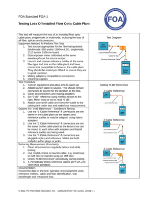
  • 1. © 2012, The Fiber Optic Association, Inc. Cable plant loss FOA-1a.doc, 11/15/14, 1 FOA Standard FOA-1 Testing Loss Of Installed Fiber Optic Cable Plant This test will measure the loss of an installed fiber optic cable plant, singlemode or multimode, including the loss of all fiber, splices and connectors. Equipment Needed To Perform This Test 1. Test source appropriate for the fiber being tested (Multimode: 850 and/or 1300nm LED, singlemode, 1310 and/or 1550 nm laser) 2. Optical power meter calibrated at the same wavelengths as the source output. 3. Launch and receive reference cables of the same fiber type and size as the cable plant and have connectors compatible to those on the cable plant. They should be tested per FOA-2 to ensure they are in good condition. 4. Mating adapters compatible to connectors 5. Cleaning supplies Test Diagram Test Procedure 1. Turn on equipment and allow time to warm-up 2. Attach launch cable to source. This should remain connected to source for the duration of the test. 3. Clean all connectors and mating adapters. 4. Set “0 dB” reference using method shown to the right. Meter may be set to read “0 dB.” 5. Attach source/ref cable and meter/ref cable to the cable plant under test and make loss measurement. Options For “0 dB Reference” - Set Before Testing 1. Use the “1 Cable Reference” if connectors are the same on the cable plant as the testers and reference cables or may be adapted using hybrid adapters. 2. Use the “2 Cable Reference” if connectors are not the same on the cable plant as the testers but can be mated to each other with adapters and hybrid reference cables are being used. 3. Use the “3 Cable Reference” if connectors are plug/jack styles and reference cables are both ended in either plugs or jacks. Reducing Measurement Uncertainty 1. Clean all connectors regularly before and while testing. 2. Use modal control on launch cable, e.g. small loop on SM fiber or mandrel wrap on MM fiber. 3. Check “0 dB Reference” periodically during testing. 4. 4. Periodically check reference cables per FOA-2 to verify their condition. Documentation Record the date of the test, operator, test equipment used, reference method, cable and fiber identification, test wavelength and measured loss. Setting “0 dB” Reference 1 Cable Reference 2 Cable Reference 3 Cable Reference
  • 2. © 2012, The Fiber Optic Association, Inc. Patchcord and Cable loss FOA-2.doc, 11/15/14, 1 FOA Standard FOA-2 Testing Loss Of Fiber Optic Cables, Single-Ended This test will measure the loss of a fiber optic cable, singlemode or multimode, including connectors on each end individually. For short cables, e.g. patchcords, with negligible fiber loss, the measured loss may be considered the loss of the connector mated to the reference connector. Equipment Needed To Perform This Test 1. Test source appropriate for the fiber being tested (Multimode: 850 and/or 1300nm LED, singlemode, 1310 and/or 1550 nm laser) 2. Optical power meter calibrated at the same wavelengths as the source output with adapters to mate to connector type on cable. 3. Launch reference cable that is the same fiber type and size as the cable plant and have connectors compatible to those on the cable. 4. Mating adapters compatible to connectors 5. Cleaning supplies Test Diagram Test Procedure 1. Turn on equipment and allow time to warm-up 2. Attach launch cable to source. This should remain connected to source for the duration of the test. 3. Clean all connectors and mating adapters. 4. Set “0 dB” reference using method shown to the right. Meter may be set to read “0 dB.” 5. Attach source/ref cable and to the cable under test and make loss measurement. 6. Reverse cable and test again. Options For Testing With Different Connector Types 1. If the connector(s) on the cables to test are “plug and jack” type and/or are not compatible to the optical power meter for testing and/or reference, you cannot test single-ended. Use the FOA-1 method with a 2 or 3 Cable Reference as appropriate. Results will include loss of connectors on both ends. Reducing Measurement Uncertainty 1. Clean all connectors regularly before and while testing. 2. Use modal control on launch cable, e.g. small loop on singlemode fiber or mandrel wrap on multimode fiber. 3. Check “0 dB Reference” periodically during testing. Documentation Record the date of the test, operator, test equipment used, reference method, cable and fiber identification, test wavelength and measured loss. Setting “0 dB” Reference
  • 3. © 2012, The Fiber Optic Association, Inc. Measure Optical Power FOA-3.doc, 11/15/14, 1 FOA Standard FOA-3 Measuring Optical Power In Fiber Optic Systems This test will measure the optical power exiting the end of a fiber optic cable. This test is commonly used to measure the coupled power of a fiber optic source in a transmitter, power into a receiver or for setting references for optical loss measurements. Equipment Needed To Perform This Test 1. Fiber optic power meter calibrated at the same wavelength as the source output (e.g. multimode: 850 and/or 1300nm, singlemode, 1310, 1490 and/or 1550 nm, POF 650 nm) capable of measuring optical power in the power range of the source. 2. Optical power meter adapters to mate to connector type on cable. 3. Reference cable that is the same fiber type and size as the cable plant and have connectors compatible to those on the source and cables. 4. Cleaning supplies Test Diagram Test Procedure 1. Turn on meter and allow time to warm-up 2. Set meter to wavelength of source and “dBm” to measure calibrated optical power. 3. Clean all connectors and mating adapters. 4. Attach reference cable to source if testing source power or disconnect cable from receiver. 5. Attach power meter to end of cable and read measured power. Options For Testing Power is generally measured in “dBm” or dB referenced to 1 milliwatt of optical power. Optical power measurements may also be made in Milliwatts (mW) or microwatts (µW) Reducing Measurement Uncertainty 1. Calibrate optical power meter according to manufacturer specified intervals. 2. Clean all connectors and remove meter adapter periodically to clean the adapter and power meter detector. 3. Do not bend fiber optic cables tightly to cause stress loss. Documentation Record the date of the test, operator, test equipment used, cable and fiber identification, test wavelength and measured power. Note: A reference cable or known good patchcord is used for testing source power coupled into a fiber. Receiver power is tested by disconnecting the system cable connecting to the receiver and attaching it to the power meter to measure power.
  • 4. © 2012, The Fiber Optic Association, Inc. Measure Optical Power FOA-3.doc, 11/15/14, 1 FOA Standard FOA-3 Measuring Optical Power In Fiber Optic Systems This test will measure the optical power exiting the end of a fiber optic cable. This test is commonly used to measure the coupled power of a fiber optic source in a transmitter, power into a receiver or for setting references for optical loss measurements. Equipment Needed To Perform This Test 1. Fiber optic power meter calibrated at the same wavelength as the source output (e.g. multimode: 850 and/or 1300nm, singlemode, 1310, 1490 and/or 1550 nm, POF 650 nm) capable of measuring optical power in the power range of the source. 2. Optical power meter adapters to mate to connector type on cable. 3. Reference cable that is the same fiber type and size as the cable plant and have connectors compatible to those on the source and cables. 4. Cleaning supplies Test Diagram Test Procedure 1. Turn on meter and allow time to warm-up 2. Set meter to wavelength of source and “dBm” to measure calibrated optical power. 3. Clean all connectors and mating adapters. 4. Attach reference cable to source if testing source power or disconnect cable from receiver. 5. Attach power meter to end of cable and read measured power. Options For Testing Power is generally measured in “dBm” or dB referenced to 1 milliwatt of optical power. Optical power measurements may also be made in Milliwatts (mW) or microwatts (µW) Reducing Measurement Uncertainty 1. Calibrate optical power meter according to manufacturer specified intervals. 2. Clean all connectors and remove meter adapter periodically to clean the adapter and power meter detector. 3. Do not bend fiber optic cables tightly to cause stress loss. Documentation Record the date of the test, operator, test equipment used, cable and fiber identification, test wavelength and measured power. Note: A reference cable or known good patchcord is used for testing source power coupled into a fiber. Receiver power is tested by disconnecting the system cable connecting to the receiver and attaching it to the power meter to measure power.
  • 5. ©2013, The Fiber Optic Association, Inc. FOA Standard FOA-5 Datalinks.doc 11/15/14 1 FOA Standard FOA-5 Fiber Optic Data Links Definition A fiber optic datalink is a communications subsystem that connects inputs and outputs (I/O) from electronic subsystems and transmits those signals over optical fiber. Fiber optic datalinks may transmit signals that are either analog or digital and of many different, usually standardized, protocols, depending on the communications system(s) it supports. Components A fiber optic datalink consists of fiber optic transceivers or individual transmitters and receivers at either end that transmit over optical fibers. The typical datalink transmits over two fibers for full duplex links, one fiber in each direction. Wavelength division multiplexing may be used to transmit bi- directionally on one fiber. The fibers may be of any type, multimode (graded index or step index) or singlemode. Distance and bandwidth considerations may dictate the choice or grade of the optical fiber or require regeneration. Performance-Power Budget All datalinks are limited by the power budget of the link. The power budget is the difference between the output power of the transmitter and the input power requirements of the receiver. The receiver has an operating range determined by the signal-to-noise ratio (S/N) in the receiver. The S/N ratio is generally quoted for analog links while the bit-error-rate (BER) is used for digital links. BER is basically an inverse function of S/N. Testing Testing the operation of the transceivers with the cable plant includes optical power testing of the output of the transmitter and the receiver input power compared to specifications for the link. FOA Standards for testing cable plant loss and optical power can be used to properly specify test requirements. After the datalink or communications system is installed, testing the BER or SNR may also be done to confirm that the link is operating properly. Documentation Datalinks should be included in all systems documentation, including equipment specifications, transceiver power levels, lengths and routing, test results, etc.
  • 6. ©2013, The Fiber Optic Association, Inc. FOA Standard FOA-5 Datalinks.doc 11/15/14 1 FOA Standard FOA-5 Fiber Optic Data Links Definition A fiber optic datalink is a communications subsystem that connects inputs and outputs (I/O) from electronic subsystems and transmits those signals over optical fiber. Fiber optic datalinks may transmit signals that are either analog or digital and of many different, usually standardized, protocols, depending on the communications system(s) it supports. Components A fiber optic datalink consists of fiber optic transceivers or individual transmitters and receivers at either end that transmit over optical fibers. The typical datalink transmits over two fibers for full duplex links, one fiber in each direction. Wavelength division multiplexing may be used to transmit bi- directionally on one fiber. The fibers may be of any type, multimode (graded index or step index) or singlemode. Distance and bandwidth considerations may dictate the choice or grade of the optical fiber or require regeneration. Performance-Power Budget All datalinks are limited by the power budget of the link. The power budget is the difference between the output power of the transmitter and the input power requirements of the receiver. The receiver has an operating range determined by the signal-to-noise ratio (S/N) in the receiver. The S/N ratio is generally quoted for analog links while the bit-error-rate (BER) is used for digital links. BER is basically an inverse function of S/N. Testing Testing the operation of the transceivers with the cable plant includes optical power testing of the output of the transmitter and the receiver input power compared to specifications for the link. FOA Standards for testing cable plant loss and optical power can be used to properly specify test requirements. After the datalink or communications system is installed, testing the BER or SNR may also be done to confirm that the link is operating properly. Documentation Datalinks should be included in all systems documentation, including equipment specifications, transceiver power levels, lengths and routing, test results, etc.
  • 7. ©2013, The Fiber Optic Association, Inc. FOA Standard FOA-5 Datalinks.doc 11/15/14 1 FOA Standard FOA-5 Fiber Optic Data Links Definition A fiber optic datalink is a communications subsystem that connects inputs and outputs (I/O) from electronic subsystems and transmits those signals over optical fiber. Fiber optic datalinks may transmit signals that are either analog or digital and of many different, usually standardized, protocols, depending on the communications system(s) it supports. Components A fiber optic datalink consists of fiber optic transceivers or individual transmitters and receivers at either end that transmit over optical fibers. The typical datalink transmits over two fibers for full duplex links, one fiber in each direction. Wavelength division multiplexing may be used to transmit bi- directionally on one fiber. The fibers may be of any type, multimode (graded index or step index) or singlemode. Distance and bandwidth considerations may dictate the choice or grade of the optical fiber or require regeneration. Performance-Power Budget All datalinks are limited by the power budget of the link. The power budget is the difference between the output power of the transmitter and the input power requirements of the receiver. The receiver has an operating range determined by the signal-to-noise ratio (S/N) in the receiver. The S/N ratio is generally quoted for analog links while the bit-error-rate (BER) is used for digital links. BER is basically an inverse function of S/N. Testing Testing the operation of the transceivers with the cable plant includes optical power testing of the output of the transmitter and the receiver input power compared to specifications for the link. FOA Standards for testing cable plant loss and optical power can be used to properly specify test requirements. After the datalink or communications system is installed, testing the BER or SNR may also be done to confirm that the link is operating properly. Documentation Datalinks should be included in all systems documentation, including equipment specifications, transceiver power levels, lengths and routing, test results, etc.