SlideShare a Scribd company logo
1 of 14
Download to read offline
How to Use the DTX-EFM2 Fiber Modules to
Test Installed Corning Multimode Pretium
EDGE® Tap
Note these important points regarding measuring loss through an EDGE Tap
Module:
•	 Because the splitters in the tap module have low loss in one direc-
tion and high loss in the other direction, you measure loss through
the module in one direction only (no bi-directional tests).
•	 The splitters in the multimode tap modules are optimized for 	
850 nm VCSEL (Vertical-Cavity Surface-Emitting Lasers), so you test
at only 850 nm.
•	 The network links through the LIVE port on the tap module to the
EDGE module at the far end are duplex, so you test them with the
DTX in Smart Remote mode. The links through the TAP port are all
outputs, so you test them with the DTX in Far End Source mode.
Required Equipment
•	 DTX CableAnalyzer main and remote testers
•	 Two DTX-EFM2 Fiber Modules
•	 Two SC/LC EF-TRC test reference cords
•	 Two LC/LC 50 μm multimode test reference cords
•	 One duplex LC/LC adapter or two simplex LC/LC adapters
•	 One MTP/LC 12-fiber fan-out cable with Corning Universal polarity
•	 Fiber inspection microscope (such as the FT500 FiberInspector
Microscope) with LC adapter
•	 Fiber cleaning supplies for LC and MTP connectors
The Corning Pretium EDGE® Tap
Module allows passive tapping
into optical networks for mon-
itoring purposes. The modules
contain splitters that divide
each optical signal into two
outputs, one for network link
traffic and one for monitoring.
To ensure that the installed
module operates correctly and
to meet the requirements for
Corning warranty coverage, you
must measure the loss of the
network links with the module
installed. Optionally, you can
also measure the loss of the
tap links from the module to
ensure that the links to your
monitoring equipment operate
correctly.
Calculating the Loss Budgets
To have a test limit that accounts for the losses of the splitters and MTP connectors, you calculate loss budgets for
each of the three paths you will test. Then you make a custom test limit that uses your loss budget values. The cus-
tom limit is based on the 1000BASE-SX limit, which specifies tests at only 850 nm.
You calculate loss budgets for these three paths of each link, which are shown in Figure 1:
•	 The network link. Note that if the network links are different lengths, you will need to calculate a budget for
each link.
•	 The tap port link from the near end (optional).
•	 The tap port link from the far end (optional). Note that if the network links are different lengths, you will
need to calculate a budget for each link.
B
6
1211
AB
5
109
AB
4
87
AB
3
6
PortTapModule
PartNumber
Serial
MADEINMEXICO
TAPLIVE
5
AB
2
43
AB
1
21
A
WARRANTY
VOID
Link under test
Pretium EDGE Tap
Module
Pretium EDGE
Module
B
6
1211
AB
5
109
AB
4
87
AB
3
6
PnPModule
PartNumber
Serial
MADEINMEXICO
5
AB
2
43
AB
1
21
A
WARRANTY
VOID
Do not
disconnect
the output port
2
4
AB
3
B
1
21
A
B
2
3
B
1
21
A
Do not
disconnect
the output port
TRC
TRC
Near End Far End
DTX in Smart
Remote mode
EF-TRC 2 EF-TRC 1
B
6
1211
AB
5
109
AB
4
87
AB
3
6
PortTapModule
PartNumber
Serial
MADEINMEXICO
TAPLIVE
5
AB
2
43
AB
1
21
A
WARRANTY
VOID
Tap port fan-out cable
(Corning Universal polarity)
Pretium EDGE Tap
Module
Pretium EDGE
Module
B
6
1211
AB
5
109
AB
4
87
AB
3
6
PnPModule
PartNumber
Serial
MADEINMEXICO
5
AB
2
43
AB
1
21
A
WARRANTY
VOID
11
1
Connect to
even-numbered
connectors
Connect to
odd-numbered
connectors
9
7
5
3
2
4
6
8
10
12
Near End Far End
DTX in
Far End Source
mode
Do not
disconnect
the output port
Smart remote with
OUTPUT port transmitting
at 850 nm (LED is solid red)
EF-TRC
B
6
1211
AB
5
109
AB
4
87
AB
3
6
PortTapModule
PartNumber
Serial
MADEINMEXICO
TAPLIVE
5
AB
2
43
AB
1
21
A
WARRANTY
VOID
Link under test
Pretium EDGE Tap
Module
Pretium EDGE
Module
B
6
1211
AB
5
109
AB
4
87
AB
3
6
PnPModule
PartNumber
Serial
MADEINMEXICO
5
AB
2
43
AB
1
21
A
WARRANTY
VOID
Do not
disconnect
the output port12
2
Connect to
even-numbered
connectors
Connect to
even-numbered
connectors
10
8
6
4
12
10
8
6
4
2
Near End Far End
Tap port fan-out cable
(Corning Universal polarity)
DTX in
Far End Source
mode
Smart remote with
OUTPUT port transmitting
at 850 nm (LED is solid red)
EF-TRC
Component Maximum loss (dB)*
OM4 EDGE trunk fiber 2.8 dB/km (0.00085 dB/ft)
MTP® mated pair loss 0.35
LC mated pair loss 0.15
50/50 splitter inside the EDGE Tap Module 3.8
30/70 splitter inside the EDGE Tap Module 6.6/1.8
*Insertion loss when mated to other system components with similar performance specifications.
Table 1 shows the values to use for your loss budget calculations.
Figure 2 shows an example of a loss budget calculation for a test from the far end through the tap port and through
a fan-out cable. Note that the loss of the LC connection at the end of the fan-out cable is not included in this ex-
ample.
The calculation includes the loss of a 600 m trunk fiber and a 10 m tap port fan-out cable:
•	 Loss for 600 m of OM4 EDGE trunk fiber for a network link: 2.8 dB/km x .6 km = 1.68 dB
•	 Loss for 10 m of OM4 EDGE trunk fiber for a tap port harness: 2.8 dB/km x .01 km = 0.028 dBB
6
1211
AB
5
109
AB
4
87
AB
3
6
PortTapModule
PartNumber
Serial
MADEINMEXICO
TAPLIVE
5
AB
2
43
AB
1
21
A
WARRANTY
VOID
Tap port fan-out cable
(Corning Universal polarity)
Pretium EDGE Tap
Module
Pretium EDGE
Module
B
6
1211
AB
5
109
AB
4
87
AB
3
6
PnPModule
PartNumber
Serial
MADEINMEXICO
5
AB
2
43
AB
1
21
A
WARRANTY
VOID
11
1
Connect to
even-numbered
connectors
Connect to
odd-numbered
connectors
9
7
5
3
2
4
6
8
10
12
Near End Far End
DTX in
Far End Source
mode
Do not
disconnect
the output port
Smart remote with
OUTPUT port transmitting
at 850 nm (LED is solid red)
EF-TRC
Figure 2. Example of a Loss Budget Calculation for Testing Network Links
For more examples of loss budget calculations, see the Corning Standard Recommended Procedure (SRP) document
number 003-126 on the Corning web site.
Setting Up a Custom Test Limit
Next, make a custom test limit that will include your loss budget values. The first loss budget value you enter will be
for the first network link you will test.
1.	 Turn the rotary switch to SETUP.
2.	 Select Fiber Loss.
3.	 On the Fiber Loss screen, set the Remote End Setup to Smart Remote and set Bi-Directional to No.
4.	 Select Test Limit.
5.	 On the Test Limit screen, press F1 More, then select Custom.
6.	 Press F1 Create.
7.	 Select Name, enter a name for your limit, then press SAVE.
8.	 Select Use Default Values From.
9.	 On the Use Default Values From screen, select Application, then select 1000BASE-SX.
10.	On the Custom screen, select Maximum Length.
11.	Set the maximum length to a value that is longer than the longest trunk in the fiber network, then press
SAVE.
12.	On the Custom screen, select Maximum Loss at 850 nm.
13.	Set the Maximum Loss at 850 nm to the calculated budget for the first network link you will test, then press
SAVE. Note that if the network links are different lengths, you will need to change this value accordingly
before you test each link.
14.	On the Custom screen, press SAVE to save the custom limit.
15.	Highlight your new custom limit, then press ENTER to select it.
On the settings tabs of the Fiber Loss screen, select these settings:
•	 Fiber Type: OM4 Multimode 50
•	 Number of Adapters/Number of Splices: Not used, since you will calculate the loss budget manually
•	 Connector Type: LC
•	 Test Method: 1 Jumper
Testing the Network Links
The network links are duplex connections, so you can use Smart Remote mode to test both fibers in each link.
Set the Reference for Smart Remote Mode
1.	 Turn on the main and remote DTX testers and let them sit for 5 minutes. Allow additional time if the modules
have been stored above or below ambient temperature.
2.	 Turn the rotary switch to SETUP, then select Fiber Loss.
3.	 Select Remote End Setup, then select Smart Remote.
4.	 Turn the rotary switch to SPECIAL FUNCTIONS, then select Set Reference. If both a fiber module and a twist-
ed pair or coaxial adapter are attached, select Fiber Module next.
5.	 Clean and inspect the connectors on the tester, remote, and test reference cords. Connect the tester and
remote as shown in Figure 3 for setting the reference.
6.	 Press TEST
7.	 The View Reference screen shows the reference values and the date and time the reference was set. For
50/125 μm, the reference values should be better than -24.50 dBm where -23.50 dBm is better than 	
-24.50 dBm. If the values are good, press F2 OK. If not, clean all fiber connections and set the reference
again.
8.	 Press F2 OK.
Figure 3. Reference and TRC Test Connections for Smart Remote Mode
EF-TRC 1
EF-TRC 2
EF-TRC 1
EF-TRC 2
TRC test
connections
Reference
connections
Additional
TRC
Additional
TRC
Next, verify that the test reference cords (TRCs) you will add are good:
1.	 Disconnect the test reference cords from the INPUT ports on the tester and smart remote.
2.	 Make the connections shown in Figure 3 for testing the TRCs.
3.	 Turn the rotary switch to AUTOTEST, then press TEST.
4.	 Press ENTER to see the test results. The loss for each fiber (Input Fiber and Output Fiber) in both directions
must be no more than 0.15 dB at 850 nm. If the loss is too high, clean the connections you made for the
TRC test and do the test again. Remember not to disconnect the fibers from the DTX output ports. If you do,
you must set the reference again.
5.	 Save the test results to show that you used good test reference cords to test the fiber links.
B
6
1211
AB
5
109
AB
4
87
AB
3
6
PortTapModule
PartNumber
Serial
MADEINMEXICO
TAPLIVE
5
AB
2
43
AB
1
21
A
WARRANTY
VOID
Link under test
Pretium EDGE Tap
Module
Pretium EDGE
Module
B
6
1211
AB
5
109
AB
4
87
AB
3
6
PnPModule
PartNumber
Serial
MADEINMEXICO
5
AB
2
43
AB
1
21
A
WARRANTY
VOID
Do not
disconnect
the output port
2
4
AB
3
B
1
21
A
B
2
3
B
1
21
A
Do not
disconnect
the output port
TRC
TRC
Near End Far End
DTX in Smart
Remote mode
EF-TRC 2 EF-TRC 1
Testing the Tap Port Links
It’s not necessary to test the tap port links to meet Corning’s requirements for warranty coverage, but you may want
to do so to make sure your tap port links are good.
Note that this article shows the TAP port connected to a Corning Universal polarity fan-out cable. You can also con-
nect the TAP port to another Pretium EDGE module. In that case, you would add another MTP and LC mated pair loss
to your loss budget, and you would connect the DTX tester to the LC ports in the module.
TAP Port Connections
When you connect the remote to the EDGE Tap module at the near end, you measure the tap port link’s loss at the
odd numbered connectors on the tap port fan-out cable or EDGE module connected to the tap port. When you con-
nect the remote to the EDGE module at the far end, you measure the tap port link’s loss at the even-numbered con-
nectors on the tap port fan-out cable or EDGE module connected to the tap port. Figure 5 shows these connections.
Figure 5. Connections from the Near and Far End Modules to the TAP Port Cable
Set the Reference for Far End Source Mode
Because all of the tap port connections are outputs, you will use Far End Source mode to test all the tap port links
in the same direction, one at a time. Set the reference and test your test reference cords (TRCs) as follows:
1.	 Turn on the main and remote DTX testers and let them sit for 5 minutes. Allow additional time if the modules
have been stored above or below ambient temperature.
2.	 Turn the rotary switch to SETUP, then select Fiber Loss.
3.	 Select Remote End Setup, then select Far End Source.
4.	 Clean and inspect the connectors on the tester, smart remote, and test reference cords. Connect the tester
and smart remote as shown in Figure 6 for setting the reference.
5.	 On the smart remote, hold down the button next to the VFL port for approximately 3 seconds to turn on the
OUTPUT port at 850 nm. The LED is red for 850 nm and green for 1300 nm.
6.	 Turn the rotary switch to SPECIAL FUNCTIONS, then select Set Reference. If both a fiber module and a twist-
ed pair or coaxial adapter are attached, select Fiber Module next.
7.	 Press TEST.
8.	 The View Reference screen shows the reference value and the date and time the reference was set. For
50/125 μm, the reference value should be better than -24.50 dBm where -23.50 dBm is better than 	
-24.50 dBm. If the value is good, press F2 OK. If not, clean all fiber connections and set the reference again.
9.	 Press F2 OK.
Figure 6. Reference and TRC Test Connections for Far End Source Mode
Next, verify that the test reference cord (TRC) you will add is good:
1.	 Disconnect the test reference cords from the INPUT port on the tester.
2.	 Make the connections shown in Figure 6 for testing the TRC.
3.	 Turn the rotary switch to AUTOTEST, then press TEST.
4.	 Press ENTER to see the test results. The loss must be no more than 0.15 dB at 850 nm. If the loss is too
high, clean the connections you made for the TRC test and do the test again. Remember not to disconnect
the fiber from the remote’s output port. If you do, you must also set the reference again.
5.	 Save the test results to show that you used a good test reference cord to test the fiber links.
Test the Tap Port Links from the Near End
1.	 Change the value for the Maximum Loss at 850 nm in your custom limit to the applicable loss budget value
for the fiber path from the near end through the tap port.
2.	 Clean and inspect the even-numbered LC connectors on the EDGE Tap module (near end) and the odd-num-
bered connectors on the tap port fan-out cable or third EDGE module.
3.	 Make the connections shown in Figure 7 if you will do the test through a fan-out cable, or in Figure 8 if you
will do the test through a third EDGE module.
4.	 Make sure the smart remote’s OUTPUT port is still transmitting at 850 nm (LED is solid red).
5.	 Turn the rotary switch to AUTOTEST, then press ENTER.
6.	 If the test passes, save the results. If it fails, clean and inspect the connections again, or troubleshoot as
necessary, then test again.
7.	 Repeat steps 3-6 for all tap port links.
B
6
1211
AB
5
109
AB
4
87
AB
3
6
PortTapModule
PartNumber
Serial
MADEINMEXICO
TAPLIVE
5
AB
2
43
AB
1
21
A
WARRANTY
VOID
Tap port fan-out cable
(Corning Universal polarity)
Pretium EDGE Tap
Module
Pretium EDGE
Module
B
6
1211
AB
5
109
AB
4
87
AB
3
6
PnPModule
PartNumber
Serial
MADEINMEXICO
5
AB
2
43
AB
1
21
A
WARRANTY
VOID
11
1
Connect to
even-numbered
connectors
Connect to
odd-numbered
connectors
9
7
5
3
2
4
6
8
10
12
Near End Far End
DTX in
Far End Source
mode
Do not
disconnect
the output port
Smart remote with
OUTPUT port transmitting
at 850 nm (LED is solid red)
EF-TRC
Figure 7. Connections for Testing the Tap Port Links from the Near End through a Fan-Out Cable
EF-TRC
B
6
1211
AB
5
109
AB
4
87
AB
3
6
PortTapModule
PartNumber
Serial
MADEINMEXICO
TAPLIVE
5
AB
2
43
AB
1
21
A
WARRANTY
VOID
Link under test
Pretium EDGE Tap
Module
Pretium EDGE
Module
B
6
1211
AB
5
109
AB
4
87
AB
3
6
PnPModule
PartNumber
Serial
MADEINMEXICO
5
AB
2
43
AB
1
21
A
WARRANTY
VOID
Do not
disconnect
the output port
Connect to
even-numbered
connectors
12
10
8
6
4
2
Near End Far End
12
2
108
64
B
6
12
11 A
B
5
10
9 A
B
4
8
7 A
B
3
6
PnP
M
od
ule
Par
t Num
be
r
Ser
ial
MA
DE
IN
ME
XI
CO
5 A
B
2
4
3 A
B
1
2
1 A
WAR
RANTY
VOID
Connect to
even-numbered
connectors
DTX in
Far End Source
mode
Pretium EDGE
Module
TRC
Smart remote with
OUTPUT port transmitting
at 850 nm (LED is solid red)
Figure 8. Connections for Testing the Tap Port Links from the Near End through an EDGE Module
Test the Tap Port Links from the Far End
1.	 Change the value for the Maximum Loss at 850 nm in your custom limit to the applicable loss budget value
for the first tap port link you will test from the far end through the tap port.
2.	 Clean and inspect the even-numbered LC connectors on the EDGE module (far end) and the even-numbered-
connectors on the tap port fan-out cable or third EDGE module.
3.	 Make the connections shown in Figure 9 if you will do the test through a fan-out cable, or in Figure 10 if you
will do the test through a third EDGE module.
4.	 Make sure the smart remote’s OUTPUT port is still transmitting at 850 nm (LED is solid red).
5.	 Turn the rotary switch to AUTOTEST, then press ENTER.
6.	 If the test passes, save the results. If it fails, clean and inspect the connections again, or troubleshoot as
necessary,then test again.
7.	 If the network links are different lengths, change the value for the Maximum Loss at 850 nm in your custom
limit to the applicable loss budget value for the next tap port link.
8.	 Repeat steps 3-7 for all the tap port links.
B
6
1211
AB
5
109
AB
4
87
AB
3
6
PortTapModule
PartNumber
Serial
MADEINMEXICO
TAPLIVE
5
AB
2
43
AB
1
21
A
WARRANTY
VOID
Link under test
Pretium EDGE Tap
Module
Pretium EDGE
Module
B
6
1211
AB
5
109
AB
4
87
AB
3
6
PnPModule
PartNumber
Serial
MADEINMEXICO
5
AB
2
43
AB
1
21
A
WARRANTY
VOID
Do not
disconnect
the output port12
2
Connect to
even-numbered
connectors
Connect to
even-numbered
connectors
10
8
6
4
12
10
8
6
4
2
Near End Far End
Tap port fan-out cable
(Corning Universal polarity)
DTX in
Far End Source
mode
Smart remote with
OUTPUT port transmitting
at 850 nm (LED is solid red)
EF-TRC
Figure 9. Connections for Testing the Tap Port Links from the Far End through a Fan-Out Cable
EF-TRC
B
6
1211
AB
5
109
AB
4
87
AB
3
6
PortTapModule
PartNumber
Serial
MADEINMEXICO
TAPLIVE
5
AB
2
43
AB
1
21
A
WARRANTY
VOID
Link under test
Pretium EDGE Tap
Module
Pretium EDGE
Module
B
6
1211
AB
5
109
AB
4
87
AB
3
6
PnPModule
PartNumber
Serial
MADEINMEXICO
5
AB
2
43
AB
1
21
A
WARRANTY
VOID
Do not
disconnect
the output port
Connect to
even-numbered
connectors
12
10
8
6
4
2
Near End Far End
12
2
108
64
B
6
12
11 A
B
5
10
9 A
B
4
8
7 A
B
3
6
PnP
M
od
ule
Par
t Num
be
r
Ser
ial
MA
DE
IN
ME
XI
CO
5 A
B
2
4
3 A
B
1
2
1 A
WAR
RANTY
VOID
Connect to
even-numbered
connectors
DTX in
Far End Source
mode
Pretium EDGE
Module
TRC
Smart remote with
OUTPUT port transmitting
at 850 nm (LED is solid red)
Figure 10. Connections for Testing the Tap Port Links from the Far End through an EDGE Module

More Related Content

What's hot

Xpic implementation xpd alignment interference test
Xpic implementation xpd alignment interference testXpic implementation xpd alignment interference test
Xpic implementation xpd alignment interference testKhalil Al-Alami
 
2 Basic Principal Of Utp Installation
2 Basic Principal Of Utp Installation2 Basic Principal Of Utp Installation
2 Basic Principal Of Utp InstallationMrirfan
 
Tranzeo TR-5a Series (quantumwimax.com)
Tranzeo TR-5a Series (quantumwimax.com)Tranzeo TR-5a Series (quantumwimax.com)
Tranzeo TR-5a Series (quantumwimax.com)Ari Zoldan
 
3 Basic Principal Of Fo Installation
3 Basic Principal Of Fo Installation3 Basic Principal Of Fo Installation
3 Basic Principal Of Fo InstallationMrirfan
 
5 Installing Premises Cabling System
5 Installing Premises Cabling System5 Installing Premises Cabling System
5 Installing Premises Cabling SystemMrirfan
 
Ap Caanopy User Guide
Ap Caanopy User GuideAp Caanopy User Guide
Ap Caanopy User GuideNanda Mambo
 
Fiber Optic Spitter for PON network
Fiber Optic Spitter for PON networkFiber Optic Spitter for PON network
Fiber Optic Spitter for PON networkSteven Zhang
 
Performance Comparison of Uncoded OFDM & Uncoded Adaptive OFDM System Over AW...
Performance Comparison of Uncoded OFDM & Uncoded Adaptive OFDM System Over AW...Performance Comparison of Uncoded OFDM & Uncoded Adaptive OFDM System Over AW...
Performance Comparison of Uncoded OFDM & Uncoded Adaptive OFDM System Over AW...IOSR Journals
 
10Gb/s DWDM XFP Transceiver Hot Pluggable, Duplex LC, +3.3V & +5V, 100GHz ITU...
10Gb/s DWDM XFP Transceiver Hot Pluggable, Duplex LC, +3.3V & +5V, 100GHz ITU...10Gb/s DWDM XFP Transceiver Hot Pluggable, Duplex LC, +3.3V & +5V, 100GHz ITU...
10Gb/s DWDM XFP Transceiver Hot Pluggable, Duplex LC, +3.3V & +5V, 100GHz ITU...Allen He
 
Gsm 2 g rollout dt
Gsm 2 g rollout dtGsm 2 g rollout dt
Gsm 2 g rollout dtINAYAT ULHAQ
 
Tranzeo TR – 5plus Series (quantumwimax.com)
Tranzeo TR – 5plus Series (quantumwimax.com)Tranzeo TR – 5plus Series (quantumwimax.com)
Tranzeo TR – 5plus Series (quantumwimax.com)Ari Zoldan
 
Mitsubishi ac servos melservo j3-dienhathe.vn
Mitsubishi ac servos melservo j3-dienhathe.vnMitsubishi ac servos melservo j3-dienhathe.vn
Mitsubishi ac servos melservo j3-dienhathe.vnDien Ha The
 
Mtr 2000 800_900_catsheet
Mtr 2000 800_900_catsheetMtr 2000 800_900_catsheet
Mtr 2000 800_900_catsheetmontaluisam
 
Opti x rtn 910950980 hardware description wind
Opti x rtn 910950980 hardware description windOpti x rtn 910950980 hardware description wind
Opti x rtn 910950980 hardware description windnctgayaranga
 
Kyl 500 s data transceiver
Kyl 500 s data transceiverKyl 500 s data transceiver
Kyl 500 s data transceiverSunny Zhou
 
Annex 4 part 1-fdh (i) installation guide
Annex 4 part 1-fdh (i) installation guideAnnex 4 part 1-fdh (i) installation guide
Annex 4 part 1-fdh (i) installation guideIgors Cardoso
 

What's hot (20)

Xpic implementation xpd alignment interference test
Xpic implementation xpd alignment interference testXpic implementation xpd alignment interference test
Xpic implementation xpd alignment interference test
 
Sfp+ tunable
Sfp+ tunableSfp+ tunable
Sfp+ tunable
 
2 Basic Principal Of Utp Installation
2 Basic Principal Of Utp Installation2 Basic Principal Of Utp Installation
2 Basic Principal Of Utp Installation
 
Tranzeo TR-5a Series (quantumwimax.com)
Tranzeo TR-5a Series (quantumwimax.com)Tranzeo TR-5a Series (quantumwimax.com)
Tranzeo TR-5a Series (quantumwimax.com)
 
3 Basic Principal Of Fo Installation
3 Basic Principal Of Fo Installation3 Basic Principal Of Fo Installation
3 Basic Principal Of Fo Installation
 
5 Installing Premises Cabling System
5 Installing Premises Cabling System5 Installing Premises Cabling System
5 Installing Premises Cabling System
 
ENGR M FAHIM IQBAL CV
ENGR M FAHIM IQBAL CVENGR M FAHIM IQBAL CV
ENGR M FAHIM IQBAL CV
 
Paso neo a
Paso neo aPaso neo a
Paso neo a
 
Ap Caanopy User Guide
Ap Caanopy User GuideAp Caanopy User Guide
Ap Caanopy User Guide
 
Tr5 Amp
Tr5 AmpTr5 Amp
Tr5 Amp
 
Fiber Optic Spitter for PON network
Fiber Optic Spitter for PON networkFiber Optic Spitter for PON network
Fiber Optic Spitter for PON network
 
Performance Comparison of Uncoded OFDM & Uncoded Adaptive OFDM System Over AW...
Performance Comparison of Uncoded OFDM & Uncoded Adaptive OFDM System Over AW...Performance Comparison of Uncoded OFDM & Uncoded Adaptive OFDM System Over AW...
Performance Comparison of Uncoded OFDM & Uncoded Adaptive OFDM System Over AW...
 
10Gb/s DWDM XFP Transceiver Hot Pluggable, Duplex LC, +3.3V & +5V, 100GHz ITU...
10Gb/s DWDM XFP Transceiver Hot Pluggable, Duplex LC, +3.3V & +5V, 100GHz ITU...10Gb/s DWDM XFP Transceiver Hot Pluggable, Duplex LC, +3.3V & +5V, 100GHz ITU...
10Gb/s DWDM XFP Transceiver Hot Pluggable, Duplex LC, +3.3V & +5V, 100GHz ITU...
 
Gsm 2 g rollout dt
Gsm 2 g rollout dtGsm 2 g rollout dt
Gsm 2 g rollout dt
 
Tranzeo TR – 5plus Series (quantumwimax.com)
Tranzeo TR – 5plus Series (quantumwimax.com)Tranzeo TR – 5plus Series (quantumwimax.com)
Tranzeo TR – 5plus Series (quantumwimax.com)
 
Mitsubishi ac servos melservo j3-dienhathe.vn
Mitsubishi ac servos melservo j3-dienhathe.vnMitsubishi ac servos melservo j3-dienhathe.vn
Mitsubishi ac servos melservo j3-dienhathe.vn
 
Mtr 2000 800_900_catsheet
Mtr 2000 800_900_catsheetMtr 2000 800_900_catsheet
Mtr 2000 800_900_catsheet
 
Opti x rtn 910950980 hardware description wind
Opti x rtn 910950980 hardware description windOpti x rtn 910950980 hardware description wind
Opti x rtn 910950980 hardware description wind
 
Kyl 500 s data transceiver
Kyl 500 s data transceiverKyl 500 s data transceiver
Kyl 500 s data transceiver
 
Annex 4 part 1-fdh (i) installation guide
Annex 4 part 1-fdh (i) installation guideAnnex 4 part 1-fdh (i) installation guide
Annex 4 part 1-fdh (i) installation guide
 

Similar to How to Use the DTX-EFM2 Fiber Modules to Test Installed Corning Multimode Pretium EDGE® Tap

Iai ethernet ip_pcon_acon_specsheet
Iai ethernet ip_pcon_acon_specsheetIai ethernet ip_pcon_acon_specsheet
Iai ethernet ip_pcon_acon_specsheetElectromate
 
Nd at s best practices for single mode tier i ii testing 01-2011
Nd at s   best practices for single mode tier i  ii testing 01-2011Nd at s   best practices for single mode tier i  ii testing 01-2011
Nd at s best practices for single mode tier i ii testing 01-2011Dean Murray
 
V350-35-RA22_INSTAL-GUIDE_10-08
V350-35-RA22_INSTAL-GUIDE_10-08V350-35-RA22_INSTAL-GUIDE_10-08
V350-35-RA22_INSTAL-GUIDE_10-08Cara Bereck Levy
 
BlueOptics Bo65j27610d 10gbase-bx-u xfp transceiver tx1270nm-rx1330nm 10 km s...
BlueOptics Bo65j27610d 10gbase-bx-u xfp transceiver tx1270nm-rx1330nm 10 km s...BlueOptics Bo65j27610d 10gbase-bx-u xfp transceiver tx1270nm-rx1330nm 10 km s...
BlueOptics Bo65j27610d 10gbase-bx-u xfp transceiver tx1270nm-rx1330nm 10 km s...CBO GmbH
 
BlueOptics Bo31j856s3d 10gbase-sr xfp transceiver 850nm 300m multimode lc dup...
BlueOptics Bo31j856s3d 10gbase-sr xfp transceiver 850nm 300m multimode lc dup...BlueOptics Bo31j856s3d 10gbase-sr xfp transceiver 850nm 300m multimode lc dup...
BlueOptics Bo31j856s3d 10gbase-sr xfp transceiver 850nm 300m multimode lc dup...CBO GmbH
 
3 g rf_optimisation_basics
3 g rf_optimisation_basics3 g rf_optimisation_basics
3 g rf_optimisation_basicsMd.Akm Sahansha
 
BlueOptics Bo65j33610d 10gbase-bx-d xfp transceiver tx1330nm-rx1270nm 10 km s...
BlueOptics Bo65j33610d 10gbase-bx-d xfp transceiver tx1330nm-rx1270nm 10 km s...BlueOptics Bo65j33610d 10gbase-bx-d xfp transceiver tx1330nm-rx1270nm 10 km s...
BlueOptics Bo65j33610d 10gbase-bx-d xfp transceiver tx1330nm-rx1270nm 10 km s...CBO GmbH
 
BlueOptics Bo31j136s4d 10gbase-lrm xfp transceiver 1310nm 220m multimode lc d...
BlueOptics Bo31j136s4d 10gbase-lrm xfp transceiver 1310nm 220m multimode lc d...BlueOptics Bo31j136s4d 10gbase-lrm xfp transceiver 1310nm 220m multimode lc d...
BlueOptics Bo31j136s4d 10gbase-lrm xfp transceiver 1310nm 220m multimode lc d...CBO GmbH
 
BlueOptics Bo65 j33640d 10gbase-bx-d xfp transceiver tx1330nm-rx1270nm 40 km ...
BlueOptics Bo65 j33640d 10gbase-bx-d xfp transceiver tx1330nm-rx1270nm 40 km ...BlueOptics Bo65 j33640d 10gbase-bx-d xfp transceiver tx1330nm-rx1270nm 40 km ...
BlueOptics Bo65 j33640d 10gbase-bx-d xfp transceiver tx1330nm-rx1270nm 40 km ...CBO GmbH
 
BlueOptics Bo31h13610d 2-4-8gbase-lw xfp transceiver 1310nm 10km singlemode l...
BlueOptics Bo31h13610d 2-4-8gbase-lw xfp transceiver 1310nm 10km singlemode l...BlueOptics Bo31h13610d 2-4-8gbase-lw xfp transceiver 1310nm 10km singlemode l...
BlueOptics Bo31h13610d 2-4-8gbase-lw xfp transceiver 1310nm 10km singlemode l...CBO GmbH
 
BlueOptics Bo65j33660d 10gbase-bx-d xfp transceiver tx1330nm-rx1270nm 60 km s...
BlueOptics Bo65j33660d 10gbase-bx-d xfp transceiver tx1330nm-rx1270nm 60 km s...BlueOptics Bo65j33660d 10gbase-bx-d xfp transceiver tx1330nm-rx1270nm 60 km s...
BlueOptics Bo65j33660d 10gbase-bx-d xfp transceiver tx1330nm-rx1270nm 60 km s...CBO GmbH
 
BlueOptics Bo31j15680d 10gbase-zr xfp transceiver 1550nm 80km singlemode lc d...
BlueOptics Bo31j15680d 10gbase-zr xfp transceiver 1550nm 80km singlemode lc d...BlueOptics Bo31j15680d 10gbase-zr xfp transceiver 1550nm 80km singlemode lc d...
BlueOptics Bo31j15680d 10gbase-zr xfp transceiver 1550nm 80km singlemode lc d...CBO GmbH
 
BlueOptics Bo66hxx680d 2-4-8gbase-cwdm xfp transceiver 1471nm - 1611nm 80km s...
BlueOptics Bo66hxx680d 2-4-8gbase-cwdm xfp transceiver 1471nm - 1611nm 80km s...BlueOptics Bo66hxx680d 2-4-8gbase-cwdm xfp transceiver 1471nm - 1611nm 80km s...
BlueOptics Bo66hxx680d 2-4-8gbase-cwdm xfp transceiver 1471nm - 1611nm 80km s...CBO GmbH
 

Similar to How to Use the DTX-EFM2 Fiber Modules to Test Installed Corning Multimode Pretium EDGE® Tap (20)

Iai ethernet ip_pcon_acon_specsheet
Iai ethernet ip_pcon_acon_specsheetIai ethernet ip_pcon_acon_specsheet
Iai ethernet ip_pcon_acon_specsheet
 
Nd at s best practices for single mode tier i ii testing 01-2011
Nd at s   best practices for single mode tier i  ii testing 01-2011Nd at s   best practices for single mode tier i  ii testing 01-2011
Nd at s best practices for single mode tier i ii testing 01-2011
 
CATV Optical Transmitter
CATV Optical TransmitterCATV Optical Transmitter
CATV Optical Transmitter
 
V350-35-RA22_INSTAL-GUIDE_10-08
V350-35-RA22_INSTAL-GUIDE_10-08V350-35-RA22_INSTAL-GUIDE_10-08
V350-35-RA22_INSTAL-GUIDE_10-08
 
PON design considerations for FTTH FTTx
PON design considerations for FTTH FTTxPON design considerations for FTTH FTTx
PON design considerations for FTTH FTTx
 
Drive Training - Copy.pptx
Drive Training - Copy.pptxDrive Training - Copy.pptx
Drive Training - Copy.pptx
 
BlueOptics Bo65j27610d 10gbase-bx-u xfp transceiver tx1270nm-rx1330nm 10 km s...
BlueOptics Bo65j27610d 10gbase-bx-u xfp transceiver tx1270nm-rx1330nm 10 km s...BlueOptics Bo65j27610d 10gbase-bx-u xfp transceiver tx1270nm-rx1330nm 10 km s...
BlueOptics Bo65j27610d 10gbase-bx-u xfp transceiver tx1270nm-rx1330nm 10 km s...
 
BlueOptics Bo31j856s3d 10gbase-sr xfp transceiver 850nm 300m multimode lc dup...
BlueOptics Bo31j856s3d 10gbase-sr xfp transceiver 850nm 300m multimode lc dup...BlueOptics Bo31j856s3d 10gbase-sr xfp transceiver 850nm 300m multimode lc dup...
BlueOptics Bo31j856s3d 10gbase-sr xfp transceiver 850nm 300m multimode lc dup...
 
3 g rf_optimisation_basics
3 g rf_optimisation_basics3 g rf_optimisation_basics
3 g rf_optimisation_basics
 
BlueOptics Bo65j33610d 10gbase-bx-d xfp transceiver tx1330nm-rx1270nm 10 km s...
BlueOptics Bo65j33610d 10gbase-bx-d xfp transceiver tx1330nm-rx1270nm 10 km s...BlueOptics Bo65j33610d 10gbase-bx-d xfp transceiver tx1330nm-rx1270nm 10 km s...
BlueOptics Bo65j33610d 10gbase-bx-d xfp transceiver tx1330nm-rx1270nm 10 km s...
 
BlueOptics Bo31j136s4d 10gbase-lrm xfp transceiver 1310nm 220m multimode lc d...
BlueOptics Bo31j136s4d 10gbase-lrm xfp transceiver 1310nm 220m multimode lc d...BlueOptics Bo31j136s4d 10gbase-lrm xfp transceiver 1310nm 220m multimode lc d...
BlueOptics Bo31j136s4d 10gbase-lrm xfp transceiver 1310nm 220m multimode lc d...
 
E2020 TDR CATV Training
E2020 TDR CATV TrainingE2020 TDR CATV Training
E2020 TDR CATV Training
 
BlueOptics Bo65 j33640d 10gbase-bx-d xfp transceiver tx1330nm-rx1270nm 40 km ...
BlueOptics Bo65 j33640d 10gbase-bx-d xfp transceiver tx1330nm-rx1270nm 40 km ...BlueOptics Bo65 j33640d 10gbase-bx-d xfp transceiver tx1330nm-rx1270nm 40 km ...
BlueOptics Bo65 j33640d 10gbase-bx-d xfp transceiver tx1330nm-rx1270nm 40 km ...
 
BlueOptics Bo31h13610d 2-4-8gbase-lw xfp transceiver 1310nm 10km singlemode l...
BlueOptics Bo31h13610d 2-4-8gbase-lw xfp transceiver 1310nm 10km singlemode l...BlueOptics Bo31h13610d 2-4-8gbase-lw xfp transceiver 1310nm 10km singlemode l...
BlueOptics Bo31h13610d 2-4-8gbase-lw xfp transceiver 1310nm 10km singlemode l...
 
Commisioning.pptx
Commisioning.pptxCommisioning.pptx
Commisioning.pptx
 
BlueOptics Bo65j33660d 10gbase-bx-d xfp transceiver tx1330nm-rx1270nm 60 km s...
BlueOptics Bo65j33660d 10gbase-bx-d xfp transceiver tx1330nm-rx1270nm 60 km s...BlueOptics Bo65j33660d 10gbase-bx-d xfp transceiver tx1330nm-rx1270nm 60 km s...
BlueOptics Bo65j33660d 10gbase-bx-d xfp transceiver tx1330nm-rx1270nm 60 km s...
 
E2020 TDR Telco Training
E2020 TDR Telco TrainingE2020 TDR Telco Training
E2020 TDR Telco Training
 
PON testing.pdf
PON testing.pdfPON testing.pdf
PON testing.pdf
 
BlueOptics Bo31j15680d 10gbase-zr xfp transceiver 1550nm 80km singlemode lc d...
BlueOptics Bo31j15680d 10gbase-zr xfp transceiver 1550nm 80km singlemode lc d...BlueOptics Bo31j15680d 10gbase-zr xfp transceiver 1550nm 80km singlemode lc d...
BlueOptics Bo31j15680d 10gbase-zr xfp transceiver 1550nm 80km singlemode lc d...
 
BlueOptics Bo66hxx680d 2-4-8gbase-cwdm xfp transceiver 1471nm - 1611nm 80km s...
BlueOptics Bo66hxx680d 2-4-8gbase-cwdm xfp transceiver 1471nm - 1611nm 80km s...BlueOptics Bo66hxx680d 2-4-8gbase-cwdm xfp transceiver 1471nm - 1611nm 80km s...
BlueOptics Bo66hxx680d 2-4-8gbase-cwdm xfp transceiver 1471nm - 1611nm 80km s...
 

More from Fluke Networks

Versiv Saves You Money
Versiv Saves You MoneyVersiv Saves You Money
Versiv Saves You MoneyFluke Networks
 
Fluke Networks - History of Innovation
Fluke Networks - History of InnovationFluke Networks - History of Innovation
Fluke Networks - History of InnovationFluke Networks
 
The Evolution of Test Sets in Telecom History
The Evolution of Test Sets in Telecom HistoryThe Evolution of Test Sets in Telecom History
The Evolution of Test Sets in Telecom HistoryFluke Networks
 
Voltage Detector - Technical Data
Voltage Detector - Technical DataVoltage Detector - Technical Data
Voltage Detector - Technical DataFluke Networks
 
Visi fault™ visual fault locator
Visi fault™ visual fault locatorVisi fault™ visual fault locator
Visi fault™ visual fault locatorFluke Networks
 
TS100 Cable Fault Finder
TS100 Cable Fault FinderTS100 Cable Fault Finder
TS100 Cable Fault FinderFluke Networks
 
TS 25D Test Set with LCD
TS 25D Test Set with LCDTS 25D Test Set with LCD
TS 25D Test Set with LCDFluke Networks
 
TS Professional Series Brochure
TS Professional Series BrochureTS Professional Series Brochure
TS Professional Series BrochureFluke Networks
 
The State of the Cabling Certification Industry
The State of the Cabling Certification IndustryThe State of the Cabling Certification Industry
The State of the Cabling Certification IndustryFluke Networks
 
Pro 3000 - Analog Tone and Probe
Pro 3000 - Analog Tone and ProbePro 3000 - Analog Tone and Probe
Pro 3000 - Analog Tone and ProbeFluke Networks
 
Pocket Toner® - Connect. Detect. Protect.
Pocket Toner® - Connect. Detect. Protect.Pocket Toner® - Connect. Detect. Protect.
Pocket Toner® - Connect. Detect. Protect.Fluke Networks
 
Pocket Toner® NX8 Deluxe Kit
Pocket Toner® NX8 Deluxe KitPocket Toner® NX8 Deluxe Kit
Pocket Toner® NX8 Deluxe KitFluke Networks
 
Pocket Toner® NX8 Cable and Telephone Kit
Pocket Toner® NX8 Cable and Telephone KitPocket Toner® NX8 Cable and Telephone Kit
Pocket Toner® NX8 Cable and Telephone KitFluke Networks
 
Pocket Toner® NX2 Cable Kit
Pocket Toner® NX2 Cable KitPocket Toner® NX2 Cable Kit
Pocket Toner® NX2 Cable KitFluke Networks
 
Pocket Toner® NX8 Cable Kit
Pocket Toner® NX8 Cable KitPocket Toner® NX8 Cable Kit
Pocket Toner® NX8 Cable KitFluke Networks
 
Pocket Toner® NX2 Deluxe Kit
Pocket Toner® NX2 Deluxe KitPocket Toner® NX2 Deluxe Kit
Pocket Toner® NX2 Deluxe KitFluke Networks
 

More from Fluke Networks (20)

Versiv Saves You Money
Versiv Saves You MoneyVersiv Saves You Money
Versiv Saves You Money
 
Fluke Networks - History of Innovation
Fluke Networks - History of InnovationFluke Networks - History of Innovation
Fluke Networks - History of Innovation
 
The Evolution of Test Sets in Telecom History
The Evolution of Test Sets in Telecom HistoryThe Evolution of Test Sets in Telecom History
The Evolution of Test Sets in Telecom History
 
Voltage Detector - Technical Data
Voltage Detector - Technical DataVoltage Detector - Technical Data
Voltage Detector - Technical Data
 
Visi fault™ visual fault locator
Visi fault™ visual fault locatorVisi fault™ visual fault locator
Visi fault™ visual fault locator
 
TS100 Cable Fault Finder
TS100 Cable Fault FinderTS100 Cable Fault Finder
TS100 Cable Fault Finder
 
TS52 PRO LCD Test Set
TS52 PRO LCD Test SetTS52 PRO LCD Test Set
TS52 PRO LCD Test Set
 
TS 25D Test Set with LCD
TS 25D Test Set with LCDTS 25D Test Set with LCD
TS 25D Test Set with LCD
 
TS Professional Series Brochure
TS Professional Series BrochureTS Professional Series Brochure
TS Professional Series Brochure
 
The State of the Cabling Certification Industry
The State of the Cabling Certification IndustryThe State of the Cabling Certification Industry
The State of the Cabling Certification Industry
 
Pro 3000 - Analog Tone and Probe
Pro 3000 - Analog Tone and ProbePro 3000 - Analog Tone and Probe
Pro 3000 - Analog Tone and Probe
 
Pocket Toner® - Connect. Detect. Protect.
Pocket Toner® - Connect. Detect. Protect.Pocket Toner® - Connect. Detect. Protect.
Pocket Toner® - Connect. Detect. Protect.
 
Pocket Toner® NX8
Pocket Toner® NX8Pocket Toner® NX8
Pocket Toner® NX8
 
Pocket Toner® NX8 Deluxe Kit
Pocket Toner® NX8 Deluxe KitPocket Toner® NX8 Deluxe Kit
Pocket Toner® NX8 Deluxe Kit
 
Pocket Toner® NX8 Cable and Telephone Kit
Pocket Toner® NX8 Cable and Telephone KitPocket Toner® NX8 Cable and Telephone Kit
Pocket Toner® NX8 Cable and Telephone Kit
 
Pocket Toner® NX2
Pocket Toner® NX2Pocket Toner® NX2
Pocket Toner® NX2
 
Pocket Toner® NX2 Cable Kit
Pocket Toner® NX2 Cable KitPocket Toner® NX2 Cable Kit
Pocket Toner® NX2 Cable Kit
 
Pocket Toner® NX1
Pocket Toner® NX1Pocket Toner® NX1
Pocket Toner® NX1
 
Pocket Toner® NX8 Cable Kit
Pocket Toner® NX8 Cable KitPocket Toner® NX8 Cable Kit
Pocket Toner® NX8 Cable Kit
 
Pocket Toner® NX2 Deluxe Kit
Pocket Toner® NX2 Deluxe KitPocket Toner® NX2 Deluxe Kit
Pocket Toner® NX2 Deluxe Kit
 

Recently uploaded

Transcript: #StandardsGoals for 2024: What’s new for BISAC - Tech Forum 2024
Transcript: #StandardsGoals for 2024: What’s new for BISAC - Tech Forum 2024Transcript: #StandardsGoals for 2024: What’s new for BISAC - Tech Forum 2024
Transcript: #StandardsGoals for 2024: What’s new for BISAC - Tech Forum 2024BookNet Canada
 
Unleash Your Potential - Namagunga Girls Coding Club
Unleash Your Potential - Namagunga Girls Coding ClubUnleash Your Potential - Namagunga Girls Coding Club
Unleash Your Potential - Namagunga Girls Coding ClubKalema Edgar
 
SQL Database Design For Developers at php[tek] 2024
SQL Database Design For Developers at php[tek] 2024SQL Database Design For Developers at php[tek] 2024
SQL Database Design For Developers at php[tek] 2024Scott Keck-Warren
 
Making_way_through_DLL_hollowing_inspite_of_CFG_by_Debjeet Banerjee.pptx
Making_way_through_DLL_hollowing_inspite_of_CFG_by_Debjeet Banerjee.pptxMaking_way_through_DLL_hollowing_inspite_of_CFG_by_Debjeet Banerjee.pptx
Making_way_through_DLL_hollowing_inspite_of_CFG_by_Debjeet Banerjee.pptxnull - The Open Security Community
 
Kotlin Multiplatform & Compose Multiplatform - Starter kit for pragmatics
Kotlin Multiplatform & Compose Multiplatform - Starter kit for pragmaticsKotlin Multiplatform & Compose Multiplatform - Starter kit for pragmatics
Kotlin Multiplatform & Compose Multiplatform - Starter kit for pragmaticscarlostorres15106
 
Transcript: New from BookNet Canada for 2024: BNC BiblioShare - Tech Forum 2024
Transcript: New from BookNet Canada for 2024: BNC BiblioShare - Tech Forum 2024Transcript: New from BookNet Canada for 2024: BNC BiblioShare - Tech Forum 2024
Transcript: New from BookNet Canada for 2024: BNC BiblioShare - Tech Forum 2024BookNet Canada
 
"Federated learning: out of reach no matter how close",Oleksandr Lapshyn
"Federated learning: out of reach no matter how close",Oleksandr Lapshyn"Federated learning: out of reach no matter how close",Oleksandr Lapshyn
"Federated learning: out of reach no matter how close",Oleksandr LapshynFwdays
 
CloudStudio User manual (basic edition):
CloudStudio User manual (basic edition):CloudStudio User manual (basic edition):
CloudStudio User manual (basic edition):comworks
 
Unblocking The Main Thread Solving ANRs and Frozen Frames
Unblocking The Main Thread Solving ANRs and Frozen FramesUnblocking The Main Thread Solving ANRs and Frozen Frames
Unblocking The Main Thread Solving ANRs and Frozen FramesSinan KOZAK
 
Science&tech:THE INFORMATION AGE STS.pdf
Science&tech:THE INFORMATION AGE STS.pdfScience&tech:THE INFORMATION AGE STS.pdf
Science&tech:THE INFORMATION AGE STS.pdfjimielynbastida
 
"LLMs for Python Engineers: Advanced Data Analysis and Semantic Kernel",Oleks...
"LLMs for Python Engineers: Advanced Data Analysis and Semantic Kernel",Oleks..."LLMs for Python Engineers: Advanced Data Analysis and Semantic Kernel",Oleks...
"LLMs for Python Engineers: Advanced Data Analysis and Semantic Kernel",Oleks...Fwdays
 
Build your next Gen AI Breakthrough - April 2024
Build your next Gen AI Breakthrough - April 2024Build your next Gen AI Breakthrough - April 2024
Build your next Gen AI Breakthrough - April 2024Neo4j
 
Benefits Of Flutter Compared To Other Frameworks
Benefits Of Flutter Compared To Other FrameworksBenefits Of Flutter Compared To Other Frameworks
Benefits Of Flutter Compared To Other FrameworksSoftradix Technologies
 
Understanding the Laravel MVC Architecture
Understanding the Laravel MVC ArchitectureUnderstanding the Laravel MVC Architecture
Understanding the Laravel MVC ArchitecturePixlogix Infotech
 
Bun (KitWorks Team Study 노별마루 발표 2024.4.22)
Bun (KitWorks Team Study 노별마루 발표 2024.4.22)Bun (KitWorks Team Study 노별마루 발표 2024.4.22)
Bun (KitWorks Team Study 노별마루 발표 2024.4.22)Wonjun Hwang
 
APIForce Zurich 5 April Automation LPDG
APIForce Zurich 5 April  Automation LPDGAPIForce Zurich 5 April  Automation LPDG
APIForce Zurich 5 April Automation LPDGMarianaLemus7
 
costume and set research powerpoint presentation
costume and set research powerpoint presentationcostume and set research powerpoint presentation
costume and set research powerpoint presentationphoebematthew05
 
Install Stable Diffusion in windows machine
Install Stable Diffusion in windows machineInstall Stable Diffusion in windows machine
Install Stable Diffusion in windows machinePadma Pradeep
 
Unlocking the Potential of the Cloud for IBM Power Systems
Unlocking the Potential of the Cloud for IBM Power SystemsUnlocking the Potential of the Cloud for IBM Power Systems
Unlocking the Potential of the Cloud for IBM Power SystemsPrecisely
 
Pigging Solutions Piggable Sweeping Elbows
Pigging Solutions Piggable Sweeping ElbowsPigging Solutions Piggable Sweeping Elbows
Pigging Solutions Piggable Sweeping ElbowsPigging Solutions
 

Recently uploaded (20)

Transcript: #StandardsGoals for 2024: What’s new for BISAC - Tech Forum 2024
Transcript: #StandardsGoals for 2024: What’s new for BISAC - Tech Forum 2024Transcript: #StandardsGoals for 2024: What’s new for BISAC - Tech Forum 2024
Transcript: #StandardsGoals for 2024: What’s new for BISAC - Tech Forum 2024
 
Unleash Your Potential - Namagunga Girls Coding Club
Unleash Your Potential - Namagunga Girls Coding ClubUnleash Your Potential - Namagunga Girls Coding Club
Unleash Your Potential - Namagunga Girls Coding Club
 
SQL Database Design For Developers at php[tek] 2024
SQL Database Design For Developers at php[tek] 2024SQL Database Design For Developers at php[tek] 2024
SQL Database Design For Developers at php[tek] 2024
 
Making_way_through_DLL_hollowing_inspite_of_CFG_by_Debjeet Banerjee.pptx
Making_way_through_DLL_hollowing_inspite_of_CFG_by_Debjeet Banerjee.pptxMaking_way_through_DLL_hollowing_inspite_of_CFG_by_Debjeet Banerjee.pptx
Making_way_through_DLL_hollowing_inspite_of_CFG_by_Debjeet Banerjee.pptx
 
Kotlin Multiplatform & Compose Multiplatform - Starter kit for pragmatics
Kotlin Multiplatform & Compose Multiplatform - Starter kit for pragmaticsKotlin Multiplatform & Compose Multiplatform - Starter kit for pragmatics
Kotlin Multiplatform & Compose Multiplatform - Starter kit for pragmatics
 
Transcript: New from BookNet Canada for 2024: BNC BiblioShare - Tech Forum 2024
Transcript: New from BookNet Canada for 2024: BNC BiblioShare - Tech Forum 2024Transcript: New from BookNet Canada for 2024: BNC BiblioShare - Tech Forum 2024
Transcript: New from BookNet Canada for 2024: BNC BiblioShare - Tech Forum 2024
 
"Federated learning: out of reach no matter how close",Oleksandr Lapshyn
"Federated learning: out of reach no matter how close",Oleksandr Lapshyn"Federated learning: out of reach no matter how close",Oleksandr Lapshyn
"Federated learning: out of reach no matter how close",Oleksandr Lapshyn
 
CloudStudio User manual (basic edition):
CloudStudio User manual (basic edition):CloudStudio User manual (basic edition):
CloudStudio User manual (basic edition):
 
Unblocking The Main Thread Solving ANRs and Frozen Frames
Unblocking The Main Thread Solving ANRs and Frozen FramesUnblocking The Main Thread Solving ANRs and Frozen Frames
Unblocking The Main Thread Solving ANRs and Frozen Frames
 
Science&tech:THE INFORMATION AGE STS.pdf
Science&tech:THE INFORMATION AGE STS.pdfScience&tech:THE INFORMATION AGE STS.pdf
Science&tech:THE INFORMATION AGE STS.pdf
 
"LLMs for Python Engineers: Advanced Data Analysis and Semantic Kernel",Oleks...
"LLMs for Python Engineers: Advanced Data Analysis and Semantic Kernel",Oleks..."LLMs for Python Engineers: Advanced Data Analysis and Semantic Kernel",Oleks...
"LLMs for Python Engineers: Advanced Data Analysis and Semantic Kernel",Oleks...
 
Build your next Gen AI Breakthrough - April 2024
Build your next Gen AI Breakthrough - April 2024Build your next Gen AI Breakthrough - April 2024
Build your next Gen AI Breakthrough - April 2024
 
Benefits Of Flutter Compared To Other Frameworks
Benefits Of Flutter Compared To Other FrameworksBenefits Of Flutter Compared To Other Frameworks
Benefits Of Flutter Compared To Other Frameworks
 
Understanding the Laravel MVC Architecture
Understanding the Laravel MVC ArchitectureUnderstanding the Laravel MVC Architecture
Understanding the Laravel MVC Architecture
 
Bun (KitWorks Team Study 노별마루 발표 2024.4.22)
Bun (KitWorks Team Study 노별마루 발표 2024.4.22)Bun (KitWorks Team Study 노별마루 발표 2024.4.22)
Bun (KitWorks Team Study 노별마루 발표 2024.4.22)
 
APIForce Zurich 5 April Automation LPDG
APIForce Zurich 5 April  Automation LPDGAPIForce Zurich 5 April  Automation LPDG
APIForce Zurich 5 April Automation LPDG
 
costume and set research powerpoint presentation
costume and set research powerpoint presentationcostume and set research powerpoint presentation
costume and set research powerpoint presentation
 
Install Stable Diffusion in windows machine
Install Stable Diffusion in windows machineInstall Stable Diffusion in windows machine
Install Stable Diffusion in windows machine
 
Unlocking the Potential of the Cloud for IBM Power Systems
Unlocking the Potential of the Cloud for IBM Power SystemsUnlocking the Potential of the Cloud for IBM Power Systems
Unlocking the Potential of the Cloud for IBM Power Systems
 
Pigging Solutions Piggable Sweeping Elbows
Pigging Solutions Piggable Sweeping ElbowsPigging Solutions Piggable Sweeping Elbows
Pigging Solutions Piggable Sweeping Elbows
 

How to Use the DTX-EFM2 Fiber Modules to Test Installed Corning Multimode Pretium EDGE® Tap

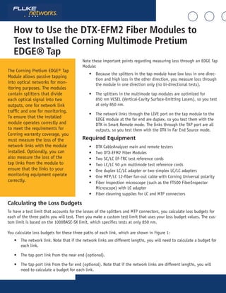
  • 1. How to Use the DTX-EFM2 Fiber Modules to Test Installed Corning Multimode Pretium EDGE® Tap Note these important points regarding measuring loss through an EDGE Tap Module: • Because the splitters in the tap module have low loss in one direc- tion and high loss in the other direction, you measure loss through the module in one direction only (no bi-directional tests). • The splitters in the multimode tap modules are optimized for 850 nm VCSEL (Vertical-Cavity Surface-Emitting Lasers), so you test at only 850 nm. • The network links through the LIVE port on the tap module to the EDGE module at the far end are duplex, so you test them with the DTX in Smart Remote mode. The links through the TAP port are all outputs, so you test them with the DTX in Far End Source mode. Required Equipment • DTX CableAnalyzer main and remote testers • Two DTX-EFM2 Fiber Modules • Two SC/LC EF-TRC test reference cords • Two LC/LC 50 μm multimode test reference cords • One duplex LC/LC adapter or two simplex LC/LC adapters • One MTP/LC 12-fiber fan-out cable with Corning Universal polarity • Fiber inspection microscope (such as the FT500 FiberInspector Microscope) with LC adapter • Fiber cleaning supplies for LC and MTP connectors The Corning Pretium EDGE® Tap Module allows passive tapping into optical networks for mon- itoring purposes. The modules contain splitters that divide each optical signal into two outputs, one for network link traffic and one for monitoring. To ensure that the installed module operates correctly and to meet the requirements for Corning warranty coverage, you must measure the loss of the network links with the module installed. Optionally, you can also measure the loss of the tap links from the module to ensure that the links to your monitoring equipment operate correctly. Calculating the Loss Budgets To have a test limit that accounts for the losses of the splitters and MTP connectors, you calculate loss budgets for each of the three paths you will test. Then you make a custom test limit that uses your loss budget values. The cus- tom limit is based on the 1000BASE-SX limit, which specifies tests at only 850 nm. You calculate loss budgets for these three paths of each link, which are shown in Figure 1: • The network link. Note that if the network links are different lengths, you will need to calculate a budget for each link. • The tap port link from the near end (optional). • The tap port link from the far end (optional). Note that if the network links are different lengths, you will need to calculate a budget for each link.
  • 2. B 6 1211 AB 5 109 AB 4 87 AB 3 6 PortTapModule PartNumber Serial MADEINMEXICO TAPLIVE 5 AB 2 43 AB 1 21 A WARRANTY VOID Link under test Pretium EDGE Tap Module Pretium EDGE Module B 6 1211 AB 5 109 AB 4 87 AB 3 6 PnPModule PartNumber Serial MADEINMEXICO 5 AB 2 43 AB 1 21 A WARRANTY VOID Do not disconnect the output port 2 4 AB 3 B 1 21 A B 2 3 B 1 21 A Do not disconnect the output port TRC TRC Near End Far End DTX in Smart Remote mode EF-TRC 2 EF-TRC 1 B 6 1211 AB 5 109 AB 4 87 AB 3 6 PortTapModule PartNumber Serial MADEINMEXICO TAPLIVE 5 AB 2 43 AB 1 21 A WARRANTY VOID Tap port fan-out cable (Corning Universal polarity) Pretium EDGE Tap Module Pretium EDGE Module B 6 1211 AB 5 109 AB 4 87 AB 3 6 PnPModule PartNumber Serial MADEINMEXICO 5 AB 2 43 AB 1 21 A WARRANTY VOID 11 1 Connect to even-numbered connectors Connect to odd-numbered connectors 9 7 5 3 2 4 6 8 10 12 Near End Far End DTX in Far End Source mode Do not disconnect the output port Smart remote with OUTPUT port transmitting at 850 nm (LED is solid red) EF-TRC
  • 3. B 6 1211 AB 5 109 AB 4 87 AB 3 6 PortTapModule PartNumber Serial MADEINMEXICO TAPLIVE 5 AB 2 43 AB 1 21 A WARRANTY VOID Link under test Pretium EDGE Tap Module Pretium EDGE Module B 6 1211 AB 5 109 AB 4 87 AB 3 6 PnPModule PartNumber Serial MADEINMEXICO 5 AB 2 43 AB 1 21 A WARRANTY VOID Do not disconnect the output port12 2 Connect to even-numbered connectors Connect to even-numbered connectors 10 8 6 4 12 10 8 6 4 2 Near End Far End Tap port fan-out cable (Corning Universal polarity) DTX in Far End Source mode Smart remote with OUTPUT port transmitting at 850 nm (LED is solid red) EF-TRC Component Maximum loss (dB)* OM4 EDGE trunk fiber 2.8 dB/km (0.00085 dB/ft) MTP® mated pair loss 0.35 LC mated pair loss 0.15 50/50 splitter inside the EDGE Tap Module 3.8 30/70 splitter inside the EDGE Tap Module 6.6/1.8 *Insertion loss when mated to other system components with similar performance specifications. Table 1 shows the values to use for your loss budget calculations.
  • 4. Figure 2 shows an example of a loss budget calculation for a test from the far end through the tap port and through a fan-out cable. Note that the loss of the LC connection at the end of the fan-out cable is not included in this ex- ample. The calculation includes the loss of a 600 m trunk fiber and a 10 m tap port fan-out cable: • Loss for 600 m of OM4 EDGE trunk fiber for a network link: 2.8 dB/km x .6 km = 1.68 dB • Loss for 10 m of OM4 EDGE trunk fiber for a tap port harness: 2.8 dB/km x .01 km = 0.028 dBB 6 1211 AB 5 109 AB 4 87 AB 3 6 PortTapModule PartNumber Serial MADEINMEXICO TAPLIVE 5 AB 2 43 AB 1 21 A WARRANTY VOID Tap port fan-out cable (Corning Universal polarity) Pretium EDGE Tap Module Pretium EDGE Module B 6 1211 AB 5 109 AB 4 87 AB 3 6 PnPModule PartNumber Serial MADEINMEXICO 5 AB 2 43 AB 1 21 A WARRANTY VOID 11 1 Connect to even-numbered connectors Connect to odd-numbered connectors 9 7 5 3 2 4 6 8 10 12 Near End Far End DTX in Far End Source mode Do not disconnect the output port Smart remote with OUTPUT port transmitting at 850 nm (LED is solid red) EF-TRC Figure 2. Example of a Loss Budget Calculation for Testing Network Links For more examples of loss budget calculations, see the Corning Standard Recommended Procedure (SRP) document number 003-126 on the Corning web site.
  • 5. Setting Up a Custom Test Limit Next, make a custom test limit that will include your loss budget values. The first loss budget value you enter will be for the first network link you will test. 1. Turn the rotary switch to SETUP. 2. Select Fiber Loss. 3. On the Fiber Loss screen, set the Remote End Setup to Smart Remote and set Bi-Directional to No. 4. Select Test Limit. 5. On the Test Limit screen, press F1 More, then select Custom. 6. Press F1 Create. 7. Select Name, enter a name for your limit, then press SAVE. 8. Select Use Default Values From. 9. On the Use Default Values From screen, select Application, then select 1000BASE-SX. 10. On the Custom screen, select Maximum Length. 11. Set the maximum length to a value that is longer than the longest trunk in the fiber network, then press SAVE. 12. On the Custom screen, select Maximum Loss at 850 nm. 13. Set the Maximum Loss at 850 nm to the calculated budget for the first network link you will test, then press SAVE. Note that if the network links are different lengths, you will need to change this value accordingly before you test each link. 14. On the Custom screen, press SAVE to save the custom limit. 15. Highlight your new custom limit, then press ENTER to select it. On the settings tabs of the Fiber Loss screen, select these settings: • Fiber Type: OM4 Multimode 50 • Number of Adapters/Number of Splices: Not used, since you will calculate the loss budget manually • Connector Type: LC • Test Method: 1 Jumper Testing the Network Links The network links are duplex connections, so you can use Smart Remote mode to test both fibers in each link. Set the Reference for Smart Remote Mode 1. Turn on the main and remote DTX testers and let them sit for 5 minutes. Allow additional time if the modules have been stored above or below ambient temperature. 2. Turn the rotary switch to SETUP, then select Fiber Loss. 3. Select Remote End Setup, then select Smart Remote. 4. Turn the rotary switch to SPECIAL FUNCTIONS, then select Set Reference. If both a fiber module and a twist- ed pair or coaxial adapter are attached, select Fiber Module next.
  • 6. 5. Clean and inspect the connectors on the tester, remote, and test reference cords. Connect the tester and remote as shown in Figure 3 for setting the reference. 6. Press TEST 7. The View Reference screen shows the reference values and the date and time the reference was set. For 50/125 μm, the reference values should be better than -24.50 dBm where -23.50 dBm is better than -24.50 dBm. If the values are good, press F2 OK. If not, clean all fiber connections and set the reference again. 8. Press F2 OK. Figure 3. Reference and TRC Test Connections for Smart Remote Mode EF-TRC 1 EF-TRC 2 EF-TRC 1 EF-TRC 2 TRC test connections Reference connections Additional TRC Additional TRC
  • 7. Next, verify that the test reference cords (TRCs) you will add are good: 1. Disconnect the test reference cords from the INPUT ports on the tester and smart remote. 2. Make the connections shown in Figure 3 for testing the TRCs. 3. Turn the rotary switch to AUTOTEST, then press TEST. 4. Press ENTER to see the test results. The loss for each fiber (Input Fiber and Output Fiber) in both directions must be no more than 0.15 dB at 850 nm. If the loss is too high, clean the connections you made for the TRC test and do the test again. Remember not to disconnect the fibers from the DTX output ports. If you do, you must set the reference again. 5. Save the test results to show that you used good test reference cords to test the fiber links. B 6 1211 AB 5 109 AB 4 87 AB 3 6 PortTapModule PartNumber Serial MADEINMEXICO TAPLIVE 5 AB 2 43 AB 1 21 A WARRANTY VOID Link under test Pretium EDGE Tap Module Pretium EDGE Module B 6 1211 AB 5 109 AB 4 87 AB 3 6 PnPModule PartNumber Serial MADEINMEXICO 5 AB 2 43 AB 1 21 A WARRANTY VOID Do not disconnect the output port 2 4 AB 3 B 1 21 A B 2 3 B 1 21 A Do not disconnect the output port TRC TRC Near End Far End DTX in Smart Remote mode EF-TRC 2 EF-TRC 1
  • 8. Testing the Tap Port Links It’s not necessary to test the tap port links to meet Corning’s requirements for warranty coverage, but you may want to do so to make sure your tap port links are good. Note that this article shows the TAP port connected to a Corning Universal polarity fan-out cable. You can also con- nect the TAP port to another Pretium EDGE module. In that case, you would add another MTP and LC mated pair loss to your loss budget, and you would connect the DTX tester to the LC ports in the module. TAP Port Connections When you connect the remote to the EDGE Tap module at the near end, you measure the tap port link’s loss at the odd numbered connectors on the tap port fan-out cable or EDGE module connected to the tap port. When you con- nect the remote to the EDGE module at the far end, you measure the tap port link’s loss at the even-numbered con- nectors on the tap port fan-out cable or EDGE module connected to the tap port. Figure 5 shows these connections. Figure 5. Connections from the Near and Far End Modules to the TAP Port Cable Set the Reference for Far End Source Mode Because all of the tap port connections are outputs, you will use Far End Source mode to test all the tap port links in the same direction, one at a time. Set the reference and test your test reference cords (TRCs) as follows: 1. Turn on the main and remote DTX testers and let them sit for 5 minutes. Allow additional time if the modules have been stored above or below ambient temperature.
  • 9. 2. Turn the rotary switch to SETUP, then select Fiber Loss. 3. Select Remote End Setup, then select Far End Source. 4. Clean and inspect the connectors on the tester, smart remote, and test reference cords. Connect the tester and smart remote as shown in Figure 6 for setting the reference. 5. On the smart remote, hold down the button next to the VFL port for approximately 3 seconds to turn on the OUTPUT port at 850 nm. The LED is red for 850 nm and green for 1300 nm. 6. Turn the rotary switch to SPECIAL FUNCTIONS, then select Set Reference. If both a fiber module and a twist- ed pair or coaxial adapter are attached, select Fiber Module next. 7. Press TEST. 8. The View Reference screen shows the reference value and the date and time the reference was set. For 50/125 μm, the reference value should be better than -24.50 dBm where -23.50 dBm is better than -24.50 dBm. If the value is good, press F2 OK. If not, clean all fiber connections and set the reference again. 9. Press F2 OK. Figure 6. Reference and TRC Test Connections for Far End Source Mode
  • 10. Next, verify that the test reference cord (TRC) you will add is good: 1. Disconnect the test reference cords from the INPUT port on the tester. 2. Make the connections shown in Figure 6 for testing the TRC. 3. Turn the rotary switch to AUTOTEST, then press TEST. 4. Press ENTER to see the test results. The loss must be no more than 0.15 dB at 850 nm. If the loss is too high, clean the connections you made for the TRC test and do the test again. Remember not to disconnect the fiber from the remote’s output port. If you do, you must also set the reference again. 5. Save the test results to show that you used a good test reference cord to test the fiber links. Test the Tap Port Links from the Near End 1. Change the value for the Maximum Loss at 850 nm in your custom limit to the applicable loss budget value for the fiber path from the near end through the tap port. 2. Clean and inspect the even-numbered LC connectors on the EDGE Tap module (near end) and the odd-num- bered connectors on the tap port fan-out cable or third EDGE module. 3. Make the connections shown in Figure 7 if you will do the test through a fan-out cable, or in Figure 8 if you will do the test through a third EDGE module. 4. Make sure the smart remote’s OUTPUT port is still transmitting at 850 nm (LED is solid red). 5. Turn the rotary switch to AUTOTEST, then press ENTER. 6. If the test passes, save the results. If it fails, clean and inspect the connections again, or troubleshoot as necessary, then test again. 7. Repeat steps 3-6 for all tap port links.
  • 11. B 6 1211 AB 5 109 AB 4 87 AB 3 6 PortTapModule PartNumber Serial MADEINMEXICO TAPLIVE 5 AB 2 43 AB 1 21 A WARRANTY VOID Tap port fan-out cable (Corning Universal polarity) Pretium EDGE Tap Module Pretium EDGE Module B 6 1211 AB 5 109 AB 4 87 AB 3 6 PnPModule PartNumber Serial MADEINMEXICO 5 AB 2 43 AB 1 21 A WARRANTY VOID 11 1 Connect to even-numbered connectors Connect to odd-numbered connectors 9 7 5 3 2 4 6 8 10 12 Near End Far End DTX in Far End Source mode Do not disconnect the output port Smart remote with OUTPUT port transmitting at 850 nm (LED is solid red) EF-TRC Figure 7. Connections for Testing the Tap Port Links from the Near End through a Fan-Out Cable
  • 12. EF-TRC B 6 1211 AB 5 109 AB 4 87 AB 3 6 PortTapModule PartNumber Serial MADEINMEXICO TAPLIVE 5 AB 2 43 AB 1 21 A WARRANTY VOID Link under test Pretium EDGE Tap Module Pretium EDGE Module B 6 1211 AB 5 109 AB 4 87 AB 3 6 PnPModule PartNumber Serial MADEINMEXICO 5 AB 2 43 AB 1 21 A WARRANTY VOID Do not disconnect the output port Connect to even-numbered connectors 12 10 8 6 4 2 Near End Far End 12 2 108 64 B 6 12 11 A B 5 10 9 A B 4 8 7 A B 3 6 PnP M od ule Par t Num be r Ser ial MA DE IN ME XI CO 5 A B 2 4 3 A B 1 2 1 A WAR RANTY VOID Connect to even-numbered connectors DTX in Far End Source mode Pretium EDGE Module TRC Smart remote with OUTPUT port transmitting at 850 nm (LED is solid red) Figure 8. Connections for Testing the Tap Port Links from the Near End through an EDGE Module
  • 13. Test the Tap Port Links from the Far End 1. Change the value for the Maximum Loss at 850 nm in your custom limit to the applicable loss budget value for the first tap port link you will test from the far end through the tap port. 2. Clean and inspect the even-numbered LC connectors on the EDGE module (far end) and the even-numbered- connectors on the tap port fan-out cable or third EDGE module. 3. Make the connections shown in Figure 9 if you will do the test through a fan-out cable, or in Figure 10 if you will do the test through a third EDGE module. 4. Make sure the smart remote’s OUTPUT port is still transmitting at 850 nm (LED is solid red). 5. Turn the rotary switch to AUTOTEST, then press ENTER. 6. If the test passes, save the results. If it fails, clean and inspect the connections again, or troubleshoot as necessary,then test again. 7. If the network links are different lengths, change the value for the Maximum Loss at 850 nm in your custom limit to the applicable loss budget value for the next tap port link. 8. Repeat steps 3-7 for all the tap port links. B 6 1211 AB 5 109 AB 4 87 AB 3 6 PortTapModule PartNumber Serial MADEINMEXICO TAPLIVE 5 AB 2 43 AB 1 21 A WARRANTY VOID Link under test Pretium EDGE Tap Module Pretium EDGE Module B 6 1211 AB 5 109 AB 4 87 AB 3 6 PnPModule PartNumber Serial MADEINMEXICO 5 AB 2 43 AB 1 21 A WARRANTY VOID Do not disconnect the output port12 2 Connect to even-numbered connectors Connect to even-numbered connectors 10 8 6 4 12 10 8 6 4 2 Near End Far End Tap port fan-out cable (Corning Universal polarity) DTX in Far End Source mode Smart remote with OUTPUT port transmitting at 850 nm (LED is solid red) EF-TRC Figure 9. Connections for Testing the Tap Port Links from the Far End through a Fan-Out Cable
  • 14. EF-TRC B 6 1211 AB 5 109 AB 4 87 AB 3 6 PortTapModule PartNumber Serial MADEINMEXICO TAPLIVE 5 AB 2 43 AB 1 21 A WARRANTY VOID Link under test Pretium EDGE Tap Module Pretium EDGE Module B 6 1211 AB 5 109 AB 4 87 AB 3 6 PnPModule PartNumber Serial MADEINMEXICO 5 AB 2 43 AB 1 21 A WARRANTY VOID Do not disconnect the output port Connect to even-numbered connectors 12 10 8 6 4 2 Near End Far End 12 2 108 64 B 6 12 11 A B 5 10 9 A B 4 8 7 A B 3 6 PnP M od ule Par t Num be r Ser ial MA DE IN ME XI CO 5 A B 2 4 3 A B 1 2 1 A WAR RANTY VOID Connect to even-numbered connectors DTX in Far End Source mode Pretium EDGE Module TRC Smart remote with OUTPUT port transmitting at 850 nm (LED is solid red) Figure 10. Connections for Testing the Tap Port Links from the Far End through an EDGE Module