Download to read offline
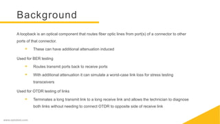
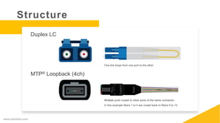
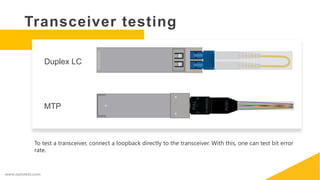


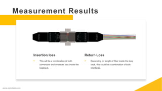


Loopbacks are optical components that route fiber optic lines from ports of a connector back to other ports of the same connector. They are used for bit error rate testing and OTDR testing of links. To test a transceiver using a loopback, connect the loopback directly to the transceiver and test the bit error rate. Equipment needed includes an IL system, RL meter, and fanouts or cords with sufficient channel counts to match the loopback. Measurements of insertion loss and return loss made using loopbacks provide information about connector and fiber loss across the looped link.


