SlideShare a Scribd company logo
1 of 307
from the channel center, so that they actually consume five
overlapping channels (for example,
transmitting on channel 6 may cause interference on channels 5
and 7 as well as limited on
channels 4 and 8). This leaves only three nonoverlapping
(simultaneously usable) 20-MHz
channels: 1, 6, and 11. IEEE 802.11a networks have 555 MHz
spread across 23 nonover-
lapping channels.
Channel allocation is covered in Chapter 5.
Managing the radio frequency spectrum of 802.11b/g—and to a
lesser degree
802.11a—wireless networks can be challenging. Setting all of
the APs to the same channel
number would result in reduced throughput because each station
must wait a longer period
of time for its turn to transmit (called cochannel interference).
To eliminate this interference
it is necessary to arrange the coverage areas of the APs so that
one channel does not interfere
with an adjacent channel. In Figure 7-6, only channels 1, 6 and
11 are used as nonoverlap-
ping channel numbers. Each cell is separated from other cells so
that no two adjacent cells
have the same channel number in order to reduce interference
(known as adjacent channel
interference). This type of WLAN is called a multiple-channel
architecture or MCA because
more than one channel is in the wireless network.
One of the keys to an MCA is to have the correct cell size in
order to minimize adjacent
channel interference. This is especially true when “scaling” or
adding additional capacity to
the WLAN. The most common approach, called the micro-cell
architecture, creates small
areas of coverage. Typically, in order to add wireless network
capacity, more APs are added
while the transmission power of all APs is reduced to minimize
potential interference. This
can usually provide acceptable network throughput if the site
has been properly surveyed to
identify the best locations for the APs. In addition, the
configuration of BSSIDs and ESSIDs
can be made easier in a micro-cell architecture.
Single-Channel Architecture (SCA)
The fundamental reason why multiple APs in a MCA are
necessary is because the interference
range of wireless devices exceeds their useful communication
range. That is, devices that are
too far apart to communicate can still be close enough to
interfere with each other. An alter-
native to MCA that addresses this weakness is the single-
channel architecture (SCA). Instead
of having each cell use a different channel as in WCA, WLANs
using SCA have all of the APs
use the same channel. Each AP has overlapping coverage that
forms a continuous region on a
single channel, thereby reducing interference. The SCA
architecture is accomplished through
6 1 11 116 1
11 6 1 11 6 1
6 1 11 116 1
11 6 1 11 6 1
Figure 7-6 Nonoverlapping cells
© Cengage Learning 2013
256 Chapter 7 WLAN Management and Architectures
Copyright 2012 Cengage Learning. All Rights Reserved. May
not be copied, scanned, or duplicated, in whole or in part. Due
to electronic rights, some third party content may be suppressed
from the eBook and/or eChapter(s).
Editorial review has deemed that any suppressed content does
not materially affect the overall learning experience. Cengage
Learning reserves the right to remove additional content at any
time if subsequent rights restrictions require it.
7
the use of lightweight APs and WLCs. Each lightweight AP
broadcasts the same virtual BSSID
(instead of multiple BSSIDs) and each has the same configured
MAC address. This also serves
to eliminate the cochannel interference problem.
There are several advantages to SCA. The first advantage is
smoother handoffs. A mobile sta-
tion must receive an uninterrupted flow of frames when moving
from the coverage area of one
AP to another AP, especially when using VoIP. With MCA, the
station responsible for this pro-
cedure monitors the signal strength from multiple APs or data
frame error rates. With SCA, the
handoff is instead accomplished through coordination between
the lightweight APs and the
WLC. The stations cannot distinguish which AP is providing the
coverage; instead, the net-
work decides which AP should transmit and receive data for a
particular station. This means
that the stations are not involved in any handoff decision from
one AP to another. As stations
move, the network directs traffic to them via the nearest AP
with available capacity.
With SCA, the roaming clients are “fooled” into thinking that
they
are always interacting with the same AP when in reality they
may be
communicating with several different APs.
A second advantage to SCA is that the often tedious planning
process required for MCA
WLANs is no longer needed. All APs are set to the same
common RF channel and transmit
power, eliminating the need for lengthy and often complex
planning regarding the location
and unique configuration of each AP.
Another advantage to SCA is that because each AP is operating
on the same channel, cochan-
nel interference is no longer an issue. This can also improve the
signal-to-noise ratio (SNR)
that in turn increases throughput and reliability.
A final advantage is that the SCA architecture provides more
network information in order
to make informed decisions. With MCA, a station and AP are
essentially “in the dark”
regarding the overall status of the network. Yet with SCA a
more complete knowledge of
the conditions at neighboring APs, and even historical
information about how stations
reacted previously when in similar situations, can be used when
deciding which AP a roam-
ing client should be associated with.
MCA is similar to the centralized handover control of first-
generation
cellular telephone networks, while today’s 3G and 4G is based
on a
shared network-client responsibility like SCA.
SCA can also support channel stacking. Channel stacking allows
for increased capacity by hav-
ing more than one SCA operating in an area. Instead of havi ng
only one SCA on channel 1,
another set of APs operating on channel 6 can also be added
using a different BSSID. Stations
can then associate with either SCA, thus dramatically increasing
the available capacity. This
additional capacity can be used for redundancy or to support
higher data rates or user density.
Instead of installing additional APs, channel stacking can also
be
accomplished by using APs that support multiple radios.
Multiple-Channel Architecture vs. Single-Channel Architecture
Models 257
Copyright 2012 Cengage Learning. All Rights Reserved. May
not be copied, scanned, or duplicated, in whole or in part. Due
to electronic rights, some third party content may be suppressed
from the eBook and/or eChapter(s).
Editorial review has deemed that any suppressed content does
not materially affect the overall learning experience. Cengage
Learning reserves the right to remove additional content at any
time if subsequent rights restrictions require it.
Wireless Network Management Systems (WNMS)
C W N A
4.4.4. Define, describe, and implement a WNMS that manages
autonomous APs, WLAN controllers, and mesh nodes.
A wireless network management system (WNMS) is a set of
hardware and/or software that can
be used to provide unified management of a wireless network.
This includes configuration man-
agement, deployment, and especially troubleshooting. A WNMS
can be used to isolate and solve
wireless problems, which can have many different root causes
(station wireless configuration
errors, authentication problems, connectivity issues, problems
with wired ports or switches, etc.).
The typical features of a WNMS include:
● Configuration management. A new or updated configuration
can be “pushed” out to
all wireless devices, a single device, or a group of specific
devices. These configurations
can be designed so that general updates do not override specific
configuration settings
unique to each device.
● Firmware/Software distribution. As new firmware and
software is made available,
these can be distributed to all devices from a central
management facility, with no need
to “touch” each device.
● Intelligent scheduling. To minimize the impact of a new
configuration or firmware
update, many WNMS can be scheduled to automatically occur
late at night or on the
weekends when the wireless network usage is low. In addition,
recurring tasks can be
scheduled to automatically occur on a regular daily, weekly, or
monthly basis.
● User and device monitoring. A WNMS can locate a specific
user or device on a wire-
less network often by WLAN administrator clicking a single
button on a Web-based
software interface. This allows a wireless technician to monitor
historical information
and use special diagnostic information to address problems.
One of the disadvantages of a WNMS is that it cannot be used
to
monitor wireless network traffic as it occurs.
Power Management
C W N A
3.1.3. Explain and apply the power management features of
WLANs.
Most stations in a WLAN are portable laptop or tablet
computers, giving the users the
freedom to roam without being tethered to the network by wires.
These devices depend upon
batteries as their primary power source when they are mobile.
To conserve battery power,
258 Chapter 7 WLAN Management and Architectures
Copyright 2012 Cengage Learning. All Rights Reserved. May
not be copied, scanned, or duplicated, in whole or in part. Due
to electronic rights, some third party content may be suppressed
from the eBook and/or eChapter(s).
Editorial review has deemed that any suppressed content does
not materially affect the overall learning experience. Cengage
Learning reserves the right to remove additional content at any
time if subsequent rights restrictions require it.
7
laptops are usually configured to go into a “sleep” mode after a
specific period of time, when
functions such as the hard drive or display screen are
temporarily powered down by the
computer.
However, a laptop that is part of a WLAN must remain “awake”
in order to receive wireless
network transmissions. If a laptop is in sleep mode, it could
miss important transmitted infor-
mation or even lose the network connection altogether. The
dilemma is how to allow the lap-
top to power down into sleep mode during idle periods to
preserve battery life yet continue to
be active to receive network transmissions.
The reason a wireless laptop must continue to remain awake to
receive
network transmissions is because the original IEEE 802
standard assumes
that stations are always ready to receive a network message.
The answer to the problem is known as power management.
Power management allows a
station to be in either active mode when it is continuously
awake or in power save mode,
which turns off the wireless network interface card adapter to
conserve battery life but still
not miss wireless transmissions. Power management is
transparent to all protocols and appli-
cations so that it will not interfere with normal network
functions.
Power save mode is also called continuous aware mode or
constantly
awake mode.
IEEE 802.11 power management can be divided into two
categories: basic power manage-
ment and enhanced power management techniques.
Basic Power Management
In a BSS infrastructure WLAN, the steps of power save mode
are as follows:
1. A station sends a frame to the AP with the Power
Management field set to 1 to indicate
that it will go into power save mode after this frame
transmission.
2. The AP records that the station is in power save mode to
prevent any frames from being
sent to that station from the AP.
3. As the AP receives frames specifically for that station
(unicast frames) it temporarily
stores those frames at the AP (buffering).
4. At prescribed set times, the AP will send out a beacon frame
to all stations. At the same
time, all stations switch to active mode to receive the frame.
This frame contains a list of
the stations that have buffered unicast frames waiting at the AP.
This list is known as
the traffic indication map (TIM).
5. If a station learns from the TIM that buffered frames are
waiting for it, that station will
request the AP to have those frames forwarded (if it has no
buffered frames then it can
return to power save mode). Once the buffered frames are
received the station can again
return to power save mode. This is illustrated in Figure 7-7.
Power Management 259
Copyright 2012 Cengage Learning. All Rights Reserved. May
not be copied, scanned, or duplicated, in whole or in part. Due
to electronic rights, some third party content may be suppressed
from the eBook and/or eChapter(s).
Editorial review has deemed that any suppressed content does
not materially affect the overall learning experience. Cengage
Learning reserves the right to remove additional content at any
time if subsequent rights restrictions require it.
The amount of power that a wireless network interface card
adapter
consumes is significant. One typical card requires 450
millionths of
an amp (mA) to transmit and 270 mA to receive. While in power
save mode it only consumes 15 mA.
When a station in power save mode must receive a frame
intended for all stations (multicast
or broadcast frame) the AP will send a special TIM called a
delivery traffic indication
message (DTIM). All stations will then change to active mode
to receive the frame.
Power management for an IBSS is different because there is no
AP. Every station in an IBSS
must buffer the frames that it attempts to send to another device
in case the receiving device
is asleep. At a specific period of time, known as the ad hoc
traffic indication message
(ATIM) window, each station must be awake. At this time a
station sends a beacon frame
to all other stations. Those stations that previously attempted to
send a frame to a sleeping
station will now send an ATIM frame, which indicates that the
receiving station has pending
data to be received and must remain awake (any device that
does not receive an ATIM frame
can go back to sleep). Finally, the data frames are retrieved
from the buffer and sent to the
station that is now awake.
There are a variety of configuration settings that can be used
with
power management. For example, different power save levels
can be
specified for a station in power save mode. One level may
require that a
station turn off the radio for as long as possible without losing
network
connectivity for the greatest power savings at the sake of
network per-
formance, while another setting can require that the station turn
off the radio for small periods in
order to provide optimal network performance.
Enhanced Power Management
Although the basic power management features can provide
power savings, there are
enhanced power management technologies that can provide
additional functionality and
Station A
Power save mode
Power save mode
Active mode
Station B
Station C TIM
Station
A
Yes
Station
C
No Access point
Send frames request
Figure 7-7 Request for frames
© Cengage Learning 2013
260 Chapter 7 WLAN Management and Architectures
Copyright 2012 Cengage Learning. All Rights Reserved. May
not be copied, scanned, or duplicated, in whole or in part. Due
to electronic rights, some third party content may be suppressed
from the eBook and/or eChapter(s).
Editorial review has deemed that any suppressed content does
not materially affect the overall learning experience. Cengage
Learning reserves the right to remove additional content at any
time if subsequent rights restrictions require it.
7
power savings. These include Unscheduled Automatic Power
Save Delivery, Power Save
Multi-Poll, and Spatial Multiplexing Power Save.
Unscheduled Automatic Power Save Delivery (U-APSD) The
Unscheduled
Automatic Power Save Delivery (U-APSD), which is similar to
the Wi-Fi Alliance’s WMM
Power-Save (WMM-PS), is often used when a wireless station is
using VoIP. With the basic
power management settings a device using VoIP for a voice
conversation may receive frames
every 10–20 milliseconds (ms), while an AP usually sends out a
beacon frame every 100 ms.
Because the delay is too long, normally a station using VoIP
simply could not afford to go
into power save mode.
With U-APSD, the station would inform the AP that it is
operating according to this proto-
col, and the AP will then save any frames destined for this
station. However, instead of
waiting for the AP to send a beacon frame to all stations as with
basic power management,
whenever the AP sees a frame coming from the station it will
immediately release any frames
it has been holding for the station. This allows the station to
sleep until it needs to send a
VoIP frame to the AP, and that frame also serves as an indicator
to release any packets des-
tined for it. Once the station has received its frames it then goes
back into power save mode.
There is a slight delay for the station in listen mode when using
VoIP
with U-APSD while the AP gathers up and sends the frames, at
which time the station goes into receive mode.
U-APSD improves the efficiency of the basic power
management in two ways: it increases
the amount of time that a station can be in power save mode and
it decreases the number
of frames that a station must send and receive in order to
download stored frames on the
AP. An interesting benefit of U-APSD is that, when higher data
rates are used, overall
power savings increase. This is because a station will spend less
time actively transmitting
and receiving and will spend more time in power save mode.
A device using U-APSD for VoIP consumes approximately one-
sixth of
the power compared with not using U-APSD.
Power Save Multi-Poll (PSMP) Another enhanced power
management mechanism is
the Power Save Multi-Poll (PSMP), which can have either a
scheduled or an unscheduled
component. Scheduled PSMP (S-PSMP) allows an AP to send a
transmission schedule to one
or more stations in a WLAN. This schedule informs the stations
when they should be in active
mode to receive frames as well as when they are allowed to
begin transmitting. And since a
station can only send or receive frames based on the schedule,
other stations cannot interfere
with the transmissions by attempting to send simultaneously. By
using a schedule, stations
can be in power save mode for the maximum amount of time
without missing any frames.
Unscheduled PSMP (U-PSMP) functionality does not replace U-
APSD
(WMM), but rather extends it to add further functionality.
Power Management 261
Copyright 2012 Cengage Learning. All Rights Reserved. May
not be copied, scanned, or duplicated, in whole or in part. Due
to electronic rights, some third party content may be suppressed
from the eBook and/or eChapter(s).
Editorial review has deemed that any suppressed content does
not materially affect the overall learning experience. Cengage
Learning reserves the right to remove additional content at any
time if subsequent rights restrictions require it.
Although an improvement over basic power management, S-
PSMP still requires a significant
amount of overhead. In addition, stations may not be able to be
in power save mode for
extended periods of time. For example, with VoIP transmissions
the time gap for station
may be so short that the station must still remain in active mode
while other stations are
receiving their VoIP packets. Generally speaking, P-SPMP is
used only if the number of sta-
tions using VoIP associated with a single AP exceeds 15. If
fewer than 15 stations are using
VoIP, then U-APSD should be used instead.
Spatial Multiplexing Power Save (SMPS) Spatial Multiplexing
Power Save
(SMPS) can be used with IEEE 802.11n devices using Multiple-
Input Multiple-Output
(MIMO). A device using MIMO may have a 2x3:2 configuration
of two transmit antennas
and three receive antennas (along with two data spatial
streams), each having its own radio
chain. Yet it is not necessary for all three of the receive radio
chains to be simultaneously
awake. This is because the station is only waiting to receive a
low data rate beacon that
may not be sent with MIMO encoding.
SMPS allows the station to change from a 2x3:2 configuration
to a 1x1:1 to save power. If
the station is plugged into an electrical outlet running on
alternating current (AC), it can be
configured to run using all radio chains (since conserving power
is not a concern). However,
if the station begins running on a direct current (DC) battery, it
will automatically “down-
shift” to 1x1:1 while waiting to receive beacons. The station
would then “upshift” back to
2x3:2 when necessary.
SMPS is also called Dynamic MIMO Power Save.
A device using SMPS can downshift and then tell the AP to
prevent it from sending any
MIMO-encoded frames to the device with only one receive radio
chain. The AP can then
send a request to send (RTS) packet that indicates the AP is
about to send a MIMO packet
so that the device can upshift to receive it.
The power savings provided by SMPS can be significant. The
ability
to dynamically change the MIMO configuration can reduce
power
consumption by 30 percent when the traffic is low.
Chapter Summary
■ The most common type of wireless architecture is an
autonomous access point archi-
tecture. Each AP is independent or autonomous from all other
APs. There are several
enhanced features in this type of architecture. Two of the most
advanced features are
Quality of Service (QoS) and wireless virtual LANs (VLANs).
QoS provides the ability
to prioritize different types of frames so that those frames that
are more time-dependent,
such as voice and video, can be given a higher priority (and
arrive earlier) than
standard data frames. A wireless VLAN is often used to
segment traffic. Wireless
262 Chapter 7 WLAN Management and Architectures
Copyright 2012 Cengage Learning. All Rights Reserved. May
not be copied, scanned, or duplicated, in whole or in part. Due
to electronic rights, some third party content may be suppressed
from the eBook and/or eChapter(s).
Editorial review has deemed that any suppressed content does
not materially affect the overall learning experience. Cengage
Learning reserves the right to remove additional content at any
time if subsequent rights restrictions require it.
7
VLANs can be configured in one of two ways. The difference
depends upon which
device separates the packets and directs them to different
networks.
■ A controller-based architecture uses a wireless LAN
controller (WLC) to manage and
provide configuration services to the WLAN. Access points in a
controller-based
architecture are significantly different. A lightweight access
point does not contain the
management and configuration functions that are found in
autonomous access points;
instead, these features are contained in the centralized WLC.
Lightweight access points
only have simplified radios for wireless communication between
devices and a media
converter for accessing the wired network. A lightweight mesh
AP can be used instead
of a standard mesh AP. Lightweight mesh APs can also be
centrally configured and
managed through a WLC. A captive portal AP uses a standard
Web browser to pro-
vide information, give the wireless user the opportunity to agree
to a policy, or present
valid login credentials. The WLC is a device that can be
centrally configured; these
settings are then automatically distributed to all lightweight
access points.
■ Besides autonomous access point architectures and control -
based architectures, there
are other types of WLANs. A WLAN array is a proprietary
product that resembles a
round consumer-grade smoke detector and replaces a standard
WLC installed in a
rack in a server closet. The WLAN array contains a WLC that
can be directly con-
nected to as many as 16 integrated access points. Cooperative
control is another
proprietary technology marketed architecture that enables APs
to communicate and
coordinate with each other without the need for a WLC, so that
each AP contains
the capabilities of a WLC. Wireless mesh access points
communicate wirelessly with
the next closest mesh access point.
■ A multiple-channel architecture, or MCA, has more than one
channel in the wireless
network. Each cell is separated from other cells so that no two
adjacent cells have the
same channel number in order to reduce interference. An
alternative to MCA is the
single-channel architecture (SCA). Instead of having each cell
use a different channel as
in WCA, WLANs using SCA have all of the APs use the same
channel. Each AP has
overlapping coverage that forms a continuous region on a single
channel, thereby
reducing interference. The SCA architecture is accomplished
through the use of
lightweight APs and WLCs.
■ A wireless network management system (WNMS) is a set of
hardware and/or software
that can be used to provide unified management of a wireless
network. This includes
configuration management, deployment, and especially
troubleshooting. A WNMS can
be used to isolate and solve wireless problems, which can have
many different root
causes (station wireless configuration errors, authentication
problems, connectivity
issues, problems with wired ports or switches, etc.).
■ Power management allows a station to be in either active
mode (continuously awake)
or in power save mode (turns off the wireless network interface
card adapter to con-
serve battery life but still not miss wireless transmissions).
Power management is
transparent to all protocols and applications so that it will not
interfere with normal
network functions. Basic power management involves the AP
temporarily storing
frames and then releasing them to the stations. Although the
basic power management
features can provide power savings, there are enhanced power
management technolo-
gies that can provide additional functionality and power
savings. With Unscheduled
Automatic Power Save Delivery (U-APSD) a station informs the
AP that it is operating
Chapter Summary 263
Copyright 2012 Cengage Learning. All Rights Reserved. May
not be copied, scanned, or duplicated, in whole or in part. Due
to electronic rights, some third party content may be suppressed
from the eBook and/or eChapter(s).
Editorial review has deemed that any suppressed content does
not materially affect the overall learning experience. Cengage
Learning reserves the right to remove additional content at any
time if subsequent rights restrictions require it.
according to this protocol, and the AP will then save any frames
destined for this
station. Whenever the AP sees a frame coming from the station,
it will immediately
release any frames it has been holding for the station. Power
Save Multi-Poll (PSMP)
allows an AP to send a transmission schedule to one or more
stations in a WLAN.
This schedule informs the stations when they should be in
active mode to receive
frames as well as when they are allowed to begin transmitting.
Spatial Multiplexing
Power Save (SMPS) allows a station to change from a MIMO
configuration to a single
radio in order to conserve power.
Key Terms
active mode A power management state in which the station is
continuously awake.
ad hoc traffic indication message (ATIM) window A specific
period of time that each
station must be awake.
adjacent channel interference Each cell is separated from other
cells so that no two
adjacent cells have the same channel number in order to reduce
interference.
captive portal AP An AP that uses a standard Web browser to
provide information, give
the wireless user the opportunity to agree to a policy, or present
valid login credentials.
channel stacking A technology that allows for increased
capacity by having more than one
SCA operating in an area.
cloud management Connecting wireless devices together using
the Internet in order to
remotely manage them.
cochannel interference Reduced throughput caused as a result of
all of APs set to the
same channel number.
cooperative control A proprietary product in which each AP
contains the capabilities of a
WLC.
delivery traffic indication message (DTIM) A special TIM sent
by an AP that is used when
a station in power save mode must receive a frame intended for
all stations.
distributed WLAN architecture A wireless architecture
configuration in which multiple
APs form a non-centralized network through a wireless
connection.
IEEE 802.11e-2005 The IEEE QoS standards.
IEEE 802.1q An IEEE standard for marking VLAN packets.
lightweight mesh AP A mesh AP that is centrally configured
and managed through a
WLC.
micro-cell architecture A wireless architecture that creates
small areas of coverage.
multiple-channel architecture (MCA) A wireless architecture in
which more than one
channel is used in the wireless network.
power management A technology that allows a WLAN to
conserve power.
power save mode A power management state in which the
station turns off the wireless
network interface card adapter to conserve battery life.
Power Save Multi-Poll (PSMP) An enhanced power management
technology that can have
either a scheduled or an unscheduled component.
Quality of Service (QoS) Prioritizing different types of frames
over a network.
264 Chapter 7 WLAN Management and Architectures
Copyright 2012 Cengage Learning. All Rights Reserved. May
not be copied, scanned, or duplicated, in whole or in part. Due
to electronic rights, some third party content may be suppressed
from the eBook and/or eChapter(s).
Editorial review has deemed that any suppressed content does
not materially affect the overall learning experience. Cengage
Learning reserves the right to remove additional content at any
time if subsequent rights restrictions require it.
7
Scheduled PSMP (S-PSMP) An enhanced power management
technology in which the AP
sends a transmission schedule to one or more stations in a
WLAN.
single-channel architecture (SCA) An architecture in which all
of the APs use the same
channel.
SNMP (Simple Network Management Protocol) A management
protocol that provides
information such as the number of bytes transmitted and
received, the number of frames
transmitted and received, the number of errors, and port status.
Spatial Multiplexing Power Save (SMPS) An enhanced power
management technology
that turns off MIMO radios.
split MAC A division in which lightweight APs only handle the
real-time layer functions
while MAC functionality is processed by the WLC.
total cost of ownership (TCO) The total cost of owning a
product, including acquisition,
setup, support, ongoing maintenance, service, and all operating
expenses.
traffic indication map (TIM) A list of stations that have
buffered unicast frames waiting at
the AP.
trunking A single cable is used to support multiple virtual
LANs.
Unscheduled Automatic Power Save Delivery (U-APSD) A
technology in which whenever
the AP sees a frame coming from the station it will immedi ately
releases any frames it has
been holding for the station.
virtual local area network (VLAN) A logical grouping of
network devices within a larger
physical network.
Voice over IP (VoIP) A telephony system that uses Internet
Protocol (IP-based) data packet
switching networks to transmit voice communications.
Wi-Fi Multimedia (WMM) A QoS specification created in 2004
by the Wi-Fi Alliance
modeled after a wired network QoS prioritization scheme.
wireless network management system (WNMS) A set of
hardware and/or software that
can be used to provide unified management of a wireless
network.
wireless switch Another name for a WLAN controller.
wireless VLANs A wireless virtual LAN typically used to
segment traffic.
WLAN array A proprietary product marketed that contains a
WLC that can be directly
connected to as many as 16 integrated APs.
WLAN profile A set of specific configurations that can be
applied to different wireless stations.
WMM Power-Save (WMM-PS) A technology that is similar to
Unscheduled Automatic
Power Save Delivery (U-APSD).
Review Questions
1. In an autonomous access point the “intelligence” for wireless
management, authentica-
tion, and encryption is contained in which device?
a. wireless network interface card adapter
b. WLC
c. station
d. access point
Review Questions 265
Copyright 2012 Cengage Learning. All Rights Reserved. May
not be copied, scanned, or duplicated, in whole or in part. Due
to electronic rights, some third party content may be suppressed
from the eBook and/or eChapter(s).
Editorial review has deemed that any suppressed content does
not materially affect the overall learning experience. Cengage
Learning reserves the right to remove additional content at any
time if subsequent rights restrictions require it.
2. Each of the following is a feature found in an autonomous
access point except:
a. support for Wireless Distribution Systems (WDS).
b. quality of service.
c. adjustable transmit power.
d. WLC.
3. The capability to prioritize different types of frames is known
as .
a. VoIP
b. Quality of Service (QoS)
c. Wi-Fi Prioritization (WFP)
d. IEEE 802.15f
4. The most flexible approach for separating packets and
directing them to different
networks in a wireless VLAN is to use the network .
a. access point (AP)
b. switch
c. hub
d. router
5. What is a split MAC architecture?
a. A lightweight AP that handles only the real-time MAC layer
functions in itself while
all other functions are processed by the WLC
b. A WLC that has two MAC addresses
c. A VoIP WLAN that uses a different MAC for each station
d. A wireless network interface card adapter that can change its
MAC address
6. Each of the following can be used by a captive portal AP
except:
a. advertisement.
b. encryption.
c. general authentication.
d. agree to an Acceptable Use Policy.
7. Which of the following is not a recognized functional area of
a network?
a. core layer
b. distribution layer
c. station layer
d. access layer
8. A is a set of specific configurations that can be applied to
different
wireless stations.
a. WLAN profile
b. management configuration
266 Chapter 7 WLAN Management and Architectures
Copyright 2012 Cengage Learning. All Rights Reserved. May
not be copied, scanned, or duplicated, in whole or in part. Due
to electronic rights, some third party content may be suppressed
from the eBook and/or eChapter(s).
Editorial review has deemed that any suppressed content does
not materially affect the overall learning experience. Cengage
Learning reserves the right to remove additional content at any
time if subsequent rights restrictions require it.
7
c. WLC frame
d. data resource package (DRP)
9. A WLAN array .
a. is only a prototype and has not yet been developed for actual
use
b. can only be used on a mesh network
c. uses multiple HiveAPs to share load balancing
d. contains a WLC that can be directly connected to as many as
16 integrated access
points
10. Which is not true regarding a multiple-channel architecture
configuration?
a. Cochannel interference can be a significant problem.
b. With IEEE 802.11b/g there are only three nonoverlapping
channels.
c. Each cell must be separated from other cells so that no two
adjacent cells have the
same channel number.
d. WLCs cannot be used in a multiple-channel architecture.
11. A WLAN that uses a single-channel architecture has each
AP .
a. using the same channel number
b. in a mesh network
c. in a closed array configuration
d. using higher power levels to send the signal farther
12. Channel stacking .
a. can only be used with MCA
b. is restricted to WLAN array configurations
c. uses more than one SCA in an area
d. is illegal in the United States
13. A set of hardware and/or software that can be used to
provide unified management of a
wireless network is called a .
a. configuration manager
b. Unified Software System
c. Wireless LAN Controller (WLC)
d. wireless network management system (WNMS)
14. Which of the following is not a step of the power save mode
in basic power manage-
ment in a BSS?
a. A station sends a frame to the AP with the Power
Management field set to 1 to
indicate that it will go into power save mode after this frame
transmission.
b. The user must manually put the wireless network card
interface adapter into power
save mode.
Review Questions 267
Copyright 2012 Cengage Learning. All Rights Reserved. May
not be copied, scanned, or duplicated, in whole or in part. Due
to electronic rights, some third party content may be suppressed
from the eBook and/or eChapter(s).
Editorial review has deemed that any suppressed content does
not materially affect the overall learning experience. Cengage
Learning reserves the right to remove additional content at any
time if subsequent rights restrictions require it.
c. As the AP receives frames specifically for that station it
temporarily stores those
frames at the AP.
d. At prescribed set times the AP will send out a beacon frame
to all stations.
15. What is a traffic indication map (TIM)?
a. a list of the stations that have buffered unicast frames waiting
at the AP
b. the route that frames take when transmitted from the AP to a
station
c. the congestion that results from too many stations in a micro
cell
d. a grid on a mesh network that lists all of the WLCs
16. Which of the following is not a characteristic of the
Unscheduled Automatic Power Save
Delivery (U-APSD)?
a. It is similar to Wi-Fi Alliance’s WMM Power-Save (WMM-
PS).
b. It cannot be used with VoIP.
c. Stations inform the AP that it is operating according to this
protocol.
d. Whenever the AP sees a frame coming from the station it will
immediately release
any frames it has been holding for the station.
17. Power Save Multi-Poll (PSMP) sends a(n) from the AP to
the stations.
a. schedule
b. arbitration frame
c. automated alert
d. Point Coordination Function IFS
18. Spatial Multiplexing Power Save (SMPS) can only be used
with which devices?
a. VoIP
b. WLC
c. IEEE 802.11a
d. IEEE 802.11n
19. With Distributed Coordination Function (DCF) .
a. each wireless station has the same opportunity as all other
stations for accessing the
medium
b. all stations register with the AP their unique TDIM
c. data transmissions have a higher priority than voice frames
d. QoS is unnecessary
20. The IEEE QoS standard for WLANs is known as .
a. Background Scheduling
b. QoS Scheduling Configuration (QSC)
c. WMM Background Priority
d. IEEE 802.11e-2005
268 Chapter 7 WLAN Management and Architectures
Copyright 2012 Cengage Learning. All Rights Reserved. May
not be copied, scanned, or duplicated, in whole or in part. Due
to electronic rights, some third party content may be suppressed
from the eBook and/or eChapter(s).
Editorial review has deemed that any suppressed content does
not materially affect the overall learning experience. Cengage
Learning reserves the right to remove additional content at any
time if subsequent rights restrictions require it.
7
Hands-On Projects
Project 7-1: Configuring Access Points—Advanced
Settings
The ability to properly configure an access point is an important
skill for any
wireless network professional as well as, to a lesser degree, for
end-users. In
this project you will use an online emulator from D-Link to
configure an autonomous access
point’s advanced settings.
1. Use your Web browser to go to www.dlink.com.
It is not unusual for Web sites to change the location of where
files
are stored. If the URL above no longer functions then open a
search
engine and search for “D-Link emulator”.
2. Click the nation most appropriate for you.
3. Click Support.
4. Click Go next to Emulators.
5. Scroll down and click DAP-1522.
6. Click DAP-1522 AP Mode.
7. The emulated login screen appears. Click Login.
8. An emulated Setup screen displaying what a user would see
when configuring an actual
DAP-1522 is displayed, as shown in Figure 7-8.
9. Click Advanced on the horizontal menu bar.
10. Click Advanced Wireless in the left pane to display the
Advanced Wireless screen.
11. Click the down arrow next to Transmit Power. Click the
down arrow again to close the
drop-down list without making any changes. Why would you
want to reduce the power
of the AP? Click the down arrow again to close the drop-down
list without making any
changes.
12. Notice that, by default, the Beacon Period is set to 100
msec. What would happen if
you decreased that value? What would happen if you increased
it?
13. WMM Enable is selected by default. Wi-Fi Multimedia
(WMM) is modeled after a
wired network QoS prioritization scheme and outlines four
levels of prioritization
for WLAN QoS. Should this be on by default? What impact
would it have on the
WLAN?
14. The Short GI is also on by default. In the right pane, under
Help, click More and read
about the settings for this model under Advanced Wireless. If
you were using this
device, would you use Short GI? Why or why not?
15. Keep the emulator open in your browser for the next project.
Hands-On Projects 269
Copyright 2012 Cengage Learning. All Rights Reserved. May
not be copied, scanned, or duplicated, in whole or in part. Due
to electronic rights, some third party content may be suppressed
from the eBook and/or eChapter(s).
Editorial review has deemed that any suppressed content does
not materially affect the overall learning experience. Cengage
Learning reserves the right to remove additional content at any
time if subsequent rights restrictions require it.
Project 7-2: Configuring Access Points—QoS
In this project you will use the online emulator from D-Link to
configure an
autonomous access point’s QoS settings.
1. If necessary navigate to the DAP-1522 Advanced Wireless
screen.
2. Click QOS in the left pane to display the QOS menu as shown
in Figure 7-9.
3. In the right pane, under Help, click More and read about the
settings for this model
under QOS.
4. Click your browser’s Back button to return to the QOS
screen.
5. Under QOS click the Enable Qos box to insert a check.
6. Now create a QoS rule. Under ADD QOS RULE, click the
Enable Qos box to insert a
check.
7. In the Name box type WebTraffic. This will set a rule for
HTTP Web traffic to be at the
lowest priority.
8. Verify that the Priority is set to Background(BK).
Background has the lowest level of priority.
Figure 7-8 DAP-1522 Emulated Setup screen
© Cengage Learning 2013
270 Chapter 7 WLAN Management and Architectures
Copyright 2012 Cengage Learning. All Rights Reserved. May
not be copied, scanned, or duplicated, in whole or in part. Due
to electronic rights, some third party content may be suppressed
from the eBook and/or eChapter(s).
Editorial review has deemed that any suppressed content does
not materially affect the overall learning experience. Cengage
Learning reserves the right to remove additional content at any
time if subsequent rights restrictions require it.
7
9. In the Protocol box select TCP.
10. For the Host 1 IP Range, type the range 192.168.1.1 in the
first box and 192.168.1.101
in the second box. This part of the rule will apply to traffic that
is received by any
device in the local network that has an IP address within this
range.
11. For the Host 1 Port Range, enter 80 in the first box and 80
in the second box. This part
of the rule will apply to traffic in which Host 1’s port number is
within this range
(HTTP traffic).
12. For the Host 2 IP Range, enter the range 0.0.0.0 in the first
box and 255.255.255.255
in the second box. This sets the rule to apply to traffic that is
sent by any device that
has an IP address within this range (any computer).
13. For the Host 2 Port Range, enter 0 in the first box and
65535 in the second box. This
rule applies to traffic in which Host 2’s port number is within
this range (all protocols).
14. Click Clear.
15. Now create the settings that give the highest priority to FTP
traffic for computers on the
local network.
16. Close all windows.
Figure 7-9 DAP-1522 QoS screen
© Cengage Learning 2013
Hands-On Projects 271
Copyright 2012 Cengage Learning. All Rights Reserved. May
not be copied, scanned, or duplicated, in whole or in part. Due
to electronic rights, some third party content may be suppressed
from the eBook and/or eChapter(s).
Editorial review has deemed that any suppressed content does
not materially affect the overall learning experience. Cengage
Learning reserves the right to remove additional content at any
time if subsequent rights restrictions require it.
Project 7-3: Configuring Access Points—Performance
In this project you will use the online emulator from D-Link to
configure an
autonomous access point’s performance settings.
1. Use your Web browser to go to www.dlink.com.
It is not unusual for Web sites to change the location of where
files
are stored. If the URL above no longer functions then open a
search
engine and search for “D-Link emulator”.
2. Click the nation most appropriate for you.
3. Click Support.
4. Click Go next to Emulators.
5. Scroll down and click DAP-3520
6. The emulated login screen appears. Click Login.
7. An emulated Home screen displaying what a user would see
when configuring an actual
DAP-3520.
8. In the left pane, expand all of the options so that they are
displayed as shown in
Figure 7-10.
9. In the left pane, under Basic Settings, click Wireless.
10. Click the down arrow next to Wireless Band. What are the
two types of IEEE 802.11
networks that are available for the first band? What are
available for the second
band? Click the down arrow again to close the drop-down menu
without making any
changes.
11. Click the down arrow next to Mode. When would the device
be configured as a Wire-
less Distribution System (WDS)? When would it be used as a
WDS with AP? Click the
down arrow again to close the drop-down menu without making
any changes.
12. Change the Wireless Band from 2.4GHz to 5GHz. Notice
how the Channel also
changes. Why does it change?
13. Change the Wireless Band back to 2.4GHz.
14. In the left pane under Advanced Settings click Performance.
15. Change the Wireless Mode setting to Mixed 802.11g and
802.11b.
16. Click the down arrow next to Data Rate. What options are
available? Click the down
arrow again to close the drop-down menu without making any
changes.
17. Change the Wireless Mode setting to Mixed 802.11n,
802.11g and 802.11b.
18. What is the only Data Rate option that appears for this
mode?
19. Click the arrow next to Transmit Power. Why is the default
set to the lowest value?
Click the down arrow again to close the drop-down menu
without making any changes.
20. Change the Wireless Mode setting to Mixed 802.11g and
802.11b. Why does the Short
GI become disabled with this option?
21. Keep the emulator open for the next project.
272 Chapter 7 WLAN Management and Architectures
Copyright 2012 Cengage Learning. All Rights Reserved. May
not be copied, scanned, or duplicated, in whole or in part. Due
to electronic rights, some third party content may be suppressed
from the eBook and/or eChapter(s).
Editorial review has deemed that any suppressed content does
not materially affect the overall learning experience. Cengage
Learning reserves the right to remove additional content at any
time if subsequent rights restrictions require it.
7
Project 7-4: Configuring Access Points—VLAN
In this project you will use an online emulator from D-Link to
configure an
autonomous access point’s VLAN settings.
1. If necessary, navigate to the DAP-3520 Home screen.
2. In the left pane, click Multi-SSID under Advanced Settings to
display the Multi-SSID
settings as shown in Figure 7-11.
3. Check the Enable Multi-SSID box to insert a check. When
would this option be used?
4. Click the Enable Priority box to insert a check.
5. In the left screen, click VLAN under Advanced Settings to
display the used VLAN
Settings screen.
6. Next to VLAN Status click Enable.
7. Click the Add/Edit VLAN tab.
8. Next to VLAN ID (VID) enter VLAN1.
Figure 7-10 DAP-3520 Emulated Home screen
© Cengage Learning 2013
Hands-On Projects 273
Copyright 2012 Cengage Learning. All Rights Reserved. May
not be copied, scanned, or duplicated, in whole or in part. Due
to electronic rights, some third party content may be suppressed
from the eBook and/or eChapter(s).
Editorial review has deemed that any suppressed content does
not materially affect the overall learning experience. Cengage
Learning reserves the right to remove additional content at any
time if subsequent rights restrictions require it.
9. Next to VLAN Name enter Accounting.
10. In the Port section next to Untag note that the Mgmt option
is selected. What would
this option do?
11. In the Port section next to Tag, check the LAN option. What
would this do?
12. Close all windows.
Case Projects
Case Project 7-1: WMM Devices
Wi-Fi Multimedia (WMM) technology can now be found in
televisions, cam-
eras, and other devices to create a wireless infrastructure for
home entertain-
ment networks. Use the Internet to research WMM technology
in these devices.
Write a one-page paper on your findings.
Figure 7-11 DAP-3520 Emulated Multi-SSID Settings screen
© Cengage Learning 2013
274 Chapter 7 WLAN Management and Architectures
Copyright 2012 Cengage Learning. All Rights Reserved. May
not be copied, scanned, or duplicated, in whole or in part. Due
to electronic rights, some third party content may be suppressed
from the eBook and/or eChapter(s).
Editorial review has deemed that any suppressed content does
not materially affect the overall learning experience. Cengage
Learning reserves the right to remove additional content at any
time if subsequent rights restrictions require it.
7
Case Project 7-2: HCCA
HCF Controlled Channel Access (HCCA) uses polling along
with centralized scheduling
controlled by the AP. Use the Internet to research HCCA. How
does it function? What
are its strengths and limitations? Why is it preferable over other
forms of QoS? Write a
one-page paper about your research.
Case Project 7-3: Captive Portal APs
Captive Portal APs are very commonly found in a variety of
settings. Use the Internet to
research Captive Portal APs. How are they typically used? What
are their security vulnerabil-
ities? What open source products are available? Write a one-
page paper on your research.
Case Project 7-4: Proprietary Products
Both WLAN arrays and cooperative control are proprietary
products from Xirrus and Aero-
hive. Access the Web sites of these companies and research
these two products. In what
applications are they found? How are they being used? What
advantages are advertised for
them? Write a paper on the information that you find.
Case Project 7-5: Nautilus IT Consulting
Nautilus IT Consulting (NITC), a computer technology
business, needs your assistance with
one of their new clients.
Dawn’s Art and Interiors (DAI) operates several galleries across
the state and wants to
upgrade their WLAN. They have recently migrated to VoIP and
they want to extend this
functionality to their wireless network. DAI needs help
determining which QoS option is
best for them.
1. Create a PowerPoint presentation of eight or more slides that
compares the different
types of QoS, discussing their respective strengths and
weaknesses. This presentation
should contain technical information for the IT staff.
2. After your presentation DAI wants your opinion. Write a one-
page memo that presents
your choice and explains why they should explore this option.
Case Projects 275
Copyright 2012 Cengage Learning. All Rights Reserved. May
not be copied, scanned, or duplicated, in whole or in part. Due
to electronic rights, some third party content may be suppressed
from the eBook and/or eChapter(s).
Editorial review has deemed that any suppressed content does
not materially affect the overall learning experience. Cengage
Learning reserves the right to remove additional content at any
time if subsequent rights restrictions require it.
chapter8
Conducting a Site Survey
After completing this chapter you should be able to:
• Explain what a site survey is and how it can be used
• List and describe the tools used for conducting a site survey
• Describe the procedures for performing a site survey
277
Copyright 2012 Cengage Learning. All Rights Reserved. May
not be copied, scanned, or duplicated, in whole or in part. Due
to electronic rights, some third party content may be suppressed
from the eBook and/or eChapter(s).
Editorial review has deemed that any suppressed content does
not materially affect the overall learning experience. Cengage
Learning reserves the right to remove additional content at any
time if subsequent rights restrictions require it.
A key link in the chain of putting products into the hands of
consumers is a distribu-
tion center (DC). DCs receive tens of thousands of different
products from suppliers
all across the world each hour. The job of the DC is to store
these items and then as
needed select the correct items and quantities to ship to retail
stores or directly to
consumers. Most DCs have miles of conveyor belts that snake
their way through the
building past racks holding the products. Workers who are
stationed in specific areas
walk over and pick the required items off these racks and place
them on the con-
veyor (called “pick and pass”). The items make their way to
“sortation” areas, where
all of the items for a shipment are consolidated together and
loaded onto a truck.
DCs are very labor-intensive operations, with many workers
making multiple touches
of each and every product.
Yet instead of having workers wait by a moving conveyor belt
to pick and pass
products, what if the products came directly to the workers?
That’s the idea behind a
new type of DC system developed by Kiva Systems (which was
purchased by Amazon
in 2012). Mobile robotic drive units bring inventory pods
directly to the workers who
then select the items needed for the order. A single worker can
complete an entire
order—even consisting of hundreds of products—without
having to move.
When a pallet of items from a supplier enters the DC, instead of
being moved by a
forklift to be stored on a rack, it is instead placed onto a pod
base. The pod base
(along with the pallet) is then moved by the robots, which have
been called “fast-
moving orange tortoises.” When an order comes in for that
product, the robots
bring the entire pallet to a stationary worker at a packing
station, where the items
are selected, packed into boxes, and loaded onto trucks. The use
of these intelligent
robots makes it possible to build more flexibility into the
process. For example, the
sequence of the robots can be controlled so that heavier items
arrive first (to be
placed at the bottom of the shipping box) before lighter items
arrive. In addition,
items that are more popular (such as Christmas ornaments in
December) can be
located closer to packing stations to reduce the time needed to
reach the station.
The robotic drive units navigate by reading removable optical
markers that form a
grid pattern on the DC’s floor, so it is not necessary to bury
wires in the floor’s con-
crete. The drive units are battery powered and can operate for
up to eight hours on
a single charge. (When the batteries begin to run low, the drive
unit automatically
goes to a charging station on the floor and plugs itself in.)
Controlling software deci-
des which order goes to which operator, which drive unit
retrieves which pod, and
which path a drive unit should take to reach the packing station.
Because the drive
units are portable, the software communicates with them using
wireless local area
network technology, which can also interface with any existing
WLAN in the DC.
Real World Wireless
278 Chapter 8 Conducting a Site Survey
Copyright 2012 Cengage Learning. All Rights Reserved. May
not be copied, scanned, or duplicated, in whole or in part. Due
to electronic rights, some third party content may be suppressed
from the eBook and/or eChapter(s).
Editorial review has deemed that any suppressed content does
not materially affect the overall learning experience. Cengage
Learning reserves the right to remove additional content at any
time if subsequent rights restrictions require it.
8
One of the unique challenges of setting up a wireless LAN
(WLAN) is determining the opti-
mum location for the access points (APs) and other wireless
devices. Because obstacles such
as walls, floors, elevator shafts, and even people can impact the
radio frequency (RF) signal,
it is important to take these factors into consideration prior to
installing equipment. In addi-
tion, as conditions continue to change—new office walls are
installed or old walls removed,
more wireless users are added to the network, competing
wireless networks are installed in
neighboring offices—it is important to monitor and adjust the
WLAN to keep it operating at
peak efficiency. This involves using a variety of specific tools
and established procedures.
In this chapter you explore the necessary steps for locating
wireless equipment by performing
a site survey. First you learn what a site survey is and about the
different types of surveys.
Next, you explore the tools that are used to conduct the survey.
Finally, you look at how to
gather the necessary data and conduct a survey.
What Is a Site Survey?
C W N A
6.2.1 Identify the equipment, applications, and system features
involved in performing predictive site surveys.
6.2.3 Identify the equipment, applications, and methodologies
involved in self-managing RF technologies.
Most users, when installing a WLAN in a home or apartment,
generally do not give much
time to determining the optimum location for the wireless router
so that its RF signal coverage
is uniform throughout the house but extends outside it as little
as possible. Instead, these
devices are typically placed wherever it is convenient, such as
next to the Internet connection,
near a desktop computer, or even tucked away on a bookcase
that happens to have enough
space to accommodate it. If the wireless signal happens not to
reach into the far corners of
the house or outside onto an outdoors deck, then those areas are
simply recognized as being
“dead space” and are just avoided when using the network.
However, when installing a WLAN for an organization, areas of
dead space may not be so
easily tolerated. Whereas at home a user may simply move to
another room, that may not
always be possible in a building with multiple offices, locked
doors, and private cubicles.
This means important considerations must be taken into account
when installing a new
WLAN for an organization: all areas of a building should have
adequate wireless coverage,
all employees must have a reasonable amount of bandwidth,
and, for security reasons,
The technology provided by Kiva Systems is not cheap. The
least expensive system
costs $1 million for 30 robots and two packing stations, while
systems for large DCs
usually cost between $4 million to $6 million. (Soon it will be
possible to lease Kiva
Systems technology for high-peak seasonal times.) Yet with
worker efficiency
increased by up to 400 percent, Kiva’s wireless devices may
become the wave of the
future.
What Is a Site Survey? 279
Copyright 2012 Cengage Learning. All Rights Reserved. May
not be copied, scanned, or duplicated, in whole or in part. Due
to electronic rights, some third party content may be suppressed
from the eBook and/or eChapter(s).
Editorial review has deemed that any suppressed content does
not materially affect the overall learning experience. Cengage
Learning reserves the right to remove additional content at any
time if subsequent rights restrictions require it.
a minimum amount of wireless signal should “bleed” outside the
walls of the building. A vari-
ety of factors can impact these goals, such as:
● Are there machines and electronic devices—such as cordless
phones, lighting, satellite
dishes, or microwave ovens—emitting radio waves that could
interfere with or even
block the WLAN signals?
● Will the wireless network be in an open environment with few
walls or structures to
block the signal, or will the network be installed in a warehouse
or office that is filled
with steel beams, concrete pillars, large filing cabinets, and
heavy machinery that could
reduce the range of the signal?
● Are office and conference room doors frequently closed or do
they remain open?
● Will machinery be periodically moved to different locations?
● Are partitions moved frequently?
● Is the company expanding its physical plant or adding more
employees that might
impact wireless transmissions?
● Is there any potential interference from existing internal
WLANs?
● Could there be interference from wireless signals from
outside the organization, such
as from a nearby building?
Assuring that a WLAN can provide its intended functionality
and meet its required design
goals can best be achieved through a site survey. A site survey
is an in-depth examination
and analysis of a WLAN site. There are several reasons for
conducting a site survey, just as
there are different types of surveys.
Purpose of a Site Survey
A site survey is more than determining the location for a new
AP. Instead, site surveys have
several different design goals:
● Achieve the best possible performance from the WLAN
● Certify that the installation will operate as promised
● Determine the best location for APs
● Develop networks optimized for a variety of applications
● Ensure that the coverage will fulfill the organization’s
requirements
● Locate any unauthorized APs on the network
● Map any nearby wireless networks to determine existing radio
interference
● Reduce radio interference as much as possible
● Make the wireless network secure
Often the success or failure of a wireless network can be
directly
linked to the thoroughness of the site survey.
280 Chapter 8 Conducting a Site Survey
Copyright 2012 Cengage Learning. All Rights Reserved. May
not be copied, scanned, or duplicated, in whole or in part. Due
to electronic rights, some third party content may be suppressed
from the eBook and/or eChapter(s).
Editorial review has deemed that any suppressed content does
not materially affect the overall learning experience. Cengage
Learning reserves the right to remove additional content at any
time if subsequent rights restrictions require it.
8
A site survey provides a realistic understanding of the
infrastructure required for the
installation of a new wireless network. It also assists in
predicting network capability and
throughput, as well as indicating the exact location of APs and
power levels required.
Where applicable, interference from existing devices or
neighboring sites is also addressed
during the site survey.
Conducting a site survey is both an art and a science. Some of
the
steps in a site survey involve taking detailed measurements, but
other steps can require a combination of experience and trial
and
error to achieve optimal results.
When to Perform a Site Survey
Although a site survey should be performed prior to installing a
WLAN, a site survey is
important other times, too. This is because a variety of factor s
can change the performance
of the wireless network, and these factors may not have been in
existence or may have signif-
icantly changed since the original survey. These factors include:
● Physical changes to a building. Remodeling can introduce
new sources of interference
within the coverage area of the AP, such as motors or metal
structures.
● Changes to an existing wireless network. When modifying or
extending an existing
network structure, it is important to reevaluate the placement of
the APs and antennas.
● Changes in network needs. If employees are performing
significantly different duties,
such as downloading large files on a regular basis, then a new
site survey should be
performed.
● Significant changes in personnel. Adding several new
employees to an office or moving
employees from one area to another area may necessitate a new
site survey.
Site surveys fall into four different categories, based on when
they are conducted. These are
summarized in Table 8-1.
Site Survey Category Description
Predeployment Site Surveys Prior to installing one or more APs,
a predeployment survey should be
conducted. The purpose of this survey is to understand the RF
signal
behavior in the specific environment.
Postdeployment Site Surveys After the WLAN is installed, it is
important to thoroughly test the setup
to ensure that all of the APs are providing the necessary
coverage.
Periodic Site Surveys This “health check” site survey is
generally not as thorough as a
postdeployment survey. Instead, the purpose is simply to check
that the
WLAN is functioning as expected from the perspective of a
client
device.
Troubleshooting Site Surveys When the WLAN is not
functioning as anticipated a troubleshooting
site survey can help to identify the reason for the inadequate
performance.
Table 8-1 Categories of Site Surveys
© Cengage Learning 2013
What Is a Site Survey? 281
Copyright 2012 Cengage Learning. All Rights Reserved. May
not be copied, scanned, or duplicated, in whole or in part. Due
to electronic rights, some third party content may be suppressed
from the eBook and/or eChapter(s).
Editorial review has deemed that any suppressed content does
not materially affect the overall learning experience. Cengage
Learning reserves the right to remove additional content at any
time if subsequent rights restrictions require it.
Many organizations perform a periodic site survey regularly
once
each quarter.
One of the primary factors dictating the need for site surveys is
the ever-changing environ-
ment in which the RF signal must be transmitted. Closed doors,
newly installed walls, addi-
tional employees, and other factors all can impact the RF signal.
Would it be possible for
the wireless devices to monitor the environment and then
automatically adjust power levels
or channels to compensate for changes? This type of dynamic
“self-managing” WLAN uses
what is known as automated RF resource management. There
are currently available wire-
less network management systems (WNMS) using lightweight
APs and wireless LAN control-
lers (WLCs) that can monitor the environment and make
changes “on the fly.” These
WNMS take advantage of such technologies as transmit power
control (TPC) found in IEEE
802.11a WLANs. TPC sends this information to the wireless
devices and also indicates the
maximum transmit power allowed in the WLAN and the
transmit power the AP is currently
using. The device then responds with its own transmit power
capability. The AP uses this
data to determine the maximum power for this WLAN network
segment so that the radio
power can be adjusted dynamically. Despite the fact that
automated RF resource manage-
ment can make some dynamic adjustments, it is not considered a
substitute for a site survey.
TPC, WNMS, lightweight APs, and WLCs are covered in
Chapter 5.
Types of Site Surveys
There are two types of site surveys. A manual site survey
typically involves walking through
the WLAN area while carrying a wireless client like a laptop or
tablet computer. A site sur-
vey software application installed on the computer allow s for
different network measure-
ments to be taken and recorded as the surveyor moves through
the area.
Manual site surveys can be divided into two subcategories. A
passive manual site survey is
used to gather information regarding the RF characteristics on
the premises by collecting RF
measurements, such as signal strengths, noise levels, and the
signal-to-noise ratio (SNR). The
survey is “passive” because the wireless client device is only
listening to packets as they are
sent and received. An active manual site survey can provide
more insight into the network
connectivity and its performance. This type of manual survey
involves both receiving as well
as sending packets to determine the status of the WLAN. Packet
loss, packet delay, associated
APs, and other information can then be gathered. In addition, an
active manual site survey
can reveal the locations and other details about all the APs such
as the MAC addresses,
channels, and service set identifiers (SSIDs) in the network.
The second type of site survey is a predictive site survey.
Instead of requiring a human sur-
veyor to walk through an area with a portable wireless device, a
predictive site survey is a
virtual survey of the area that uses modeling techniques to
design the wireless network. In a
predictive site survey, the building floor plans are loaded into
the predictive analysis simula-
tion application survey software (also called RF planning and
management tools) used to
282 Chapter 8 Conducting a Site Survey
Copyright 2012 Cengage Learning. All Rights Reserved. May
not be copied, scanned, or duplicated, in whole or in part. Due
to electronic rights, some third party content may be suppressed
from the eBook and/or eChapter(s).
Editorial review has deemed that any suppressed content does
not materially affect the overall learning experience. Cengage
Learning reserves the right to remove additional content at any
time if subsequent rights restrictions require it.
8
develop a wireless network design. Predictive site survey
application and verification tools
can account for building materials, square footage, the number
of wireless users, types of
applications, antenna models and other variables in a simulated
environment to provide a
wireless plan for the facility. This also allows for changes to the
proposed design to be
quickly tested in a “what-if” scenario, something that would be
much more difficult with a
manual site survey. An example of a predictive analysis
simulation application is illustrated
in Figure 8-1.
Some WLAN controllers have integrated predictive site survey
features.
Performing an outdoor site survey is considered much more
difficult than an indoor survey,
because of the difficulty in obtaining accurate data. The type of
data needed for an outdoor
site survey includes:
● Height and material of the buildings, light poles, or other
structures that are to host
an AP.
● Location, size, and density of areas where trees, foliage, hills,
or other obstacles may
interfere with the signal.
● Types of applications or the desired bandwidth to be carried.
Figure 8-1 Predictive analysis simulation application
Courtesy of Motorola
Solution
s, Inc.
What Is a Site Survey? 283
Copyright 2012 Cengage Learning. All Rights Reserved. May
not be copied, scanned, or duplicated, in whole or in part. Due
to electronic rights, some third party content may be suppressed
from the eBook and/or eChapter(s).
Editorial review has deemed that any suppressed content does
not materially affect the overall learning experience. Cengage
Learning reserves the right to remove additional content at any
time if subsequent rights restrictions require it.
● Availability of power at each building, light pole, or
outbuilding to power the APs.
● Availability of data connectivity at each location.
In addition, this information must often be multiplied several
times over different areas. That
is because remote wireless bridges are commonly used in
outdoor settings to connect two or
more networks that are separated by a longer distance, and
information of the area around
each bridge must be obtained. Because of the complexity of an
outdoor site survey, many
wireless professionals recommend that a predictive site survey
first be conducted followed by
a manual survey.
Due to the low cost of wireless infrastructure devices, such as
APs
and wireless routers, some individuals advocate a different
approach.
In areas in which it is difficult or costly to obtain accurate
informa-
tion for the site survey, instead of spending large amounts of
time
and money in a site survey, they suggest that it is more cost-
effective to simply install multiple lower-cost APs in a “best-
guess” of a good location,
knowing that multiple devices will provide sufficient signal
strength to users. However, signal
strength is only one factor to be considered; without proper
coordination, different devices
may actually interfere with each other. The best approach is to
perform a site survey when
at all possible.
Site Survey Tools
C W N A
6.1.1 Explain the importance of and the processes involved in
infor-
mation collection for manual and predictive RF site surveys.
6.2.2 Identify the equipment, applications, and methodologies
involved in performing manual site surveys.
Different tools are useful when conducting a site survey. For a
predictive site survey, all
that is needed are the area’s floor plans and the survey software.
Most predictive site sur-
vey software uses AutoCAD drawing (.dwg) files with
embedded detail about building
materials. If AutoCAD files are not available, it is possibl e to
import simple floor plan
images created in formats such Portable Network Graphics
(.png), Joint Photographic
Experts Group (.jpg), Graphics Interchange Format (.gif), or
Bitmap Image File (.bmp). If
a simple floor plan image is used in predictive site survey
software, the user must also
input data to establish the scale, describe walls and windows,
itemize RF barriers on each
floor, and so on.
There are several of predictive site survey Web sites that allow
users
to upload floor plan images. Some of these sites will be used in
the
hands-on projects at the end of this chapter.
For manual site surveys, a wide variety of tools are available.
Whereas some tools can be
combined into a single hardware “bundle” that includes the
necessary software installed on a
284 Chapter 8 Conducting a Site Survey
Copyright 2012 Cengage Learning. All Rights Reserved. May
not be copied, scanned, or duplicated, in whole or in part. Due
to electronic rights, some third party content may be suppressed
from the eBook and/or eChapter(s).
Editorial review has deemed that any suppressed content does
not materially affect the overall learning experience. Cengage
Learning reserves the right to remove additional content at any
time if subsequent rights restrictions require it.
8
dedicated hardware device, other software tools can be installed
and used individually on dif-
ferent devices. These manual site survey tools include wireless
device tools and specialized
tools. In addition, special consideration may be given to
performing a site survey in an area
in which voice communications over the WLAN are used.
Wireless Device Tools
Access points and wireless network interface card adapters
generally include software tools
that can be used to perform a basic site survey. However, these
tools are rudimentary at
best and should not be substituted for more sophisticated tools;
rather, they can sometimes
be used as the starting point for a survey.
Because a site survey focuses on the proper location of APs, the
most basic tool in a site
survey is the AP itself. With some APs, it is possible to adjust
the output power; this can
be important when conducting a survey. Figure 8-2 shows the
setting on an AP for adjust-
ing the power levels with a slider bar. Other APs use specific
increments (Maximum, 100,
50, 30, 20, 5 and 1) while some use predefined settings (High,
Ultra High, Super, and
Extreme).
Most consumer-grade wireless routers do not have the capability
to
adjust power levels.
Access points operate on alternating current (AC) from an
electrical outlet, but when testing
the optimal location of an AP there may not always be an
electrical outlet nearby. In that
case, a DC-to-AC converter, which converts direct current (DC)
from a battery to AC, can
be used to power the AP.
Figure 8-2 Adjust power levels with slider bar
© Cengage Learning 2013
Site Survey Tools 285
Copyright 2012 Cengage Learning. All Rights Reserved. May
not be copied, scanned, or duplicated, in whole or in part. Due
to electronic rights, some third party content may be suppressed
from the eBook and/or eChapter(s).
Editorial review has deemed that any suppressed content does
not materially affect the overall learning experience. Cengage
Learning reserves the right to remove additional content at any
time if subsequent rights restrictions require it.
When performing a basic site survey another desirable feature
for
an AP is to have connections for attaching an external antenna.
This can be helpful when determining if an amplifier can be
used
to increase the amplitude of an RF signal instead of relocating
the AP.
In addition to APs, another essential wireless tool is a wireless
device such as a notebook or
tablet computer with a wireless NIC. These are used to
determine the signal strength received
from the AP. All operating systems display signal strength, and
many manufacturers bundle
client utilities with their wireless NICs that show signal
strength. Some of these client utilities
display the Receive Signal Strength Indicator (RSSI); however,
the RSSI should not be relied
upon as a valid indicator. Other client utilities represent signal
strength as a percentage (the
percentage represents the RSSI for a particular packet divided
by the maximum RSSI value,
and then multiplied by 100). Often these utilities only di splay
bars to indicate signal strength
quality without any indication of what the bars represent, much
like that of a cell phone.
This is illustrated in Figure 8-3. However, because these
utilities are not precise, they can
only give a rough approximation of the necessary information
needed for a site survey.
RSSI is covered in Chapter 3.
Figure 8-3 Signal strength quality in bars
© Cengage Learning 2013
286 Chapter 8 Conducting a Site Survey
Copyright 2012 Cengage Learning. All Rights Reserved. May
not be copied, scanned, or duplicated, in whole or in part. Due
to electronic rights, some third party content may be suppressed
from the eBook and/or eChapter(s).
Editorial review has deemed that any suppressed content does
not materially affect the overall learning experience. Cengage
Learning reserves the right to remove additional content at any
time if subsequent rights restrictions require it.
8
Specialized Tools
Specialized site survey tools can provide an accurate picture of
the environment and better
assist in the precise placement of an AP and in troubleshooting.
These specialized tools
include dedicated site survey applications, spectrum analyzers,
protocol analyzers, and docu-
mentation tools.
Dedicated Applications Instead of simply looking at packets
received, as when using
wireless device tools, dedicated site survey application software
can also send packets and
then analyze both transmitting and receiving data. Dedicated
applications either have limited
features or can be more full-featured. A full-featured site survey
analyzer software setup
screen is seen in Figure 8-4. Some of the settings include:
● Destination MAC Address. This specifies the AP that will be
involved in the test. The
default is the MAC address of the AP with which the client
adapter is currently
associated.
● Continuous Link Test. Checking this box will cause the
Active Mode test to run
repeatedly until the Stop button on the Site Survey page is
clicked.
● Number of Packets. This sets the quantity of packets that wil l
be sent during the test.
● Packet Size. This parameter sets the size of the packets that
will be sent during the test.
The Packet Size setting should match the packet size typically
found during normal
WLAN use.
● Data Retries. The Data Retries sets the number of times a
transmission will be repeated
if an acknowledgement (ACK) frame is not returned by the
destination device.
Figure 8-4 Full-featured dedicated application setup
© Cengage Learning 2013
Site Survey Tools 287
Copyright 2012 Cengage Learning. All Rights Reserved. May
not be copied, scanned, or duplicated, in whole or in part. Due
to electronic rights, some third party content may be suppressed
from the eBook and/or eChapter(s).
Editorial review has deemed that any suppressed content does
not materially affect the overall learning experience. Cengage
Learning reserves the right to remove additional content at any
time if subsequent rights restrictions require it.
● Data Rate. This parameter sets the bit rate at which packets
will be transmitted.
● Delay Between Packets. The delay in milliseconds between
successive transmissions is
set here.
● Packet Tx Type. This parameter sets the packet type that will
be used during the test.
A unicast transmission means that a frame is sent from one
sender to a single receiver.
A multicast transmission means that a frame is sent from one
sender to multiple recei-
vers with a single “transmit” operation. Selecting the Unicast
option means that the
station will expect an ACK back from the destination and will
continue to retry if it
does not receive one. The Multicast option does not perform
packet retries.
● Percent Success Threshold. This parameter allows the user to
establish a baseline for
what is considered satisfactory performance. Percentages that
are greater than or equal
to the Percent Success Threshold will be displayed as green bars
while percentages
below this value will show as yellow bars on the Percent
Successful diagram.
The statistics that are generated by the site survey analyzer can
be seen in Figure 8-5.
Because these statistics are generated in real time, users can
freely roam through the cover-
age area while gathering statistics and viewing the relative
signal strength on a bar graph.
Basic survey analyzer software contains far fewer features. A
basic site survey analyzer soft-
ware setup screen is seen in Figure 8-6 and the results displayed
in Figure 8-7. These analy-
zers may make it more difficult to conduct the site survey
because they provide limited data.
Spectrum Analyzer A spectrum analyzer is a device that scans
the RF spectrum
(2.4 GHz or 5 GHz for WLANs) and can locate potential
sources of interference. Spectrum
Figure 8-5 Full-featured dedicated application results
© Cengage Learning 2013
288 Chapter 8 Conducting a Site Survey
Copyright 2012 Cengage Learning. All Rights Reserved. May
not be copied, scanned, or duplicated, in whole or in part. Due
to electronic rights, some third party content may be suppressed
from the eBook and/or eChapter(s).
Editorial review has deemed that any suppressed content does
not materially affect the overall learning experience. Cengage
Learning reserves the right to remove additional content at any
time if subsequent rights restrictions require it.
8
analyzers are passive receivers: they do not make any changes
to the signal but instead dis-
play it in a way that makes it easy to analyze. Spectrum
analyzers usually display the raw
and unprocessed signal information such as frequency, voltage,
power, period, and the
shape of the RF “wave.” The most common spectrum analyzer
measurements are modula-
tion, distortion, and noise.
Spectrum analyzers can make site surveys a “hit-or-miss”
proposi-
tion by indicating there is an area of interference so that the AP
should be moved to avoid the interference. However, if it is
necessary
to move the AP then the spectrum analyzer should be run again
to
determine if the interference has been minimized or eliminated.
Until recently, the drawback to using spectrum analyzer devices
has been their high cost,
ranging from $10,000 to $40,000. However, new low-cost
spectrum analyzers in the form
of a USB device that is inserted into a computer have made
spectrum analysis much more
affordable. Figure 8-8 illustrates the output from a USB
spectrum analyzer. The views
(charts) are described in Table 8-2.
Figure 8-6 Limited-featured dedicated application setup
© Cengage Learning 2013
Figure 8-7 Limited-featured dedicated application results
© Cengage Learning 2013
Site Survey Tools 289
Copyright 2012 Cengage Learning. All Rights Reserved. May
not be copied, scanned, or duplicated, in whole or in part. Due
to electronic rights, some third party content may be suppressed
from the eBook and/or eChapter(s).
Editorial review has deemed that any suppressed content does
not materially affect the overall learning experience. Cengage
Learning reserves the right to remove additional content at any
time if subsequent rights restrictions require it.
Figure 8-8 USB spectrum analyzer output
© Cengage Learning 2013
Chart Name Description
Waterfall View The Waterfall View (the top panel in Figure 8-
8) is a time-based graph that shows the
aggregate energy collected since the start of the session over
time for each frequency. The
power of the energy in dBm is shown across the frequency
range and one row is inserted in
this graph every few seconds. Different colors are used to
denote different levels of energy
(blues and darker shades are low energy levels and increasingly
brighter colors such as green,
yellow, orange, and finally red designate higher energy levels).
Waveform View This view (the middle pane in Figure 8-8)
shows the aggregate energy collected since the
start of a session, with the power of the energy in dBm shown
across the frequency range.
This spectral view over time displays the current RF energy
“signature” in an area.
Realtime View The Realtime View (the bottom pane in Figure
8-8) displays a traditional spectrum analyzer
function in which energy (in dBm) is shown real-time as a
function of frequency. It can
indicate the current, average, and maximum power levels per
channel.
Table 8-2 Description of USB Spectrum Analyzer Views
© Cengage Learning 2013
290 Chapter 8 Conducting a Site Survey
Copyright 2012 Cengage Learning. All Rights Reserved. May
not be copied, scanned, or duplicated, in whole or in part. Due
to electronic rights, some third party content may be suppressed
from the eBook and/or eChapter(s).
Editorial review has deemed that any suppressed content does
not materially affect the overall learning experience. Cengage
Learning reserves the right to remove additional content at any
time if subsequent rights restrictions require it.
8
Some USB spectrum analyzers sell for under $50.
Protocol Analyzer Wireless network traffic can be viewed by a
stand-alone protocol
analyzer device or a computer that runs protocol analyzer
software. A protocol analyzer
(also called a sniffer) is hardware or software that captures
packets to decode and analyze
its contents, as shown in Figure 8-9. Protocol analyzers can
fully decode application-layer
network protocols, such as HTTP or FTP.
Sniffer is technically a trademark name of the Sniffer Network
Analyzer product. The more generic term protocol analyzer is
preferred.
Figure 8-9 Protocol analyzer output
© Cengage Learning 2013
Site Survey Tools 291
Copyright 2012 Cengage Learning. All Rights Reserved. May
not be copied, scanned, or duplicated, in whole or in part. Due
to electronic rights, some third party content may be suppressed
from the eBook and/or eChapter(s).
Editorial review has deemed that any suppressed content does
not materially affect the overall learning experience. Cengage
Learning reserves the right to remove additional content at any
time if subsequent rights restrictions require it.
Protocol analyzers, which can be either integrated into other
products or standalone, are
widely used by network administrators for monitoring a
network. The common uses include:
● Network troubleshooting. Protocol analyzers can detect and
diagnose network
problems such as addressing errors and protocol configuration
mistakes.
● Network traffic characterization. Protocol analyzers can be
used to paint a picture of
the types and makeup of network. This helps to fine-tune the
network and manage
bandwidth in order to provide the highest level of service to
users.
Documentation Tools Another category of tools for conducting
a site survey is docu-
mentation tools. The purpose of these tools is to create
documentation of the site survey
results so they will be available for future reference. A sample
documentation form is illus-
trated in Figure 8-10. Although there is no industry-standard
form for site survey documen-
tation, these forms should include the following information:
● Purpose of the report
● Survey methods
● RF coverage details (frequency and channel plan)
● Throughput findings
● Sources of interference
Figure 8-10 Sample site survey documentation form
© Cengage Learning 2013
292 Chapter 8 Conducting a Site Survey
Copyright 2012 Cengage Learning. All Rights Reserved. May
not be copied, scanned, or duplicated, in whole or in part. Due
to electronic rights, some third party content may be suppressed
from the eBook and/or eChapter(s).
Editorial review has deemed that any suppressed content does
not materially affect the overall learning experience. Cengage
Learning reserves the right to remove additional content at any
time if subsequent rights restrictions require it.
8
● Problem zones
● Marked-up facility drawings with AP placement
● Access point configuration
Because of the amount of data created in a site survey and
because a survey needs to be readily
accessible for updates, it may be advisable to create a database
to store the site survey informa-
tion and generate reports. Storing the information in a database
instead of using a word pro-
cessor makes it much easier to consolidate and then search for
and retrieve information.
Voice over WiFi (VoWiFi) Tools and Surveys
Voice over WiFi (VoWiFi), which is the implementation of
Voice over IP (VoIP) telephony on
a WLAN, requires special considerations when performing a
site survey. This type of trans-
mission depends heavily upon each frame arriving in sequence,
whereas data transmissions
are not as sensitive to time. Delays in voice transmission can
result in a voice conversation
that has gaps of dead space.
Three major considerations must be taken into account when
planning for VoWiFi:
● Packet loss. Lost packets can be accommodated in data
transmission by requesting
that a packet be resent. However, in VoWiFi a high number of
lost packets can cause
a noticeable impact on voice communications. Ideally packet
loss in a VoWiFi network
should be less than one percent of the total number of packets
sent.
● Delay. Unlike packet loss, in which a packet never reaches its
destination, delay is the
amount of acceptable time that a late packet can arrive and still
be used. If the delay of
a packet is too long, an echo can be detected that will impact
the voice quality. For
VoWiFi, delay should be less than 50 milliseconds.
● Jitter. Jitter is the measure of delay between packets. Less
than 5 milliseconds is con-
sidered the acceptable jitter in a VoWiFi.
When performing a site survey for a WLAN environment that
will support VoWiFi, it is
recommended that the primary tools used are the built-in tools
in the VoWiFi handset itself.
These tools provide a true measurement of the RF environment
based upon the radio of the
VoWiFi handset. Other wireless tools can be used to provide
additional assistance during the
site survey if necessary.
The basic approach to planning for VoWiFi is to have overlap
between adjacent cells of cov-
erage area to ensure that there is sufficient RF signal strength
present during a handoff
between the cells. In an indoor office environment, it is
recommended that the radio signal
strength at the cell coverage boundary does not drop below –70
decibel milliwatts (dBm).
This means that APs should be positioned so as to overlap their
boundaries by approximately
6–10 dB. This is illustrated in Figure 8-11.
Technically, when the VoWiFi handset reaches a point where
the RSSI
is –70 dBm, that handset is also inside the adjacent cell. The
RSSI
from this AP is between –60 to –64 dBm.
Another consideration is that of antenna use in a VoWiFi
handset. The IEEE 802.11n stan-
dard takes advantage of advanced Multiple-Input Multiple-
Output (MIMO) technology that
Site Survey Tools 293
Copyright 2012 Cengage Learning. All Rights Reserved. May
not be copied, scanned, or duplicated, in whole or in part. Due
to electronic rights, some third party content may be suppressed
from the eBook and/or eChapter(s).
Editorial review has deemed that any suppressed content does
not materially affect the overall learning experience. Cengage
Learning reserves the right to remove additional content at any
time if subsequent rights restrictions require it.
uses multiple antennas and multiple radios resulting in higher
speeds. However, MIMO’s
benefits may not have a significant advantage to a VoWiFi
handset. This is because MIMO
requires more than one radio channel and antenna, which in turn
means more power and
hardware space is needed in the VoWiFi handset. For this
reason many VoFiFi handsets do
not support 802.11n and do not have multiple antennas.
However, some VoWiFi handsets
support load balancing of moving a new call to an alternate
channel that is less congested.
When conducting a site survey to design a WLAN for VoWiFi
sup-
port, it is recommended that the network be designed to support
a
maximum of 10 simultaneous active calls per AP at any given
time.
This is significantly less than the number of simultaneous data
users
typically supported by an AP.
Procedures for Performing a Site Survey
C W N A
6.1.1 Explain the importance of and the processes involved in
infor-
mation collection for manual and predictive RF site surveys.
6.1.2 Explain the technical aspects involved in performing
manual
and predictive RF site surveys.
6.1.3 Describe site survey reporting and follow-up procedures
for
manual and predictive RF site surveys.
There are three basic steps in conducting a site survey:
gathering the background data,
performing the actual survey, and generating the site survey
report.
Gathering Data
Much of the work in a site survey is actually performed prior to
setting up an AP and testing
its RF pattern. This preliminary work of gathering the necessary
“non-RF” data is critical to
performing an effective site survey. Gathering data for a site
survey involves examining
– 70 dBm
– 60 dBm
AP AP
– 70 dBm
Handoff should
occur here
– 60 dBm
Figure 8-11 Cell overlap for VoWiFi
© Cengage Learning 2013
294 Chapter 8 Conducting a Site Survey
Copyright 2012 Cengage Learning. All Rights Reserved. May
not be copied, scanned, or duplicated, in whole or in part. Due
to electronic rights, some third party content may be suppressed
from the eBook and/or eChapter(s).
Editorial review has deemed that any suppressed content does
not materially affect the overall learning experience. Cengage
Learning reserves the right to remove additional content at any
time if subsequent rights restrictions require it.
8
business requirements, defining physical and security
requirements, gathering site-specific docu-
mentation, documenting existing network characteristics, and
analyzing technical requirements.
Examining Business Requirements The first step is to determine
the business rea-
sons why a WLAN is being proposed for the organization or
why an existing wireless net-
work is being expanded. Without understanding the reasons why
the network is needed it
will be almost impossible to properly design and implement the
network. This involves
examining the business’ requirements needed in order to
properly function.
The most common business requirement is that a wireless
network provides mobility to its
users. Yet it is important to understand what type of mobility is
required. Are the users con-
tinually in motion, such as in a warehouse or hospital? Or do
the users work from different
fixed locations throughout the site? Can the desired mobility be
accomplished by installing a
single AP in a conference room, or is it necessary to have APs
throughout the entire floor of
the building? Also, what types of applications will be used on
the WLAN? And what types
of devices will be connecting to the network?
Another requirement is to determine the amount of bandwidth
that the users require. This is a
function of the type of activity that users will be performing on
the WLAN. Users need higher
data rates for time-bound transmissions, such as audio and
video. However, users who need
basic data access may not need the higher bandwidth. And, there
are different types of data
users. A user who needs to frequently download large data files
will need more bandwidth
than a user who occasionally uses the wireless network to check
e-mail or visit a Web site.
If wireless devices require higher data rates the number of users
per
AP may need to be limited, which requires more APs to be
installed.
Examining business requirements usually involves performing
interviews with key organiza-
tion personnel. There are a variety of different types of
interviews. These include:
● One-on-one interviews. This is the most common interview
technique. It involves ask-
ing questions of a key stakeholder for the purpose of gathering
information. Usually
this type of interview should be planned well ahead of the
actual interview so that
the interviewee can be prepared with the necessary information.
The interview can be
tailored to discuss current processes, uncover future needs, or
determine the problems
that need to be resolved.
Unlike a television courtroom drama, the purpose of a one-on-
one
interview is not to “trip up” the interviewee so that they reveal
a
secret. Instead, one-on-one interviews should help the
interviewee
put into words any thoughts and ideas that may not have been
clearly articulated before.
● Group interviews. A group interview has the same goal as a
one-on-one interview yet
has the added benefit of several of the participants discus sing
and exchanging ideas
between each other, as well as being able to provide multiple
dimensions of the same
answer. However, group interviews often are more difficult to
conduct because of the
Procedures for Performing a Site Survey 295
Copyright 2012 Cengage Learning. All Rights Reserved. May
not be copied, scanned, or duplicated, in whole or in part. Due
to electronic rights, some third party content may be suppressed
from the eBook and/or eChapter(s).
Editorial review has deemed that any suppressed content does
not materially affect the overall learning experience. Cengage
Learning reserves the right to remove additional content at any
time if subsequent rights restrictions require it.
larger number of participants and because they may not see
“eye-to-eye.” This can
make it difficult for the interviewer to filter out the actual
from the channel center, so that they actually consume five ov

More Related Content

Similar to from the channel center, so that they actually consume five ov

Achieving Transmission Fairness in Distributed Medium Access Wireless Mesh Ne...
Achieving Transmission Fairness in Distributed Medium Access Wireless Mesh Ne...Achieving Transmission Fairness in Distributed Medium Access Wireless Mesh Ne...
Achieving Transmission Fairness in Distributed Medium Access Wireless Mesh Ne...ijwmn
 
Extricom white paper_enterprise wlan & the broadband myth
Extricom white paper_enterprise wlan & the broadband mythExtricom white paper_enterprise wlan & the broadband myth
Extricom white paper_enterprise wlan & the broadband mythExtricom
 
A CROSS-LAYER BASED SCALABLE CHANNEL SLOT RE-UTILIZATION TECHNIQUE FOR WIRELE...
A CROSS-LAYER BASED SCALABLE CHANNEL SLOT RE-UTILIZATION TECHNIQUE FOR WIRELE...A CROSS-LAYER BASED SCALABLE CHANNEL SLOT RE-UTILIZATION TECHNIQUE FOR WIRELE...
A CROSS-LAYER BASED SCALABLE CHANNEL SLOT RE-UTILIZATION TECHNIQUE FOR WIRELE...cscpconf
 
A Cross Layer Based Scalable Channel Slot Re-Utilization Technique for Wirele...
A Cross Layer Based Scalable Channel Slot Re-Utilization Technique for Wirele...A Cross Layer Based Scalable Channel Slot Re-Utilization Technique for Wirele...
A Cross Layer Based Scalable Channel Slot Re-Utilization Technique for Wirele...csandit
 
IJCTET2015123106
IJCTET2015123106IJCTET2015123106
IJCTET2015123106ijctet
 
Optimization of Transmission Schemes in Energy-Constrained Wireless Sensor Ne...
Optimization of Transmission Schemes in Energy-Constrained Wireless Sensor Ne...Optimization of Transmission Schemes in Energy-Constrained Wireless Sensor Ne...
Optimization of Transmission Schemes in Energy-Constrained Wireless Sensor Ne...IJEEE
 
Paper id 2720145
Paper id 2720145Paper id 2720145
Paper id 2720145IJRAT
 
International Refereed Journal of Engineering and Science (IRJES)
International Refereed Journal of Engineering and Science (IRJES)International Refereed Journal of Engineering and Science (IRJES)
International Refereed Journal of Engineering and Science (IRJES)irjes
 
Quality of Service in bandwidth adapted hybrid UMTS/WLAN interworking network
Quality of Service in bandwidth adapted hybrid UMTS/WLAN interworking networkQuality of Service in bandwidth adapted hybrid UMTS/WLAN interworking network
Quality of Service in bandwidth adapted hybrid UMTS/WLAN interworking networkTELKOMNIKA JOURNAL
 
VLAN (virtual local area network)
VLAN (virtual local area network)VLAN (virtual local area network)
VLAN (virtual local area network)Netwax Lab
 
LINK-LEVEL PERFORMANCE EVALUATION OF RELAY-BASED WIMAX NETWORK
LINK-LEVEL PERFORMANCE EVALUATION OF RELAY-BASED WIMAX NETWORKLINK-LEVEL PERFORMANCE EVALUATION OF RELAY-BASED WIMAX NETWORK
LINK-LEVEL PERFORMANCE EVALUATION OF RELAY-BASED WIMAX NETWORKijwmn
 
LINK-LEVEL PERFORMANCE EVALUATION OF RELAY-BASED WIMAX NETWORK
LINK-LEVEL PERFORMANCE EVALUATION OF RELAY-BASED WIMAX NETWORKLINK-LEVEL PERFORMANCE EVALUATION OF RELAY-BASED WIMAX NETWORK
LINK-LEVEL PERFORMANCE EVALUATION OF RELAY-BASED WIMAX NETWORKijwmn
 
Fuzzy Based Vertical Handoff Decision Controller for Future Networks
Fuzzy Based Vertical Handoff Decision Controller for Future NetworksFuzzy Based Vertical Handoff Decision Controller for Future Networks
Fuzzy Based Vertical Handoff Decision Controller for Future NetworksIJAEMSJORNAL
 
VLAN and its implementation
VLAN  and its implementation VLAN  and its implementation
VLAN and its implementation Mohit Kumar
 

Similar to from the channel center, so that they actually consume five ov (20)

Aj32242252
Aj32242252Aj32242252
Aj32242252
 
Achieving Transmission Fairness in Distributed Medium Access Wireless Mesh Ne...
Achieving Transmission Fairness in Distributed Medium Access Wireless Mesh Ne...Achieving Transmission Fairness in Distributed Medium Access Wireless Mesh Ne...
Achieving Transmission Fairness in Distributed Medium Access Wireless Mesh Ne...
 
Extricom white paper_enterprise wlan & the broadband myth
Extricom white paper_enterprise wlan & the broadband mythExtricom white paper_enterprise wlan & the broadband myth
Extricom white paper_enterprise wlan & the broadband myth
 
A CROSS-LAYER BASED SCALABLE CHANNEL SLOT RE-UTILIZATION TECHNIQUE FOR WIRELE...
A CROSS-LAYER BASED SCALABLE CHANNEL SLOT RE-UTILIZATION TECHNIQUE FOR WIRELE...A CROSS-LAYER BASED SCALABLE CHANNEL SLOT RE-UTILIZATION TECHNIQUE FOR WIRELE...
A CROSS-LAYER BASED SCALABLE CHANNEL SLOT RE-UTILIZATION TECHNIQUE FOR WIRELE...
 
A Cross Layer Based Scalable Channel Slot Re-Utilization Technique for Wirele...
A Cross Layer Based Scalable Channel Slot Re-Utilization Technique for Wirele...A Cross Layer Based Scalable Channel Slot Re-Utilization Technique for Wirele...
A Cross Layer Based Scalable Channel Slot Re-Utilization Technique for Wirele...
 
IJCTET2015123106
IJCTET2015123106IJCTET2015123106
IJCTET2015123106
 
Optimization of Transmission Schemes in Energy-Constrained Wireless Sensor Ne...
Optimization of Transmission Schemes in Energy-Constrained Wireless Sensor Ne...Optimization of Transmission Schemes in Energy-Constrained Wireless Sensor Ne...
Optimization of Transmission Schemes in Energy-Constrained Wireless Sensor Ne...
 
WLAN considerations v2.2
WLAN considerations v2.2WLAN considerations v2.2
WLAN considerations v2.2
 
Wi Fi
Wi FiWi Fi
Wi Fi
 
Paper id 2720145
Paper id 2720145Paper id 2720145
Paper id 2720145
 
International Refereed Journal of Engineering and Science (IRJES)
International Refereed Journal of Engineering and Science (IRJES)International Refereed Journal of Engineering and Science (IRJES)
International Refereed Journal of Engineering and Science (IRJES)
 
Unit 3
Unit 3Unit 3
Unit 3
 
Quality of Service in bandwidth adapted hybrid UMTS/WLAN interworking network
Quality of Service in bandwidth adapted hybrid UMTS/WLAN interworking networkQuality of Service in bandwidth adapted hybrid UMTS/WLAN interworking network
Quality of Service in bandwidth adapted hybrid UMTS/WLAN interworking network
 
Computer networks
Computer networksComputer networks
Computer networks
 
VLAN (virtual local area network)
VLAN (virtual local area network)VLAN (virtual local area network)
VLAN (virtual local area network)
 
LINK-LEVEL PERFORMANCE EVALUATION OF RELAY-BASED WIMAX NETWORK
LINK-LEVEL PERFORMANCE EVALUATION OF RELAY-BASED WIMAX NETWORKLINK-LEVEL PERFORMANCE EVALUATION OF RELAY-BASED WIMAX NETWORK
LINK-LEVEL PERFORMANCE EVALUATION OF RELAY-BASED WIMAX NETWORK
 
LINK-LEVEL PERFORMANCE EVALUATION OF RELAY-BASED WIMAX NETWORK
LINK-LEVEL PERFORMANCE EVALUATION OF RELAY-BASED WIMAX NETWORKLINK-LEVEL PERFORMANCE EVALUATION OF RELAY-BASED WIMAX NETWORK
LINK-LEVEL PERFORMANCE EVALUATION OF RELAY-BASED WIMAX NETWORK
 
Fuzzy Based Vertical Handoff Decision Controller for Future Networks
Fuzzy Based Vertical Handoff Decision Controller for Future NetworksFuzzy Based Vertical Handoff Decision Controller for Future Networks
Fuzzy Based Vertical Handoff Decision Controller for Future Networks
 
Wireless Backhaul
Wireless BackhaulWireless Backhaul
Wireless Backhaul
 
VLAN and its implementation
VLAN  and its implementation VLAN  and its implementation
VLAN and its implementation
 

More from JeanmarieColbert3

Hai,this is Anusha. am looking for a help with my research.docx
Hai,this is Anusha. am looking for a help with my research.docxHai,this is Anusha. am looking for a help with my research.docx
Hai,this is Anusha. am looking for a help with my research.docxJeanmarieColbert3
 
Guys I need your help with my international law class, Its a course.docx
Guys I need your help with my international law class, Its a course.docxGuys I need your help with my international law class, Its a course.docx
Guys I need your help with my international law class, Its a course.docxJeanmarieColbert3
 
hare some memories of encounters with people who had very different .docx
hare some memories of encounters with people who had very different .docxhare some memories of encounters with people who had very different .docx
hare some memories of encounters with people who had very different .docxJeanmarieColbert3
 
Hacker or SupporterAnswer ONE of the following questionsQuestio.docx
Hacker or SupporterAnswer ONE of the following questionsQuestio.docxHacker or SupporterAnswer ONE of the following questionsQuestio.docx
Hacker or SupporterAnswer ONE of the following questionsQuestio.docxJeanmarieColbert3
 
HA415 Unit 6Discussion TopicHealthcare systems are huge, compl.docx
HA415 Unit 6Discussion TopicHealthcare systems are huge, compl.docxHA415 Unit 6Discussion TopicHealthcare systems are huge, compl.docx
HA415 Unit 6Discussion TopicHealthcare systems are huge, compl.docxJeanmarieColbert3
 
HA410 Unit 7 AssignmentUnit outcomes addressed in this Assignment.docx
HA410 Unit 7 AssignmentUnit outcomes addressed in this Assignment.docxHA410 Unit 7 AssignmentUnit outcomes addressed in this Assignment.docx
HA410 Unit 7 AssignmentUnit outcomes addressed in this Assignment.docxJeanmarieColbert3
 
hacer oír salir suponer traer ver 1. para la clase a la.docx
hacer oír salir suponer traer ver 1.  para la clase a la.docxhacer oír salir suponer traer ver 1.  para la clase a la.docx
hacer oír salir suponer traer ver 1. para la clase a la.docxJeanmarieColbert3
 
H07 Medical Coding IDirections  Be sure to make an electronic c.docx
H07 Medical Coding IDirections  Be sure to make an electronic c.docxH07 Medical Coding IDirections  Be sure to make an electronic c.docx
H07 Medical Coding IDirections  Be sure to make an electronic c.docxJeanmarieColbert3
 
Guidelines1.Paper consisting of 2,000-2,250 words; however,.docx
Guidelines1.Paper consisting of 2,000-2,250 words; however,.docxGuidelines1.Paper consisting of 2,000-2,250 words; however,.docx
Guidelines1.Paper consisting of 2,000-2,250 words; however,.docxJeanmarieColbert3
 
Guidelines12-point fontCambria fontSingle space50 words ma.docx
Guidelines12-point fontCambria fontSingle space50 words ma.docxGuidelines12-point fontCambria fontSingle space50 words ma.docx
Guidelines12-point fontCambria fontSingle space50 words ma.docxJeanmarieColbert3
 
HA425 Unit 2 discussion- Organizational Behavior and Management in H.docx
HA425 Unit 2 discussion- Organizational Behavior and Management in H.docxHA425 Unit 2 discussion- Organizational Behavior and Management in H.docx
HA425 Unit 2 discussion- Organizational Behavior and Management in H.docxJeanmarieColbert3
 
GuidelinesPaper  is based on one novel , Frankenstein. We ha.docx
GuidelinesPaper  is based on one novel , Frankenstein. We ha.docxGuidelinesPaper  is based on one novel , Frankenstein. We ha.docx
GuidelinesPaper  is based on one novel , Frankenstein. We ha.docxJeanmarieColbert3
 
Guidelines1.Paper word count should be 1,000-1,250. Refer.docx
Guidelines1.Paper word count should be 1,000-1,250. Refer.docxGuidelines1.Paper word count should be 1,000-1,250. Refer.docx
Guidelines1.Paper word count should be 1,000-1,250. Refer.docxJeanmarieColbert3
 
Guided Response Respond to at least two of your classmates.  Ch.docx
Guided Response Respond to at least two of your classmates.  Ch.docxGuided Response Respond to at least two of your classmates.  Ch.docx
Guided Response Respond to at least two of your classmates.  Ch.docxJeanmarieColbert3
 
Guided ResponseReview the philosophies of education that your.docx
Guided ResponseReview the philosophies of education that your.docxGuided ResponseReview the philosophies of education that your.docx
Guided ResponseReview the philosophies of education that your.docxJeanmarieColbert3
 
Guided Response  When responding to your peers, suggest ways to.docx
Guided Response  When responding to your peers, suggest ways to.docxGuided Response  When responding to your peers, suggest ways to.docx
Guided Response  When responding to your peers, suggest ways to.docxJeanmarieColbert3
 
Guided Response As you read the responses of your classmates, con.docx
Guided Response As you read the responses of your classmates, con.docxGuided Response As you read the responses of your classmates, con.docx
Guided Response As you read the responses of your classmates, con.docxJeanmarieColbert3
 
Guided ResponseReview several of your classmates’ posts and res.docx
Guided ResponseReview several of your classmates’ posts and res.docxGuided ResponseReview several of your classmates’ posts and res.docx
Guided ResponseReview several of your classmates’ posts and res.docxJeanmarieColbert3
 
Guided ResponseYou must reply to at least one classmate. As y.docx
Guided ResponseYou must reply to at least one classmate. As y.docxGuided ResponseYou must reply to at least one classmate. As y.docx
Guided ResponseYou must reply to at least one classmate. As y.docxJeanmarieColbert3
 
Guided ResponseRespond to at least one classmate that has been .docx
Guided ResponseRespond to at least one classmate that has been .docxGuided ResponseRespond to at least one classmate that has been .docx
Guided ResponseRespond to at least one classmate that has been .docxJeanmarieColbert3
 

More from JeanmarieColbert3 (20)

Hai,this is Anusha. am looking for a help with my research.docx
Hai,this is Anusha. am looking for a help with my research.docxHai,this is Anusha. am looking for a help with my research.docx
Hai,this is Anusha. am looking for a help with my research.docx
 
Guys I need your help with my international law class, Its a course.docx
Guys I need your help with my international law class, Its a course.docxGuys I need your help with my international law class, Its a course.docx
Guys I need your help with my international law class, Its a course.docx
 
hare some memories of encounters with people who had very different .docx
hare some memories of encounters with people who had very different .docxhare some memories of encounters with people who had very different .docx
hare some memories of encounters with people who had very different .docx
 
Hacker or SupporterAnswer ONE of the following questionsQuestio.docx
Hacker or SupporterAnswer ONE of the following questionsQuestio.docxHacker or SupporterAnswer ONE of the following questionsQuestio.docx
Hacker or SupporterAnswer ONE of the following questionsQuestio.docx
 
HA415 Unit 6Discussion TopicHealthcare systems are huge, compl.docx
HA415 Unit 6Discussion TopicHealthcare systems are huge, compl.docxHA415 Unit 6Discussion TopicHealthcare systems are huge, compl.docx
HA415 Unit 6Discussion TopicHealthcare systems are huge, compl.docx
 
HA410 Unit 7 AssignmentUnit outcomes addressed in this Assignment.docx
HA410 Unit 7 AssignmentUnit outcomes addressed in this Assignment.docxHA410 Unit 7 AssignmentUnit outcomes addressed in this Assignment.docx
HA410 Unit 7 AssignmentUnit outcomes addressed in this Assignment.docx
 
hacer oír salir suponer traer ver 1. para la clase a la.docx
hacer oír salir suponer traer ver 1.  para la clase a la.docxhacer oír salir suponer traer ver 1.  para la clase a la.docx
hacer oír salir suponer traer ver 1. para la clase a la.docx
 
H07 Medical Coding IDirections  Be sure to make an electronic c.docx
H07 Medical Coding IDirections  Be sure to make an electronic c.docxH07 Medical Coding IDirections  Be sure to make an electronic c.docx
H07 Medical Coding IDirections  Be sure to make an electronic c.docx
 
Guidelines1.Paper consisting of 2,000-2,250 words; however,.docx
Guidelines1.Paper consisting of 2,000-2,250 words; however,.docxGuidelines1.Paper consisting of 2,000-2,250 words; however,.docx
Guidelines1.Paper consisting of 2,000-2,250 words; however,.docx
 
Guidelines12-point fontCambria fontSingle space50 words ma.docx
Guidelines12-point fontCambria fontSingle space50 words ma.docxGuidelines12-point fontCambria fontSingle space50 words ma.docx
Guidelines12-point fontCambria fontSingle space50 words ma.docx
 
HA425 Unit 2 discussion- Organizational Behavior and Management in H.docx
HA425 Unit 2 discussion- Organizational Behavior and Management in H.docxHA425 Unit 2 discussion- Organizational Behavior and Management in H.docx
HA425 Unit 2 discussion- Organizational Behavior and Management in H.docx
 
GuidelinesPaper  is based on one novel , Frankenstein. We ha.docx
GuidelinesPaper  is based on one novel , Frankenstein. We ha.docxGuidelinesPaper  is based on one novel , Frankenstein. We ha.docx
GuidelinesPaper  is based on one novel , Frankenstein. We ha.docx
 
Guidelines1.Paper word count should be 1,000-1,250. Refer.docx
Guidelines1.Paper word count should be 1,000-1,250. Refer.docxGuidelines1.Paper word count should be 1,000-1,250. Refer.docx
Guidelines1.Paper word count should be 1,000-1,250. Refer.docx
 
Guided Response Respond to at least two of your classmates.  Ch.docx
Guided Response Respond to at least two of your classmates.  Ch.docxGuided Response Respond to at least two of your classmates.  Ch.docx
Guided Response Respond to at least two of your classmates.  Ch.docx
 
Guided ResponseReview the philosophies of education that your.docx
Guided ResponseReview the philosophies of education that your.docxGuided ResponseReview the philosophies of education that your.docx
Guided ResponseReview the philosophies of education that your.docx
 
Guided Response  When responding to your peers, suggest ways to.docx
Guided Response  When responding to your peers, suggest ways to.docxGuided Response  When responding to your peers, suggest ways to.docx
Guided Response  When responding to your peers, suggest ways to.docx
 
Guided Response As you read the responses of your classmates, con.docx
Guided Response As you read the responses of your classmates, con.docxGuided Response As you read the responses of your classmates, con.docx
Guided Response As you read the responses of your classmates, con.docx
 
Guided ResponseReview several of your classmates’ posts and res.docx
Guided ResponseReview several of your classmates’ posts and res.docxGuided ResponseReview several of your classmates’ posts and res.docx
Guided ResponseReview several of your classmates’ posts and res.docx
 
Guided ResponseYou must reply to at least one classmate. As y.docx
Guided ResponseYou must reply to at least one classmate. As y.docxGuided ResponseYou must reply to at least one classmate. As y.docx
Guided ResponseYou must reply to at least one classmate. As y.docx
 
Guided ResponseRespond to at least one classmate that has been .docx
Guided ResponseRespond to at least one classmate that has been .docxGuided ResponseRespond to at least one classmate that has been .docx
Guided ResponseRespond to at least one classmate that has been .docx
 

Recently uploaded

ICT role in 21st century education and it's challenges.
ICT role in 21st century education and it's challenges.ICT role in 21st century education and it's challenges.
ICT role in 21st century education and it's challenges.MaryamAhmad92
 
Unit-IV- Pharma. Marketing Channels.pptx
Unit-IV- Pharma. Marketing Channels.pptxUnit-IV- Pharma. Marketing Channels.pptx
Unit-IV- Pharma. Marketing Channels.pptxVishalSingh1417
 
ICT Role in 21st Century Education & its Challenges.pptx
ICT Role in 21st Century Education & its Challenges.pptxICT Role in 21st Century Education & its Challenges.pptx
ICT Role in 21st Century Education & its Challenges.pptxAreebaZafar22
 
microwave assisted reaction. General introduction
microwave assisted reaction. General introductionmicrowave assisted reaction. General introduction
microwave assisted reaction. General introductionMaksud Ahmed
 
Python Notes for mca i year students osmania university.docx
Python Notes for mca i year students osmania university.docxPython Notes for mca i year students osmania university.docx
Python Notes for mca i year students osmania university.docxRamakrishna Reddy Bijjam
 
psychiatric nursing HISTORY COLLECTION .docx
psychiatric  nursing HISTORY  COLLECTION  .docxpsychiatric  nursing HISTORY  COLLECTION  .docx
psychiatric nursing HISTORY COLLECTION .docxPoojaSen20
 
Web & Social Media Analytics Previous Year Question Paper.pdf
Web & Social Media Analytics Previous Year Question Paper.pdfWeb & Social Media Analytics Previous Year Question Paper.pdf
Web & Social Media Analytics Previous Year Question Paper.pdfJayanti Pande
 
Unit-V; Pricing (Pharma Marketing Management).pptx
Unit-V; Pricing (Pharma Marketing Management).pptxUnit-V; Pricing (Pharma Marketing Management).pptx
Unit-V; Pricing (Pharma Marketing Management).pptxVishalSingh1417
 
Activity 01 - Artificial Culture (1).pdf
Activity 01 - Artificial Culture (1).pdfActivity 01 - Artificial Culture (1).pdf
Activity 01 - Artificial Culture (1).pdfciinovamais
 
Beyond the EU: DORA and NIS 2 Directive's Global Impact
Beyond the EU: DORA and NIS 2 Directive's Global ImpactBeyond the EU: DORA and NIS 2 Directive's Global Impact
Beyond the EU: DORA and NIS 2 Directive's Global ImpactPECB
 
Explore beautiful and ugly buildings. Mathematics helps us create beautiful d...
Explore beautiful and ugly buildings. Mathematics helps us create beautiful d...Explore beautiful and ugly buildings. Mathematics helps us create beautiful d...
Explore beautiful and ugly buildings. Mathematics helps us create beautiful d...christianmathematics
 
Nutritional Needs Presentation - HLTH 104
Nutritional Needs Presentation - HLTH 104Nutritional Needs Presentation - HLTH 104
Nutritional Needs Presentation - HLTH 104misteraugie
 
The basics of sentences session 3pptx.pptx
The basics of sentences session 3pptx.pptxThe basics of sentences session 3pptx.pptx
The basics of sentences session 3pptx.pptxheathfieldcps1
 
Measures of Central Tendency: Mean, Median and Mode
Measures of Central Tendency: Mean, Median and ModeMeasures of Central Tendency: Mean, Median and Mode
Measures of Central Tendency: Mean, Median and ModeThiyagu K
 
Class 11th Physics NEET formula sheet pdf
Class 11th Physics NEET formula sheet pdfClass 11th Physics NEET formula sheet pdf
Class 11th Physics NEET formula sheet pdfAyushMahapatra5
 
Energy Resources. ( B. Pharmacy, 1st Year, Sem-II) Natural Resources
Energy Resources. ( B. Pharmacy, 1st Year, Sem-II) Natural ResourcesEnergy Resources. ( B. Pharmacy, 1st Year, Sem-II) Natural Resources
Energy Resources. ( B. Pharmacy, 1st Year, Sem-II) Natural ResourcesShubhangi Sonawane
 
Making and Justifying Mathematical Decisions.pdf
Making and Justifying Mathematical Decisions.pdfMaking and Justifying Mathematical Decisions.pdf
Making and Justifying Mathematical Decisions.pdfChris Hunter
 
Basic Civil Engineering first year Notes- Chapter 4 Building.pptx
Basic Civil Engineering first year Notes- Chapter 4 Building.pptxBasic Civil Engineering first year Notes- Chapter 4 Building.pptx
Basic Civil Engineering first year Notes- Chapter 4 Building.pptxDenish Jangid
 
2024-NATIONAL-LEARNING-CAMP-AND-OTHER.pptx
2024-NATIONAL-LEARNING-CAMP-AND-OTHER.pptx2024-NATIONAL-LEARNING-CAMP-AND-OTHER.pptx
2024-NATIONAL-LEARNING-CAMP-AND-OTHER.pptxMaritesTamaniVerdade
 
Seal of Good Local Governance (SGLG) 2024Final.pptx
Seal of Good Local Governance (SGLG) 2024Final.pptxSeal of Good Local Governance (SGLG) 2024Final.pptx
Seal of Good Local Governance (SGLG) 2024Final.pptxnegromaestrong
 

Recently uploaded (20)

ICT role in 21st century education and it's challenges.
ICT role in 21st century education and it's challenges.ICT role in 21st century education and it's challenges.
ICT role in 21st century education and it's challenges.
 
Unit-IV- Pharma. Marketing Channels.pptx
Unit-IV- Pharma. Marketing Channels.pptxUnit-IV- Pharma. Marketing Channels.pptx
Unit-IV- Pharma. Marketing Channels.pptx
 
ICT Role in 21st Century Education & its Challenges.pptx
ICT Role in 21st Century Education & its Challenges.pptxICT Role in 21st Century Education & its Challenges.pptx
ICT Role in 21st Century Education & its Challenges.pptx
 
microwave assisted reaction. General introduction
microwave assisted reaction. General introductionmicrowave assisted reaction. General introduction
microwave assisted reaction. General introduction
 
Python Notes for mca i year students osmania university.docx
Python Notes for mca i year students osmania university.docxPython Notes for mca i year students osmania university.docx
Python Notes for mca i year students osmania university.docx
 
psychiatric nursing HISTORY COLLECTION .docx
psychiatric  nursing HISTORY  COLLECTION  .docxpsychiatric  nursing HISTORY  COLLECTION  .docx
psychiatric nursing HISTORY COLLECTION .docx
 
Web & Social Media Analytics Previous Year Question Paper.pdf
Web & Social Media Analytics Previous Year Question Paper.pdfWeb & Social Media Analytics Previous Year Question Paper.pdf
Web & Social Media Analytics Previous Year Question Paper.pdf
 
Unit-V; Pricing (Pharma Marketing Management).pptx
Unit-V; Pricing (Pharma Marketing Management).pptxUnit-V; Pricing (Pharma Marketing Management).pptx
Unit-V; Pricing (Pharma Marketing Management).pptx
 
Activity 01 - Artificial Culture (1).pdf
Activity 01 - Artificial Culture (1).pdfActivity 01 - Artificial Culture (1).pdf
Activity 01 - Artificial Culture (1).pdf
 
Beyond the EU: DORA and NIS 2 Directive's Global Impact
Beyond the EU: DORA and NIS 2 Directive's Global ImpactBeyond the EU: DORA and NIS 2 Directive's Global Impact
Beyond the EU: DORA and NIS 2 Directive's Global Impact
 
Explore beautiful and ugly buildings. Mathematics helps us create beautiful d...
Explore beautiful and ugly buildings. Mathematics helps us create beautiful d...Explore beautiful and ugly buildings. Mathematics helps us create beautiful d...
Explore beautiful and ugly buildings. Mathematics helps us create beautiful d...
 
Nutritional Needs Presentation - HLTH 104
Nutritional Needs Presentation - HLTH 104Nutritional Needs Presentation - HLTH 104
Nutritional Needs Presentation - HLTH 104
 
The basics of sentences session 3pptx.pptx
The basics of sentences session 3pptx.pptxThe basics of sentences session 3pptx.pptx
The basics of sentences session 3pptx.pptx
 
Measures of Central Tendency: Mean, Median and Mode
Measures of Central Tendency: Mean, Median and ModeMeasures of Central Tendency: Mean, Median and Mode
Measures of Central Tendency: Mean, Median and Mode
 
Class 11th Physics NEET formula sheet pdf
Class 11th Physics NEET formula sheet pdfClass 11th Physics NEET formula sheet pdf
Class 11th Physics NEET formula sheet pdf
 
Energy Resources. ( B. Pharmacy, 1st Year, Sem-II) Natural Resources
Energy Resources. ( B. Pharmacy, 1st Year, Sem-II) Natural ResourcesEnergy Resources. ( B. Pharmacy, 1st Year, Sem-II) Natural Resources
Energy Resources. ( B. Pharmacy, 1st Year, Sem-II) Natural Resources
 
Making and Justifying Mathematical Decisions.pdf
Making and Justifying Mathematical Decisions.pdfMaking and Justifying Mathematical Decisions.pdf
Making and Justifying Mathematical Decisions.pdf
 
Basic Civil Engineering first year Notes- Chapter 4 Building.pptx
Basic Civil Engineering first year Notes- Chapter 4 Building.pptxBasic Civil Engineering first year Notes- Chapter 4 Building.pptx
Basic Civil Engineering first year Notes- Chapter 4 Building.pptx
 
2024-NATIONAL-LEARNING-CAMP-AND-OTHER.pptx
2024-NATIONAL-LEARNING-CAMP-AND-OTHER.pptx2024-NATIONAL-LEARNING-CAMP-AND-OTHER.pptx
2024-NATIONAL-LEARNING-CAMP-AND-OTHER.pptx
 
Seal of Good Local Governance (SGLG) 2024Final.pptx
Seal of Good Local Governance (SGLG) 2024Final.pptxSeal of Good Local Governance (SGLG) 2024Final.pptx
Seal of Good Local Governance (SGLG) 2024Final.pptx
 

from the channel center, so that they actually consume five ov

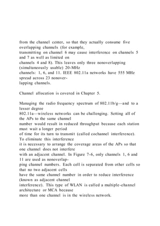
  • 1. from the channel center, so that they actually consume five overlapping channels (for example, transmitting on channel 6 may cause interference on channels 5 and 7 as well as limited on channels 4 and 8). This leaves only three nonoverlapping (simultaneously usable) 20-MHz channels: 1, 6, and 11. IEEE 802.11a networks have 555 MHz spread across 23 nonover- lapping channels. Channel allocation is covered in Chapter 5. Managing the radio frequency spectrum of 802.11b/g—and to a lesser degree 802.11a—wireless networks can be challenging. Setting all of the APs to the same channel number would result in reduced throughput because each station must wait a longer period of time for its turn to transmit (called cochannel interference). To eliminate this interference it is necessary to arrange the coverage areas of the APs so that one channel does not interfere with an adjacent channel. In Figure 7-6, only channels 1, 6 and 11 are used as nonoverlap- ping channel numbers. Each cell is separated from other cells so that no two adjacent cells have the same channel number in order to reduce interference (known as adjacent channel interference). This type of WLAN is called a multiple-channel architecture or MCA because more than one channel is in the wireless network.
  • 2. One of the keys to an MCA is to have the correct cell size in order to minimize adjacent channel interference. This is especially true when “scaling” or adding additional capacity to the WLAN. The most common approach, called the micro-cell architecture, creates small areas of coverage. Typically, in order to add wireless network capacity, more APs are added while the transmission power of all APs is reduced to minimize potential interference. This can usually provide acceptable network throughput if the site has been properly surveyed to identify the best locations for the APs. In addition, the configuration of BSSIDs and ESSIDs can be made easier in a micro-cell architecture. Single-Channel Architecture (SCA) The fundamental reason why multiple APs in a MCA are necessary is because the interference range of wireless devices exceeds their useful communication range. That is, devices that are too far apart to communicate can still be close enough to interfere with each other. An alter- native to MCA that addresses this weakness is the single- channel architecture (SCA). Instead of having each cell use a different channel as in WCA, WLANs using SCA have all of the APs use the same channel. Each AP has overlapping coverage that forms a continuous region on a single channel, thereby reducing interference. The SCA architecture is accomplished through 6 1 11 116 1 11 6 1 11 6 1
  • 3. 6 1 11 116 1 11 6 1 11 6 1 Figure 7-6 Nonoverlapping cells © Cengage Learning 2013 256 Chapter 7 WLAN Management and Architectures Copyright 2012 Cengage Learning. All Rights Reserved. May not be copied, scanned, or duplicated, in whole or in part. Due to electronic rights, some third party content may be suppressed from the eBook and/or eChapter(s). Editorial review has deemed that any suppressed content does not materially affect the overall learning experience. Cengage Learning reserves the right to remove additional content at any time if subsequent rights restrictions require it. 7 the use of lightweight APs and WLCs. Each lightweight AP broadcasts the same virtual BSSID (instead of multiple BSSIDs) and each has the same configured MAC address. This also serves to eliminate the cochannel interference problem. There are several advantages to SCA. The first advantage is smoother handoffs. A mobile sta- tion must receive an uninterrupted flow of frames when moving from the coverage area of one AP to another AP, especially when using VoIP. With MCA, the station responsible for this pro-
  • 4. cedure monitors the signal strength from multiple APs or data frame error rates. With SCA, the handoff is instead accomplished through coordination between the lightweight APs and the WLC. The stations cannot distinguish which AP is providing the coverage; instead, the net- work decides which AP should transmit and receive data for a particular station. This means that the stations are not involved in any handoff decision from one AP to another. As stations move, the network directs traffic to them via the nearest AP with available capacity. With SCA, the roaming clients are “fooled” into thinking that they are always interacting with the same AP when in reality they may be communicating with several different APs. A second advantage to SCA is that the often tedious planning process required for MCA WLANs is no longer needed. All APs are set to the same common RF channel and transmit power, eliminating the need for lengthy and often complex planning regarding the location and unique configuration of each AP. Another advantage to SCA is that because each AP is operating on the same channel, cochan- nel interference is no longer an issue. This can also improve the signal-to-noise ratio (SNR) that in turn increases throughput and reliability. A final advantage is that the SCA architecture provides more network information in order to make informed decisions. With MCA, a station and AP are
  • 5. essentially “in the dark” regarding the overall status of the network. Yet with SCA a more complete knowledge of the conditions at neighboring APs, and even historical information about how stations reacted previously when in similar situations, can be used when deciding which AP a roam- ing client should be associated with. MCA is similar to the centralized handover control of first- generation cellular telephone networks, while today’s 3G and 4G is based on a shared network-client responsibility like SCA. SCA can also support channel stacking. Channel stacking allows for increased capacity by hav- ing more than one SCA operating in an area. Instead of havi ng only one SCA on channel 1, another set of APs operating on channel 6 can also be added using a different BSSID. Stations can then associate with either SCA, thus dramatically increasing the available capacity. This additional capacity can be used for redundancy or to support higher data rates or user density. Instead of installing additional APs, channel stacking can also be accomplished by using APs that support multiple radios. Multiple-Channel Architecture vs. Single-Channel Architecture Models 257 Copyright 2012 Cengage Learning. All Rights Reserved. May not be copied, scanned, or duplicated, in whole or in part. Due to electronic rights, some third party content may be suppressed
  • 6. from the eBook and/or eChapter(s). Editorial review has deemed that any suppressed content does not materially affect the overall learning experience. Cengage Learning reserves the right to remove additional content at any time if subsequent rights restrictions require it. Wireless Network Management Systems (WNMS) C W N A 4.4.4. Define, describe, and implement a WNMS that manages autonomous APs, WLAN controllers, and mesh nodes. A wireless network management system (WNMS) is a set of hardware and/or software that can be used to provide unified management of a wireless network. This includes configuration man- agement, deployment, and especially troubleshooting. A WNMS can be used to isolate and solve wireless problems, which can have many different root causes (station wireless configuration errors, authentication problems, connectivity issues, problems with wired ports or switches, etc.). The typical features of a WNMS include: ● Configuration management. A new or updated configuration can be “pushed” out to all wireless devices, a single device, or a group of specific devices. These configurations can be designed so that general updates do not override specific configuration settings unique to each device.
  • 7. ● Firmware/Software distribution. As new firmware and software is made available, these can be distributed to all devices from a central management facility, with no need to “touch” each device. ● Intelligent scheduling. To minimize the impact of a new configuration or firmware update, many WNMS can be scheduled to automatically occur late at night or on the weekends when the wireless network usage is low. In addition, recurring tasks can be scheduled to automatically occur on a regular daily, weekly, or monthly basis. ● User and device monitoring. A WNMS can locate a specific user or device on a wire- less network often by WLAN administrator clicking a single button on a Web-based software interface. This allows a wireless technician to monitor historical information and use special diagnostic information to address problems. One of the disadvantages of a WNMS is that it cannot be used to monitor wireless network traffic as it occurs. Power Management C W N A 3.1.3. Explain and apply the power management features of WLANs. Most stations in a WLAN are portable laptop or tablet
  • 8. computers, giving the users the freedom to roam without being tethered to the network by wires. These devices depend upon batteries as their primary power source when they are mobile. To conserve battery power, 258 Chapter 7 WLAN Management and Architectures Copyright 2012 Cengage Learning. All Rights Reserved. May not be copied, scanned, or duplicated, in whole or in part. Due to electronic rights, some third party content may be suppressed from the eBook and/or eChapter(s). Editorial review has deemed that any suppressed content does not materially affect the overall learning experience. Cengage Learning reserves the right to remove additional content at any time if subsequent rights restrictions require it. 7 laptops are usually configured to go into a “sleep” mode after a specific period of time, when functions such as the hard drive or display screen are temporarily powered down by the computer. However, a laptop that is part of a WLAN must remain “awake” in order to receive wireless network transmissions. If a laptop is in sleep mode, it could miss important transmitted infor- mation or even lose the network connection altogether. The dilemma is how to allow the lap- top to power down into sleep mode during idle periods to preserve battery life yet continue to
  • 9. be active to receive network transmissions. The reason a wireless laptop must continue to remain awake to receive network transmissions is because the original IEEE 802 standard assumes that stations are always ready to receive a network message. The answer to the problem is known as power management. Power management allows a station to be in either active mode when it is continuously awake or in power save mode, which turns off the wireless network interface card adapter to conserve battery life but still not miss wireless transmissions. Power management is transparent to all protocols and appli- cations so that it will not interfere with normal network functions. Power save mode is also called continuous aware mode or constantly awake mode. IEEE 802.11 power management can be divided into two categories: basic power manage- ment and enhanced power management techniques. Basic Power Management In a BSS infrastructure WLAN, the steps of power save mode are as follows: 1. A station sends a frame to the AP with the Power Management field set to 1 to indicate that it will go into power save mode after this frame transmission.
  • 10. 2. The AP records that the station is in power save mode to prevent any frames from being sent to that station from the AP. 3. As the AP receives frames specifically for that station (unicast frames) it temporarily stores those frames at the AP (buffering). 4. At prescribed set times, the AP will send out a beacon frame to all stations. At the same time, all stations switch to active mode to receive the frame. This frame contains a list of the stations that have buffered unicast frames waiting at the AP. This list is known as the traffic indication map (TIM). 5. If a station learns from the TIM that buffered frames are waiting for it, that station will request the AP to have those frames forwarded (if it has no buffered frames then it can return to power save mode). Once the buffered frames are received the station can again return to power save mode. This is illustrated in Figure 7-7. Power Management 259 Copyright 2012 Cengage Learning. All Rights Reserved. May not be copied, scanned, or duplicated, in whole or in part. Due to electronic rights, some third party content may be suppressed from the eBook and/or eChapter(s). Editorial review has deemed that any suppressed content does not materially affect the overall learning experience. Cengage Learning reserves the right to remove additional content at any time if subsequent rights restrictions require it.
  • 11. The amount of power that a wireless network interface card adapter consumes is significant. One typical card requires 450 millionths of an amp (mA) to transmit and 270 mA to receive. While in power save mode it only consumes 15 mA. When a station in power save mode must receive a frame intended for all stations (multicast or broadcast frame) the AP will send a special TIM called a delivery traffic indication message (DTIM). All stations will then change to active mode to receive the frame. Power management for an IBSS is different because there is no AP. Every station in an IBSS must buffer the frames that it attempts to send to another device in case the receiving device is asleep. At a specific period of time, known as the ad hoc traffic indication message (ATIM) window, each station must be awake. At this time a station sends a beacon frame to all other stations. Those stations that previously attempted to send a frame to a sleeping station will now send an ATIM frame, which indicates that the receiving station has pending data to be received and must remain awake (any device that does not receive an ATIM frame can go back to sleep). Finally, the data frames are retrieved from the buffer and sent to the station that is now awake. There are a variety of configuration settings that can be used with
  • 12. power management. For example, different power save levels can be specified for a station in power save mode. One level may require that a station turn off the radio for as long as possible without losing network connectivity for the greatest power savings at the sake of network per- formance, while another setting can require that the station turn off the radio for small periods in order to provide optimal network performance. Enhanced Power Management Although the basic power management features can provide power savings, there are enhanced power management technologies that can provide additional functionality and Station A Power save mode Power save mode Active mode Station B Station C TIM Station A Yes
  • 13. Station C No Access point Send frames request Figure 7-7 Request for frames © Cengage Learning 2013 260 Chapter 7 WLAN Management and Architectures Copyright 2012 Cengage Learning. All Rights Reserved. May not be copied, scanned, or duplicated, in whole or in part. Due to electronic rights, some third party content may be suppressed from the eBook and/or eChapter(s). Editorial review has deemed that any suppressed content does not materially affect the overall learning experience. Cengage Learning reserves the right to remove additional content at any time if subsequent rights restrictions require it. 7 power savings. These include Unscheduled Automatic Power Save Delivery, Power Save Multi-Poll, and Spatial Multiplexing Power Save. Unscheduled Automatic Power Save Delivery (U-APSD) The Unscheduled Automatic Power Save Delivery (U-APSD), which is similar to the Wi-Fi Alliance’s WMM Power-Save (WMM-PS), is often used when a wireless station is
  • 14. using VoIP. With the basic power management settings a device using VoIP for a voice conversation may receive frames every 10–20 milliseconds (ms), while an AP usually sends out a beacon frame every 100 ms. Because the delay is too long, normally a station using VoIP simply could not afford to go into power save mode. With U-APSD, the station would inform the AP that it is operating according to this proto- col, and the AP will then save any frames destined for this station. However, instead of waiting for the AP to send a beacon frame to all stations as with basic power management, whenever the AP sees a frame coming from the station it will immediately release any frames it has been holding for the station. This allows the station to sleep until it needs to send a VoIP frame to the AP, and that frame also serves as an indicator to release any packets des- tined for it. Once the station has received its frames it then goes back into power save mode. There is a slight delay for the station in listen mode when using VoIP with U-APSD while the AP gathers up and sends the frames, at which time the station goes into receive mode. U-APSD improves the efficiency of the basic power management in two ways: it increases the amount of time that a station can be in power save mode and it decreases the number of frames that a station must send and receive in order to download stored frames on the AP. An interesting benefit of U-APSD is that, when higher data
  • 15. rates are used, overall power savings increase. This is because a station will spend less time actively transmitting and receiving and will spend more time in power save mode. A device using U-APSD for VoIP consumes approximately one- sixth of the power compared with not using U-APSD. Power Save Multi-Poll (PSMP) Another enhanced power management mechanism is the Power Save Multi-Poll (PSMP), which can have either a scheduled or an unscheduled component. Scheduled PSMP (S-PSMP) allows an AP to send a transmission schedule to one or more stations in a WLAN. This schedule informs the stations when they should be in active mode to receive frames as well as when they are allowed to begin transmitting. And since a station can only send or receive frames based on the schedule, other stations cannot interfere with the transmissions by attempting to send simultaneously. By using a schedule, stations can be in power save mode for the maximum amount of time without missing any frames. Unscheduled PSMP (U-PSMP) functionality does not replace U- APSD (WMM), but rather extends it to add further functionality. Power Management 261 Copyright 2012 Cengage Learning. All Rights Reserved. May not be copied, scanned, or duplicated, in whole or in part. Due to electronic rights, some third party content may be suppressed from the eBook and/or eChapter(s).
  • 16. Editorial review has deemed that any suppressed content does not materially affect the overall learning experience. Cengage Learning reserves the right to remove additional content at any time if subsequent rights restrictions require it. Although an improvement over basic power management, S- PSMP still requires a significant amount of overhead. In addition, stations may not be able to be in power save mode for extended periods of time. For example, with VoIP transmissions the time gap for station may be so short that the station must still remain in active mode while other stations are receiving their VoIP packets. Generally speaking, P-SPMP is used only if the number of sta- tions using VoIP associated with a single AP exceeds 15. If fewer than 15 stations are using VoIP, then U-APSD should be used instead. Spatial Multiplexing Power Save (SMPS) Spatial Multiplexing Power Save (SMPS) can be used with IEEE 802.11n devices using Multiple- Input Multiple-Output (MIMO). A device using MIMO may have a 2x3:2 configuration of two transmit antennas and three receive antennas (along with two data spatial streams), each having its own radio chain. Yet it is not necessary for all three of the receive radio chains to be simultaneously awake. This is because the station is only waiting to receive a low data rate beacon that may not be sent with MIMO encoding.
  • 17. SMPS allows the station to change from a 2x3:2 configuration to a 1x1:1 to save power. If the station is plugged into an electrical outlet running on alternating current (AC), it can be configured to run using all radio chains (since conserving power is not a concern). However, if the station begins running on a direct current (DC) battery, it will automatically “down- shift” to 1x1:1 while waiting to receive beacons. The station would then “upshift” back to 2x3:2 when necessary. SMPS is also called Dynamic MIMO Power Save. A device using SMPS can downshift and then tell the AP to prevent it from sending any MIMO-encoded frames to the device with only one receive radio chain. The AP can then send a request to send (RTS) packet that indicates the AP is about to send a MIMO packet so that the device can upshift to receive it. The power savings provided by SMPS can be significant. The ability to dynamically change the MIMO configuration can reduce power consumption by 30 percent when the traffic is low. Chapter Summary ■ The most common type of wireless architecture is an autonomous access point archi- tecture. Each AP is independent or autonomous from all other APs. There are several enhanced features in this type of architecture. Two of the most advanced features are
  • 18. Quality of Service (QoS) and wireless virtual LANs (VLANs). QoS provides the ability to prioritize different types of frames so that those frames that are more time-dependent, such as voice and video, can be given a higher priority (and arrive earlier) than standard data frames. A wireless VLAN is often used to segment traffic. Wireless 262 Chapter 7 WLAN Management and Architectures Copyright 2012 Cengage Learning. All Rights Reserved. May not be copied, scanned, or duplicated, in whole or in part. Due to electronic rights, some third party content may be suppressed from the eBook and/or eChapter(s). Editorial review has deemed that any suppressed content does not materially affect the overall learning experience. Cengage Learning reserves the right to remove additional content at any time if subsequent rights restrictions require it. 7 VLANs can be configured in one of two ways. The difference depends upon which device separates the packets and directs them to different networks. ■ A controller-based architecture uses a wireless LAN controller (WLC) to manage and provide configuration services to the WLAN. Access points in a controller-based architecture are significantly different. A lightweight access point does not contain the
  • 19. management and configuration functions that are found in autonomous access points; instead, these features are contained in the centralized WLC. Lightweight access points only have simplified radios for wireless communication between devices and a media converter for accessing the wired network. A lightweight mesh AP can be used instead of a standard mesh AP. Lightweight mesh APs can also be centrally configured and managed through a WLC. A captive portal AP uses a standard Web browser to pro- vide information, give the wireless user the opportunity to agree to a policy, or present valid login credentials. The WLC is a device that can be centrally configured; these settings are then automatically distributed to all lightweight access points. ■ Besides autonomous access point architectures and control - based architectures, there are other types of WLANs. A WLAN array is a proprietary product that resembles a round consumer-grade smoke detector and replaces a standard WLC installed in a rack in a server closet. The WLAN array contains a WLC that can be directly con- nected to as many as 16 integrated access points. Cooperative control is another proprietary technology marketed architecture that enables APs to communicate and coordinate with each other without the need for a WLC, so that each AP contains the capabilities of a WLC. Wireless mesh access points communicate wirelessly with the next closest mesh access point.
  • 20. ■ A multiple-channel architecture, or MCA, has more than one channel in the wireless network. Each cell is separated from other cells so that no two adjacent cells have the same channel number in order to reduce interference. An alternative to MCA is the single-channel architecture (SCA). Instead of having each cell use a different channel as in WCA, WLANs using SCA have all of the APs use the same channel. Each AP has overlapping coverage that forms a continuous region on a single channel, thereby reducing interference. The SCA architecture is accomplished through the use of lightweight APs and WLCs. ■ A wireless network management system (WNMS) is a set of hardware and/or software that can be used to provide unified management of a wireless network. This includes configuration management, deployment, and especially troubleshooting. A WNMS can be used to isolate and solve wireless problems, which can have many different root causes (station wireless configuration errors, authentication problems, connectivity issues, problems with wired ports or switches, etc.). ■ Power management allows a station to be in either active mode (continuously awake) or in power save mode (turns off the wireless network interface card adapter to con- serve battery life but still not miss wireless transmissions). Power management is transparent to all protocols and applications so that it will not
  • 21. interfere with normal network functions. Basic power management involves the AP temporarily storing frames and then releasing them to the stations. Although the basic power management features can provide power savings, there are enhanced power management technolo- gies that can provide additional functionality and power savings. With Unscheduled Automatic Power Save Delivery (U-APSD) a station informs the AP that it is operating Chapter Summary 263 Copyright 2012 Cengage Learning. All Rights Reserved. May not be copied, scanned, or duplicated, in whole or in part. Due to electronic rights, some third party content may be suppressed from the eBook and/or eChapter(s). Editorial review has deemed that any suppressed content does not materially affect the overall learning experience. Cengage Learning reserves the right to remove additional content at any time if subsequent rights restrictions require it. according to this protocol, and the AP will then save any frames destined for this station. Whenever the AP sees a frame coming from the station, it will immediately release any frames it has been holding for the station. Power Save Multi-Poll (PSMP) allows an AP to send a transmission schedule to one or more stations in a WLAN. This schedule informs the stations when they should be in active mode to receive
  • 22. frames as well as when they are allowed to begin transmitting. Spatial Multiplexing Power Save (SMPS) allows a station to change from a MIMO configuration to a single radio in order to conserve power. Key Terms active mode A power management state in which the station is continuously awake. ad hoc traffic indication message (ATIM) window A specific period of time that each station must be awake. adjacent channel interference Each cell is separated from other cells so that no two adjacent cells have the same channel number in order to reduce interference. captive portal AP An AP that uses a standard Web browser to provide information, give the wireless user the opportunity to agree to a policy, or present valid login credentials. channel stacking A technology that allows for increased capacity by having more than one SCA operating in an area. cloud management Connecting wireless devices together using the Internet in order to remotely manage them. cochannel interference Reduced throughput caused as a result of all of APs set to the same channel number. cooperative control A proprietary product in which each AP contains the capabilities of a WLC. delivery traffic indication message (DTIM) A special TIM sent by an AP that is used when a station in power save mode must receive a frame intended for all stations.
  • 23. distributed WLAN architecture A wireless architecture configuration in which multiple APs form a non-centralized network through a wireless connection. IEEE 802.11e-2005 The IEEE QoS standards. IEEE 802.1q An IEEE standard for marking VLAN packets. lightweight mesh AP A mesh AP that is centrally configured and managed through a WLC. micro-cell architecture A wireless architecture that creates small areas of coverage. multiple-channel architecture (MCA) A wireless architecture in which more than one channel is used in the wireless network. power management A technology that allows a WLAN to conserve power. power save mode A power management state in which the station turns off the wireless network interface card adapter to conserve battery life. Power Save Multi-Poll (PSMP) An enhanced power management technology that can have either a scheduled or an unscheduled component. Quality of Service (QoS) Prioritizing different types of frames over a network. 264 Chapter 7 WLAN Management and Architectures Copyright 2012 Cengage Learning. All Rights Reserved. May not be copied, scanned, or duplicated, in whole or in part. Due to electronic rights, some third party content may be suppressed from the eBook and/or eChapter(s). Editorial review has deemed that any suppressed content does not materially affect the overall learning experience. Cengage Learning reserves the right to remove additional content at any time if subsequent rights restrictions require it.
  • 24. 7 Scheduled PSMP (S-PSMP) An enhanced power management technology in which the AP sends a transmission schedule to one or more stations in a WLAN. single-channel architecture (SCA) An architecture in which all of the APs use the same channel. SNMP (Simple Network Management Protocol) A management protocol that provides information such as the number of bytes transmitted and received, the number of frames transmitted and received, the number of errors, and port status. Spatial Multiplexing Power Save (SMPS) An enhanced power management technology that turns off MIMO radios. split MAC A division in which lightweight APs only handle the real-time layer functions while MAC functionality is processed by the WLC. total cost of ownership (TCO) The total cost of owning a product, including acquisition, setup, support, ongoing maintenance, service, and all operating expenses. traffic indication map (TIM) A list of stations that have buffered unicast frames waiting at the AP. trunking A single cable is used to support multiple virtual LANs. Unscheduled Automatic Power Save Delivery (U-APSD) A technology in which whenever the AP sees a frame coming from the station it will immedi ately releases any frames it has
  • 25. been holding for the station. virtual local area network (VLAN) A logical grouping of network devices within a larger physical network. Voice over IP (VoIP) A telephony system that uses Internet Protocol (IP-based) data packet switching networks to transmit voice communications. Wi-Fi Multimedia (WMM) A QoS specification created in 2004 by the Wi-Fi Alliance modeled after a wired network QoS prioritization scheme. wireless network management system (WNMS) A set of hardware and/or software that can be used to provide unified management of a wireless network. wireless switch Another name for a WLAN controller. wireless VLANs A wireless virtual LAN typically used to segment traffic. WLAN array A proprietary product marketed that contains a WLC that can be directly connected to as many as 16 integrated APs. WLAN profile A set of specific configurations that can be applied to different wireless stations. WMM Power-Save (WMM-PS) A technology that is similar to Unscheduled Automatic Power Save Delivery (U-APSD). Review Questions 1. In an autonomous access point the “intelligence” for wireless management, authentica- tion, and encryption is contained in which device? a. wireless network interface card adapter b. WLC
  • 26. c. station d. access point Review Questions 265 Copyright 2012 Cengage Learning. All Rights Reserved. May not be copied, scanned, or duplicated, in whole or in part. Due to electronic rights, some third party content may be suppressed from the eBook and/or eChapter(s). Editorial review has deemed that any suppressed content does not materially affect the overall learning experience. Cengage Learning reserves the right to remove additional content at any time if subsequent rights restrictions require it. 2. Each of the following is a feature found in an autonomous access point except: a. support for Wireless Distribution Systems (WDS). b. quality of service. c. adjustable transmit power. d. WLC. 3. The capability to prioritize different types of frames is known as . a. VoIP b. Quality of Service (QoS)
  • 27. c. Wi-Fi Prioritization (WFP) d. IEEE 802.15f 4. The most flexible approach for separating packets and directing them to different networks in a wireless VLAN is to use the network . a. access point (AP) b. switch c. hub d. router 5. What is a split MAC architecture? a. A lightweight AP that handles only the real-time MAC layer functions in itself while all other functions are processed by the WLC b. A WLC that has two MAC addresses c. A VoIP WLAN that uses a different MAC for each station d. A wireless network interface card adapter that can change its MAC address 6. Each of the following can be used by a captive portal AP except: a. advertisement. b. encryption.
  • 28. c. general authentication. d. agree to an Acceptable Use Policy. 7. Which of the following is not a recognized functional area of a network? a. core layer b. distribution layer c. station layer d. access layer 8. A is a set of specific configurations that can be applied to different wireless stations. a. WLAN profile b. management configuration 266 Chapter 7 WLAN Management and Architectures Copyright 2012 Cengage Learning. All Rights Reserved. May not be copied, scanned, or duplicated, in whole or in part. Due to electronic rights, some third party content may be suppressed from the eBook and/or eChapter(s). Editorial review has deemed that any suppressed content does not materially affect the overall learning experience. Cengage Learning reserves the right to remove additional content at any time if subsequent rights restrictions require it.
  • 29. 7 c. WLC frame d. data resource package (DRP) 9. A WLAN array . a. is only a prototype and has not yet been developed for actual use b. can only be used on a mesh network c. uses multiple HiveAPs to share load balancing d. contains a WLC that can be directly connected to as many as 16 integrated access points 10. Which is not true regarding a multiple-channel architecture configuration? a. Cochannel interference can be a significant problem. b. With IEEE 802.11b/g there are only three nonoverlapping channels. c. Each cell must be separated from other cells so that no two adjacent cells have the same channel number. d. WLCs cannot be used in a multiple-channel architecture. 11. A WLAN that uses a single-channel architecture has each AP .
  • 30. a. using the same channel number b. in a mesh network c. in a closed array configuration d. using higher power levels to send the signal farther 12. Channel stacking . a. can only be used with MCA b. is restricted to WLAN array configurations c. uses more than one SCA in an area d. is illegal in the United States 13. A set of hardware and/or software that can be used to provide unified management of a wireless network is called a . a. configuration manager b. Unified Software System c. Wireless LAN Controller (WLC) d. wireless network management system (WNMS) 14. Which of the following is not a step of the power save mode in basic power manage- ment in a BSS? a. A station sends a frame to the AP with the Power
  • 31. Management field set to 1 to indicate that it will go into power save mode after this frame transmission. b. The user must manually put the wireless network card interface adapter into power save mode. Review Questions 267 Copyright 2012 Cengage Learning. All Rights Reserved. May not be copied, scanned, or duplicated, in whole or in part. Due to electronic rights, some third party content may be suppressed from the eBook and/or eChapter(s). Editorial review has deemed that any suppressed content does not materially affect the overall learning experience. Cengage Learning reserves the right to remove additional content at any time if subsequent rights restrictions require it. c. As the AP receives frames specifically for that station it temporarily stores those frames at the AP. d. At prescribed set times the AP will send out a beacon frame to all stations. 15. What is a traffic indication map (TIM)? a. a list of the stations that have buffered unicast frames waiting at the AP b. the route that frames take when transmitted from the AP to a station
  • 32. c. the congestion that results from too many stations in a micro cell d. a grid on a mesh network that lists all of the WLCs 16. Which of the following is not a characteristic of the Unscheduled Automatic Power Save Delivery (U-APSD)? a. It is similar to Wi-Fi Alliance’s WMM Power-Save (WMM- PS). b. It cannot be used with VoIP. c. Stations inform the AP that it is operating according to this protocol. d. Whenever the AP sees a frame coming from the station it will immediately release any frames it has been holding for the station. 17. Power Save Multi-Poll (PSMP) sends a(n) from the AP to the stations. a. schedule b. arbitration frame c. automated alert d. Point Coordination Function IFS 18. Spatial Multiplexing Power Save (SMPS) can only be used with which devices?
  • 33. a. VoIP b. WLC c. IEEE 802.11a d. IEEE 802.11n 19. With Distributed Coordination Function (DCF) . a. each wireless station has the same opportunity as all other stations for accessing the medium b. all stations register with the AP their unique TDIM c. data transmissions have a higher priority than voice frames d. QoS is unnecessary 20. The IEEE QoS standard for WLANs is known as . a. Background Scheduling b. QoS Scheduling Configuration (QSC) c. WMM Background Priority d. IEEE 802.11e-2005 268 Chapter 7 WLAN Management and Architectures Copyright 2012 Cengage Learning. All Rights Reserved. May not be copied, scanned, or duplicated, in whole or in part. Due to electronic rights, some third party content may be suppressed from the eBook and/or eChapter(s).
  • 34. Editorial review has deemed that any suppressed content does not materially affect the overall learning experience. Cengage Learning reserves the right to remove additional content at any time if subsequent rights restrictions require it. 7 Hands-On Projects Project 7-1: Configuring Access Points—Advanced Settings The ability to properly configure an access point is an important skill for any wireless network professional as well as, to a lesser degree, for end-users. In this project you will use an online emulator from D-Link to configure an autonomous access point’s advanced settings. 1. Use your Web browser to go to www.dlink.com. It is not unusual for Web sites to change the location of where files are stored. If the URL above no longer functions then open a search engine and search for “D-Link emulator”. 2. Click the nation most appropriate for you. 3. Click Support. 4. Click Go next to Emulators.
  • 35. 5. Scroll down and click DAP-1522. 6. Click DAP-1522 AP Mode. 7. The emulated login screen appears. Click Login. 8. An emulated Setup screen displaying what a user would see when configuring an actual DAP-1522 is displayed, as shown in Figure 7-8. 9. Click Advanced on the horizontal menu bar. 10. Click Advanced Wireless in the left pane to display the Advanced Wireless screen. 11. Click the down arrow next to Transmit Power. Click the down arrow again to close the drop-down list without making any changes. Why would you want to reduce the power of the AP? Click the down arrow again to close the drop-down list without making any changes. 12. Notice that, by default, the Beacon Period is set to 100 msec. What would happen if you decreased that value? What would happen if you increased it? 13. WMM Enable is selected by default. Wi-Fi Multimedia (WMM) is modeled after a wired network QoS prioritization scheme and outlines four levels of prioritization for WLAN QoS. Should this be on by default? What impact would it have on the WLAN?
  • 36. 14. The Short GI is also on by default. In the right pane, under Help, click More and read about the settings for this model under Advanced Wireless. If you were using this device, would you use Short GI? Why or why not? 15. Keep the emulator open in your browser for the next project. Hands-On Projects 269 Copyright 2012 Cengage Learning. All Rights Reserved. May not be copied, scanned, or duplicated, in whole or in part. Due to electronic rights, some third party content may be suppressed from the eBook and/or eChapter(s). Editorial review has deemed that any suppressed content does not materially affect the overall learning experience. Cengage Learning reserves the right to remove additional content at any time if subsequent rights restrictions require it. Project 7-2: Configuring Access Points—QoS In this project you will use the online emulator from D-Link to configure an autonomous access point’s QoS settings. 1. If necessary navigate to the DAP-1522 Advanced Wireless screen. 2. Click QOS in the left pane to display the QOS menu as shown in Figure 7-9. 3. In the right pane, under Help, click More and read about the settings for this model
  • 37. under QOS. 4. Click your browser’s Back button to return to the QOS screen. 5. Under QOS click the Enable Qos box to insert a check. 6. Now create a QoS rule. Under ADD QOS RULE, click the Enable Qos box to insert a check. 7. In the Name box type WebTraffic. This will set a rule for HTTP Web traffic to be at the lowest priority. 8. Verify that the Priority is set to Background(BK). Background has the lowest level of priority. Figure 7-8 DAP-1522 Emulated Setup screen © Cengage Learning 2013 270 Chapter 7 WLAN Management and Architectures Copyright 2012 Cengage Learning. All Rights Reserved. May not be copied, scanned, or duplicated, in whole or in part. Due to electronic rights, some third party content may be suppressed from the eBook and/or eChapter(s). Editorial review has deemed that any suppressed content does not materially affect the overall learning experience. Cengage Learning reserves the right to remove additional content at any time if subsequent rights restrictions require it.
  • 38. 7 9. In the Protocol box select TCP. 10. For the Host 1 IP Range, type the range 192.168.1.1 in the first box and 192.168.1.101 in the second box. This part of the rule will apply to traffic that is received by any device in the local network that has an IP address within this range. 11. For the Host 1 Port Range, enter 80 in the first box and 80 in the second box. This part of the rule will apply to traffic in which Host 1’s port number is within this range (HTTP traffic). 12. For the Host 2 IP Range, enter the range 0.0.0.0 in the first box and 255.255.255.255 in the second box. This sets the rule to apply to traffic that is sent by any device that has an IP address within this range (any computer). 13. For the Host 2 Port Range, enter 0 in the first box and 65535 in the second box. This rule applies to traffic in which Host 2’s port number is within this range (all protocols). 14. Click Clear. 15. Now create the settings that give the highest priority to FTP traffic for computers on the local network. 16. Close all windows.
  • 39. Figure 7-9 DAP-1522 QoS screen © Cengage Learning 2013 Hands-On Projects 271 Copyright 2012 Cengage Learning. All Rights Reserved. May not be copied, scanned, or duplicated, in whole or in part. Due to electronic rights, some third party content may be suppressed from the eBook and/or eChapter(s). Editorial review has deemed that any suppressed content does not materially affect the overall learning experience. Cengage Learning reserves the right to remove additional content at any time if subsequent rights restrictions require it. Project 7-3: Configuring Access Points—Performance In this project you will use the online emulator from D-Link to configure an autonomous access point’s performance settings. 1. Use your Web browser to go to www.dlink.com. It is not unusual for Web sites to change the location of where files are stored. If the URL above no longer functions then open a search engine and search for “D-Link emulator”. 2. Click the nation most appropriate for you. 3. Click Support. 4. Click Go next to Emulators.
  • 40. 5. Scroll down and click DAP-3520 6. The emulated login screen appears. Click Login. 7. An emulated Home screen displaying what a user would see when configuring an actual DAP-3520. 8. In the left pane, expand all of the options so that they are displayed as shown in Figure 7-10. 9. In the left pane, under Basic Settings, click Wireless. 10. Click the down arrow next to Wireless Band. What are the two types of IEEE 802.11 networks that are available for the first band? What are available for the second band? Click the down arrow again to close the drop-down menu without making any changes. 11. Click the down arrow next to Mode. When would the device be configured as a Wire- less Distribution System (WDS)? When would it be used as a WDS with AP? Click the down arrow again to close the drop-down menu without making any changes. 12. Change the Wireless Band from 2.4GHz to 5GHz. Notice how the Channel also changes. Why does it change? 13. Change the Wireless Band back to 2.4GHz.
  • 41. 14. In the left pane under Advanced Settings click Performance. 15. Change the Wireless Mode setting to Mixed 802.11g and 802.11b. 16. Click the down arrow next to Data Rate. What options are available? Click the down arrow again to close the drop-down menu without making any changes. 17. Change the Wireless Mode setting to Mixed 802.11n, 802.11g and 802.11b. 18. What is the only Data Rate option that appears for this mode? 19. Click the arrow next to Transmit Power. Why is the default set to the lowest value? Click the down arrow again to close the drop-down menu without making any changes. 20. Change the Wireless Mode setting to Mixed 802.11g and 802.11b. Why does the Short GI become disabled with this option? 21. Keep the emulator open for the next project. 272 Chapter 7 WLAN Management and Architectures Copyright 2012 Cengage Learning. All Rights Reserved. May not be copied, scanned, or duplicated, in whole or in part. Due to electronic rights, some third party content may be suppressed from the eBook and/or eChapter(s). Editorial review has deemed that any suppressed content does not materially affect the overall learning experience. Cengage
  • 42. Learning reserves the right to remove additional content at any time if subsequent rights restrictions require it. 7 Project 7-4: Configuring Access Points—VLAN In this project you will use an online emulator from D-Link to configure an autonomous access point’s VLAN settings. 1. If necessary, navigate to the DAP-3520 Home screen. 2. In the left pane, click Multi-SSID under Advanced Settings to display the Multi-SSID settings as shown in Figure 7-11. 3. Check the Enable Multi-SSID box to insert a check. When would this option be used? 4. Click the Enable Priority box to insert a check. 5. In the left screen, click VLAN under Advanced Settings to display the used VLAN Settings screen. 6. Next to VLAN Status click Enable. 7. Click the Add/Edit VLAN tab. 8. Next to VLAN ID (VID) enter VLAN1. Figure 7-10 DAP-3520 Emulated Home screen © Cengage Learning 2013
  • 43. Hands-On Projects 273 Copyright 2012 Cengage Learning. All Rights Reserved. May not be copied, scanned, or duplicated, in whole or in part. Due to electronic rights, some third party content may be suppressed from the eBook and/or eChapter(s). Editorial review has deemed that any suppressed content does not materially affect the overall learning experience. Cengage Learning reserves the right to remove additional content at any time if subsequent rights restrictions require it. 9. Next to VLAN Name enter Accounting. 10. In the Port section next to Untag note that the Mgmt option is selected. What would this option do? 11. In the Port section next to Tag, check the LAN option. What would this do? 12. Close all windows. Case Projects Case Project 7-1: WMM Devices Wi-Fi Multimedia (WMM) technology can now be found in televisions, cam- eras, and other devices to create a wireless infrastructure for home entertain- ment networks. Use the Internet to research WMM technology in these devices. Write a one-page paper on your findings.
  • 44. Figure 7-11 DAP-3520 Emulated Multi-SSID Settings screen © Cengage Learning 2013 274 Chapter 7 WLAN Management and Architectures Copyright 2012 Cengage Learning. All Rights Reserved. May not be copied, scanned, or duplicated, in whole or in part. Due to electronic rights, some third party content may be suppressed from the eBook and/or eChapter(s). Editorial review has deemed that any suppressed content does not materially affect the overall learning experience. Cengage Learning reserves the right to remove additional content at any time if subsequent rights restrictions require it. 7 Case Project 7-2: HCCA HCF Controlled Channel Access (HCCA) uses polling along with centralized scheduling controlled by the AP. Use the Internet to research HCCA. How does it function? What are its strengths and limitations? Why is it preferable over other forms of QoS? Write a one-page paper about your research. Case Project 7-3: Captive Portal APs Captive Portal APs are very commonly found in a variety of settings. Use the Internet to research Captive Portal APs. How are they typically used? What are their security vulnerabil- ities? What open source products are available? Write a one-
  • 45. page paper on your research. Case Project 7-4: Proprietary Products Both WLAN arrays and cooperative control are proprietary products from Xirrus and Aero- hive. Access the Web sites of these companies and research these two products. In what applications are they found? How are they being used? What advantages are advertised for them? Write a paper on the information that you find. Case Project 7-5: Nautilus IT Consulting Nautilus IT Consulting (NITC), a computer technology business, needs your assistance with one of their new clients. Dawn’s Art and Interiors (DAI) operates several galleries across the state and wants to upgrade their WLAN. They have recently migrated to VoIP and they want to extend this functionality to their wireless network. DAI needs help determining which QoS option is best for them. 1. Create a PowerPoint presentation of eight or more slides that compares the different types of QoS, discussing their respective strengths and weaknesses. This presentation should contain technical information for the IT staff. 2. After your presentation DAI wants your opinion. Write a one- page memo that presents your choice and explains why they should explore this option. Case Projects 275
  • 46. Copyright 2012 Cengage Learning. All Rights Reserved. May not be copied, scanned, or duplicated, in whole or in part. Due to electronic rights, some third party content may be suppressed from the eBook and/or eChapter(s). Editorial review has deemed that any suppressed content does not materially affect the overall learning experience. Cengage Learning reserves the right to remove additional content at any time if subsequent rights restrictions require it. Copyright 2012 Cengage Learning. All Rights Reserved. May not be copied, scanned, or duplicated, in whole or in part. Due to electronic rights, some third party content may be suppressed from the eBook and/or eChapter(s). Editorial review has deemed that any suppressed content does not materially affect the overall learning experience. Cengage Learning reserves the right to remove additional content at any time if subsequent rights restrictions require it. chapter8 Conducting a Site Survey After completing this chapter you should be able to: • Explain what a site survey is and how it can be used • List and describe the tools used for conducting a site survey • Describe the procedures for performing a site survey 277 Copyright 2012 Cengage Learning. All Rights Reserved. May
  • 47. not be copied, scanned, or duplicated, in whole or in part. Due to electronic rights, some third party content may be suppressed from the eBook and/or eChapter(s). Editorial review has deemed that any suppressed content does not materially affect the overall learning experience. Cengage Learning reserves the right to remove additional content at any time if subsequent rights restrictions require it. A key link in the chain of putting products into the hands of consumers is a distribu- tion center (DC). DCs receive tens of thousands of different products from suppliers all across the world each hour. The job of the DC is to store these items and then as needed select the correct items and quantities to ship to retail stores or directly to consumers. Most DCs have miles of conveyor belts that snake their way through the building past racks holding the products. Workers who are stationed in specific areas walk over and pick the required items off these racks and place them on the con- veyor (called “pick and pass”). The items make their way to “sortation” areas, where all of the items for a shipment are consolidated together and loaded onto a truck. DCs are very labor-intensive operations, with many workers making multiple touches of each and every product. Yet instead of having workers wait by a moving conveyor belt to pick and pass products, what if the products came directly to the workers?
  • 48. That’s the idea behind a new type of DC system developed by Kiva Systems (which was purchased by Amazon in 2012). Mobile robotic drive units bring inventory pods directly to the workers who then select the items needed for the order. A single worker can complete an entire order—even consisting of hundreds of products—without having to move. When a pallet of items from a supplier enters the DC, instead of being moved by a forklift to be stored on a rack, it is instead placed onto a pod base. The pod base (along with the pallet) is then moved by the robots, which have been called “fast- moving orange tortoises.” When an order comes in for that product, the robots bring the entire pallet to a stationary worker at a packing station, where the items are selected, packed into boxes, and loaded onto trucks. The use of these intelligent robots makes it possible to build more flexibility into the process. For example, the sequence of the robots can be controlled so that heavier items arrive first (to be placed at the bottom of the shipping box) before lighter items arrive. In addition, items that are more popular (such as Christmas ornaments in December) can be located closer to packing stations to reduce the time needed to reach the station. The robotic drive units navigate by reading removable optical markers that form a grid pattern on the DC’s floor, so it is not necessary to bury
  • 49. wires in the floor’s con- crete. The drive units are battery powered and can operate for up to eight hours on a single charge. (When the batteries begin to run low, the drive unit automatically goes to a charging station on the floor and plugs itself in.) Controlling software deci- des which order goes to which operator, which drive unit retrieves which pod, and which path a drive unit should take to reach the packing station. Because the drive units are portable, the software communicates with them using wireless local area network technology, which can also interface with any existing WLAN in the DC. Real World Wireless 278 Chapter 8 Conducting a Site Survey Copyright 2012 Cengage Learning. All Rights Reserved. May not be copied, scanned, or duplicated, in whole or in part. Due to electronic rights, some third party content may be suppressed from the eBook and/or eChapter(s). Editorial review has deemed that any suppressed content does not materially affect the overall learning experience. Cengage Learning reserves the right to remove additional content at any time if subsequent rights restrictions require it. 8 One of the unique challenges of setting up a wireless LAN (WLAN) is determining the opti-
  • 50. mum location for the access points (APs) and other wireless devices. Because obstacles such as walls, floors, elevator shafts, and even people can impact the radio frequency (RF) signal, it is important to take these factors into consideration prior to installing equipment. In addi- tion, as conditions continue to change—new office walls are installed or old walls removed, more wireless users are added to the network, competing wireless networks are installed in neighboring offices—it is important to monitor and adjust the WLAN to keep it operating at peak efficiency. This involves using a variety of specific tools and established procedures. In this chapter you explore the necessary steps for locating wireless equipment by performing a site survey. First you learn what a site survey is and about the different types of surveys. Next, you explore the tools that are used to conduct the survey. Finally, you look at how to gather the necessary data and conduct a survey. What Is a Site Survey? C W N A 6.2.1 Identify the equipment, applications, and system features involved in performing predictive site surveys. 6.2.3 Identify the equipment, applications, and methodologies involved in self-managing RF technologies. Most users, when installing a WLAN in a home or apartment, generally do not give much time to determining the optimum location for the wireless router
  • 51. so that its RF signal coverage is uniform throughout the house but extends outside it as little as possible. Instead, these devices are typically placed wherever it is convenient, such as next to the Internet connection, near a desktop computer, or even tucked away on a bookcase that happens to have enough space to accommodate it. If the wireless signal happens not to reach into the far corners of the house or outside onto an outdoors deck, then those areas are simply recognized as being “dead space” and are just avoided when using the network. However, when installing a WLAN for an organization, areas of dead space may not be so easily tolerated. Whereas at home a user may simply move to another room, that may not always be possible in a building with multiple offices, locked doors, and private cubicles. This means important considerations must be taken into account when installing a new WLAN for an organization: all areas of a building should have adequate wireless coverage, all employees must have a reasonable amount of bandwidth, and, for security reasons, The technology provided by Kiva Systems is not cheap. The least expensive system costs $1 million for 30 robots and two packing stations, while systems for large DCs usually cost between $4 million to $6 million. (Soon it will be possible to lease Kiva Systems technology for high-peak seasonal times.) Yet with worker efficiency increased by up to 400 percent, Kiva’s wireless devices may become the wave of the
  • 52. future. What Is a Site Survey? 279 Copyright 2012 Cengage Learning. All Rights Reserved. May not be copied, scanned, or duplicated, in whole or in part. Due to electronic rights, some third party content may be suppressed from the eBook and/or eChapter(s). Editorial review has deemed that any suppressed content does not materially affect the overall learning experience. Cengage Learning reserves the right to remove additional content at any time if subsequent rights restrictions require it. a minimum amount of wireless signal should “bleed” outside the walls of the building. A vari- ety of factors can impact these goals, such as: ● Are there machines and electronic devices—such as cordless phones, lighting, satellite dishes, or microwave ovens—emitting radio waves that could interfere with or even block the WLAN signals? ● Will the wireless network be in an open environment with few walls or structures to block the signal, or will the network be installed in a warehouse or office that is filled with steel beams, concrete pillars, large filing cabinets, and heavy machinery that could reduce the range of the signal? ● Are office and conference room doors frequently closed or do they remain open?
  • 53. ● Will machinery be periodically moved to different locations? ● Are partitions moved frequently? ● Is the company expanding its physical plant or adding more employees that might impact wireless transmissions? ● Is there any potential interference from existing internal WLANs? ● Could there be interference from wireless signals from outside the organization, such as from a nearby building? Assuring that a WLAN can provide its intended functionality and meet its required design goals can best be achieved through a site survey. A site survey is an in-depth examination and analysis of a WLAN site. There are several reasons for conducting a site survey, just as there are different types of surveys. Purpose of a Site Survey A site survey is more than determining the location for a new AP. Instead, site surveys have several different design goals: ● Achieve the best possible performance from the WLAN ● Certify that the installation will operate as promised ● Determine the best location for APs ● Develop networks optimized for a variety of applications ● Ensure that the coverage will fulfill the organization’s requirements ● Locate any unauthorized APs on the network ● Map any nearby wireless networks to determine existing radio interference ● Reduce radio interference as much as possible
  • 54. ● Make the wireless network secure Often the success or failure of a wireless network can be directly linked to the thoroughness of the site survey. 280 Chapter 8 Conducting a Site Survey Copyright 2012 Cengage Learning. All Rights Reserved. May not be copied, scanned, or duplicated, in whole or in part. Due to electronic rights, some third party content may be suppressed from the eBook and/or eChapter(s). Editorial review has deemed that any suppressed content does not materially affect the overall learning experience. Cengage Learning reserves the right to remove additional content at any time if subsequent rights restrictions require it. 8 A site survey provides a realistic understanding of the infrastructure required for the installation of a new wireless network. It also assists in predicting network capability and throughput, as well as indicating the exact location of APs and power levels required. Where applicable, interference from existing devices or neighboring sites is also addressed during the site survey. Conducting a site survey is both an art and a science. Some of the steps in a site survey involve taking detailed measurements, but other steps can require a combination of experience and trial
  • 55. and error to achieve optimal results. When to Perform a Site Survey Although a site survey should be performed prior to installing a WLAN, a site survey is important other times, too. This is because a variety of factor s can change the performance of the wireless network, and these factors may not have been in existence or may have signif- icantly changed since the original survey. These factors include: ● Physical changes to a building. Remodeling can introduce new sources of interference within the coverage area of the AP, such as motors or metal structures. ● Changes to an existing wireless network. When modifying or extending an existing network structure, it is important to reevaluate the placement of the APs and antennas. ● Changes in network needs. If employees are performing significantly different duties, such as downloading large files on a regular basis, then a new site survey should be performed. ● Significant changes in personnel. Adding several new employees to an office or moving employees from one area to another area may necessitate a new site survey. Site surveys fall into four different categories, based on when they are conducted. These are summarized in Table 8-1.
  • 56. Site Survey Category Description Predeployment Site Surveys Prior to installing one or more APs, a predeployment survey should be conducted. The purpose of this survey is to understand the RF signal behavior in the specific environment. Postdeployment Site Surveys After the WLAN is installed, it is important to thoroughly test the setup to ensure that all of the APs are providing the necessary coverage. Periodic Site Surveys This “health check” site survey is generally not as thorough as a postdeployment survey. Instead, the purpose is simply to check that the WLAN is functioning as expected from the perspective of a client device. Troubleshooting Site Surveys When the WLAN is not functioning as anticipated a troubleshooting site survey can help to identify the reason for the inadequate performance. Table 8-1 Categories of Site Surveys © Cengage Learning 2013 What Is a Site Survey? 281 Copyright 2012 Cengage Learning. All Rights Reserved. May not be copied, scanned, or duplicated, in whole or in part. Due to electronic rights, some third party content may be suppressed
  • 57. from the eBook and/or eChapter(s). Editorial review has deemed that any suppressed content does not materially affect the overall learning experience. Cengage Learning reserves the right to remove additional content at any time if subsequent rights restrictions require it. Many organizations perform a periodic site survey regularly once each quarter. One of the primary factors dictating the need for site surveys is the ever-changing environ- ment in which the RF signal must be transmitted. Closed doors, newly installed walls, addi- tional employees, and other factors all can impact the RF signal. Would it be possible for the wireless devices to monitor the environment and then automatically adjust power levels or channels to compensate for changes? This type of dynamic “self-managing” WLAN uses what is known as automated RF resource management. There are currently available wire- less network management systems (WNMS) using lightweight APs and wireless LAN control- lers (WLCs) that can monitor the environment and make changes “on the fly.” These WNMS take advantage of such technologies as transmit power control (TPC) found in IEEE 802.11a WLANs. TPC sends this information to the wireless devices and also indicates the maximum transmit power allowed in the WLAN and the transmit power the AP is currently using. The device then responds with its own transmit power
  • 58. capability. The AP uses this data to determine the maximum power for this WLAN network segment so that the radio power can be adjusted dynamically. Despite the fact that automated RF resource manage- ment can make some dynamic adjustments, it is not considered a substitute for a site survey. TPC, WNMS, lightweight APs, and WLCs are covered in Chapter 5. Types of Site Surveys There are two types of site surveys. A manual site survey typically involves walking through the WLAN area while carrying a wireless client like a laptop or tablet computer. A site sur- vey software application installed on the computer allow s for different network measure- ments to be taken and recorded as the surveyor moves through the area. Manual site surveys can be divided into two subcategories. A passive manual site survey is used to gather information regarding the RF characteristics on the premises by collecting RF measurements, such as signal strengths, noise levels, and the signal-to-noise ratio (SNR). The survey is “passive” because the wireless client device is only listening to packets as they are sent and received. An active manual site survey can provide more insight into the network connectivity and its performance. This type of manual survey involves both receiving as well as sending packets to determine the status of the WLAN. Packet loss, packet delay, associated APs, and other information can then be gathered. In addition, an
  • 59. active manual site survey can reveal the locations and other details about all the APs such as the MAC addresses, channels, and service set identifiers (SSIDs) in the network. The second type of site survey is a predictive site survey. Instead of requiring a human sur- veyor to walk through an area with a portable wireless device, a predictive site survey is a virtual survey of the area that uses modeling techniques to design the wireless network. In a predictive site survey, the building floor plans are loaded into the predictive analysis simula- tion application survey software (also called RF planning and management tools) used to 282 Chapter 8 Conducting a Site Survey Copyright 2012 Cengage Learning. All Rights Reserved. May not be copied, scanned, or duplicated, in whole or in part. Due to electronic rights, some third party content may be suppressed from the eBook and/or eChapter(s). Editorial review has deemed that any suppressed content does not materially affect the overall learning experience. Cengage Learning reserves the right to remove additional content at any time if subsequent rights restrictions require it. 8 develop a wireless network design. Predictive site survey application and verification tools can account for building materials, square footage, the number of wireless users, types of
  • 60. applications, antenna models and other variables in a simulated environment to provide a wireless plan for the facility. This also allows for changes to the proposed design to be quickly tested in a “what-if” scenario, something that would be much more difficult with a manual site survey. An example of a predictive analysis simulation application is illustrated in Figure 8-1. Some WLAN controllers have integrated predictive site survey features. Performing an outdoor site survey is considered much more difficult than an indoor survey, because of the difficulty in obtaining accurate data. The type of data needed for an outdoor site survey includes: ● Height and material of the buildings, light poles, or other structures that are to host an AP. ● Location, size, and density of areas where trees, foliage, hills, or other obstacles may interfere with the signal. ● Types of applications or the desired bandwidth to be carried. Figure 8-1 Predictive analysis simulation application Courtesy of Motorola
  • 61. Solution s, Inc. What Is a Site Survey? 283 Copyright 2012 Cengage Learning. All Rights Reserved. May not be copied, scanned, or duplicated, in whole or in part. Due to electronic rights, some third party content may be suppressed from the eBook and/or eChapter(s). Editorial review has deemed that any suppressed content does not materially affect the overall learning experience. Cengage Learning reserves the right to remove additional content at any time if subsequent rights restrictions require it. ● Availability of power at each building, light pole, or outbuilding to power the APs. ● Availability of data connectivity at each location. In addition, this information must often be multiplied several
  • 62. times over different areas. That is because remote wireless bridges are commonly used in outdoor settings to connect two or more networks that are separated by a longer distance, and information of the area around each bridge must be obtained. Because of the complexity of an outdoor site survey, many wireless professionals recommend that a predictive site survey first be conducted followed by a manual survey. Due to the low cost of wireless infrastructure devices, such as APs and wireless routers, some individuals advocate a different approach. In areas in which it is difficult or costly to obtain accurate informa- tion for the site survey, instead of spending large amounts of time and money in a site survey, they suggest that it is more cost- effective to simply install multiple lower-cost APs in a “best- guess” of a good location, knowing that multiple devices will provide sufficient signal strength to users. However, signal
  • 63. strength is only one factor to be considered; without proper coordination, different devices may actually interfere with each other. The best approach is to perform a site survey when at all possible. Site Survey Tools C W N A 6.1.1 Explain the importance of and the processes involved in infor- mation collection for manual and predictive RF site surveys. 6.2.2 Identify the equipment, applications, and methodologies involved in performing manual site surveys. Different tools are useful when conducting a site survey. For a predictive site survey, all that is needed are the area’s floor plans and the survey software. Most predictive site sur- vey software uses AutoCAD drawing (.dwg) files with embedded detail about building materials. If AutoCAD files are not available, it is possibl e to import simple floor plan
  • 64. images created in formats such Portable Network Graphics (.png), Joint Photographic Experts Group (.jpg), Graphics Interchange Format (.gif), or Bitmap Image File (.bmp). If a simple floor plan image is used in predictive site survey software, the user must also input data to establish the scale, describe walls and windows, itemize RF barriers on each floor, and so on. There are several of predictive site survey Web sites that allow users to upload floor plan images. Some of these sites will be used in the hands-on projects at the end of this chapter. For manual site surveys, a wide variety of tools are available. Whereas some tools can be combined into a single hardware “bundle” that includes the necessary software installed on a 284 Chapter 8 Conducting a Site Survey Copyright 2012 Cengage Learning. All Rights Reserved. May not be copied, scanned, or duplicated, in whole or in part. Due
  • 65. to electronic rights, some third party content may be suppressed from the eBook and/or eChapter(s). Editorial review has deemed that any suppressed content does not materially affect the overall learning experience. Cengage Learning reserves the right to remove additional content at any time if subsequent rights restrictions require it. 8 dedicated hardware device, other software tools can be installed and used individually on dif- ferent devices. These manual site survey tools include wireless device tools and specialized tools. In addition, special consideration may be given to performing a site survey in an area in which voice communications over the WLAN are used. Wireless Device Tools Access points and wireless network interface card adapters generally include software tools that can be used to perform a basic site survey. However, these tools are rudimentary at
  • 66. best and should not be substituted for more sophisticated tools; rather, they can sometimes be used as the starting point for a survey. Because a site survey focuses on the proper location of APs, the most basic tool in a site survey is the AP itself. With some APs, it is possible to adjust the output power; this can be important when conducting a survey. Figure 8-2 shows the setting on an AP for adjust- ing the power levels with a slider bar. Other APs use specific increments (Maximum, 100, 50, 30, 20, 5 and 1) while some use predefined settings (High, Ultra High, Super, and Extreme). Most consumer-grade wireless routers do not have the capability to adjust power levels. Access points operate on alternating current (AC) from an electrical outlet, but when testing the optimal location of an AP there may not always be an electrical outlet nearby. In that case, a DC-to-AC converter, which converts direct current (DC)
  • 67. from a battery to AC, can be used to power the AP. Figure 8-2 Adjust power levels with slider bar © Cengage Learning 2013 Site Survey Tools 285 Copyright 2012 Cengage Learning. All Rights Reserved. May not be copied, scanned, or duplicated, in whole or in part. Due to electronic rights, some third party content may be suppressed from the eBook and/or eChapter(s). Editorial review has deemed that any suppressed content does not materially affect the overall learning experience. Cengage Learning reserves the right to remove additional content at any time if subsequent rights restrictions require it. When performing a basic site survey another desirable feature for an AP is to have connections for attaching an external antenna. This can be helpful when determining if an amplifier can be
  • 68. used to increase the amplitude of an RF signal instead of relocating the AP. In addition to APs, another essential wireless tool is a wireless device such as a notebook or tablet computer with a wireless NIC. These are used to determine the signal strength received from the AP. All operating systems display signal strength, and many manufacturers bundle client utilities with their wireless NICs that show signal strength. Some of these client utilities display the Receive Signal Strength Indicator (RSSI); however, the RSSI should not be relied upon as a valid indicator. Other client utilities represent signal strength as a percentage (the percentage represents the RSSI for a particular packet divided by the maximum RSSI value, and then multiplied by 100). Often these utilities only di splay bars to indicate signal strength quality without any indication of what the bars represent, much like that of a cell phone. This is illustrated in Figure 8-3. However, because these utilities are not precise, they can only give a rough approximation of the necessary information
  • 69. needed for a site survey. RSSI is covered in Chapter 3. Figure 8-3 Signal strength quality in bars © Cengage Learning 2013 286 Chapter 8 Conducting a Site Survey Copyright 2012 Cengage Learning. All Rights Reserved. May not be copied, scanned, or duplicated, in whole or in part. Due to electronic rights, some third party content may be suppressed from the eBook and/or eChapter(s). Editorial review has deemed that any suppressed content does not materially affect the overall learning experience. Cengage Learning reserves the right to remove additional content at any time if subsequent rights restrictions require it. 8 Specialized Tools
  • 70. Specialized site survey tools can provide an accurate picture of the environment and better assist in the precise placement of an AP and in troubleshooting. These specialized tools include dedicated site survey applications, spectrum analyzers, protocol analyzers, and docu- mentation tools. Dedicated Applications Instead of simply looking at packets received, as when using wireless device tools, dedicated site survey application software can also send packets and then analyze both transmitting and receiving data. Dedicated applications either have limited features or can be more full-featured. A full-featured site survey analyzer software setup screen is seen in Figure 8-4. Some of the settings include: ● Destination MAC Address. This specifies the AP that will be involved in the test. The default is the MAC address of the AP with which the client adapter is currently associated. ● Continuous Link Test. Checking this box will cause the
  • 71. Active Mode test to run repeatedly until the Stop button on the Site Survey page is clicked. ● Number of Packets. This sets the quantity of packets that wil l be sent during the test. ● Packet Size. This parameter sets the size of the packets that will be sent during the test. The Packet Size setting should match the packet size typically found during normal WLAN use. ● Data Retries. The Data Retries sets the number of times a transmission will be repeated if an acknowledgement (ACK) frame is not returned by the destination device. Figure 8-4 Full-featured dedicated application setup © Cengage Learning 2013 Site Survey Tools 287 Copyright 2012 Cengage Learning. All Rights Reserved. May
  • 72. not be copied, scanned, or duplicated, in whole or in part. Due to electronic rights, some third party content may be suppressed from the eBook and/or eChapter(s). Editorial review has deemed that any suppressed content does not materially affect the overall learning experience. Cengage Learning reserves the right to remove additional content at any time if subsequent rights restrictions require it. ● Data Rate. This parameter sets the bit rate at which packets will be transmitted. ● Delay Between Packets. The delay in milliseconds between successive transmissions is set here. ● Packet Tx Type. This parameter sets the packet type that will be used during the test. A unicast transmission means that a frame is sent from one sender to a single receiver. A multicast transmission means that a frame is sent from one sender to multiple recei- vers with a single “transmit” operation. Selecting the Unicast
  • 73. option means that the station will expect an ACK back from the destination and will continue to retry if it does not receive one. The Multicast option does not perform packet retries. ● Percent Success Threshold. This parameter allows the user to establish a baseline for what is considered satisfactory performance. Percentages that are greater than or equal to the Percent Success Threshold will be displayed as green bars while percentages below this value will show as yellow bars on the Percent Successful diagram. The statistics that are generated by the site survey analyzer can be seen in Figure 8-5. Because these statistics are generated in real time, users can freely roam through the cover- age area while gathering statistics and viewing the relative signal strength on a bar graph. Basic survey analyzer software contains far fewer features. A basic site survey analyzer soft- ware setup screen is seen in Figure 8-6 and the results displayed
  • 74. in Figure 8-7. These analy- zers may make it more difficult to conduct the site survey because they provide limited data. Spectrum Analyzer A spectrum analyzer is a device that scans the RF spectrum (2.4 GHz or 5 GHz for WLANs) and can locate potential sources of interference. Spectrum Figure 8-5 Full-featured dedicated application results © Cengage Learning 2013 288 Chapter 8 Conducting a Site Survey Copyright 2012 Cengage Learning. All Rights Reserved. May not be copied, scanned, or duplicated, in whole or in part. Due to electronic rights, some third party content may be suppressed from the eBook and/or eChapter(s). Editorial review has deemed that any suppressed content does not materially affect the overall learning experience. Cengage Learning reserves the right to remove additional content at any time if subsequent rights restrictions require it.
  • 75. 8 analyzers are passive receivers: they do not make any changes to the signal but instead dis- play it in a way that makes it easy to analyze. Spectrum analyzers usually display the raw and unprocessed signal information such as frequency, voltage, power, period, and the shape of the RF “wave.” The most common spectrum analyzer measurements are modula- tion, distortion, and noise. Spectrum analyzers can make site surveys a “hit-or-miss” proposi- tion by indicating there is an area of interference so that the AP should be moved to avoid the interference. However, if it is necessary to move the AP then the spectrum analyzer should be run again to determine if the interference has been minimized or eliminated. Until recently, the drawback to using spectrum analyzer devices has been their high cost,
  • 76. ranging from $10,000 to $40,000. However, new low-cost spectrum analyzers in the form of a USB device that is inserted into a computer have made spectrum analysis much more affordable. Figure 8-8 illustrates the output from a USB spectrum analyzer. The views (charts) are described in Table 8-2. Figure 8-6 Limited-featured dedicated application setup © Cengage Learning 2013 Figure 8-7 Limited-featured dedicated application results © Cengage Learning 2013 Site Survey Tools 289 Copyright 2012 Cengage Learning. All Rights Reserved. May not be copied, scanned, or duplicated, in whole or in part. Due to electronic rights, some third party content may be suppressed from the eBook and/or eChapter(s). Editorial review has deemed that any suppressed content does not materially affect the overall learning experience. Cengage
  • 77. Learning reserves the right to remove additional content at any time if subsequent rights restrictions require it. Figure 8-8 USB spectrum analyzer output © Cengage Learning 2013 Chart Name Description Waterfall View The Waterfall View (the top panel in Figure 8- 8) is a time-based graph that shows the aggregate energy collected since the start of the session over time for each frequency. The power of the energy in dBm is shown across the frequency range and one row is inserted in this graph every few seconds. Different colors are used to denote different levels of energy (blues and darker shades are low energy levels and increasingly brighter colors such as green, yellow, orange, and finally red designate higher energy levels). Waveform View This view (the middle pane in Figure 8-8) shows the aggregate energy collected since the
  • 78. start of a session, with the power of the energy in dBm shown across the frequency range. This spectral view over time displays the current RF energy “signature” in an area. Realtime View The Realtime View (the bottom pane in Figure 8-8) displays a traditional spectrum analyzer function in which energy (in dBm) is shown real-time as a function of frequency. It can indicate the current, average, and maximum power levels per channel. Table 8-2 Description of USB Spectrum Analyzer Views © Cengage Learning 2013 290 Chapter 8 Conducting a Site Survey Copyright 2012 Cengage Learning. All Rights Reserved. May not be copied, scanned, or duplicated, in whole or in part. Due to electronic rights, some third party content may be suppressed from the eBook and/or eChapter(s). Editorial review has deemed that any suppressed content does not materially affect the overall learning experience. Cengage
  • 79. Learning reserves the right to remove additional content at any time if subsequent rights restrictions require it. 8 Some USB spectrum analyzers sell for under $50. Protocol Analyzer Wireless network traffic can be viewed by a stand-alone protocol analyzer device or a computer that runs protocol analyzer software. A protocol analyzer (also called a sniffer) is hardware or software that captures packets to decode and analyze its contents, as shown in Figure 8-9. Protocol analyzers can fully decode application-layer network protocols, such as HTTP or FTP. Sniffer is technically a trademark name of the Sniffer Network Analyzer product. The more generic term protocol analyzer is preferred. Figure 8-9 Protocol analyzer output
  • 80. © Cengage Learning 2013 Site Survey Tools 291 Copyright 2012 Cengage Learning. All Rights Reserved. May not be copied, scanned, or duplicated, in whole or in part. Due to electronic rights, some third party content may be suppressed from the eBook and/or eChapter(s). Editorial review has deemed that any suppressed content does not materially affect the overall learning experience. Cengage Learning reserves the right to remove additional content at any time if subsequent rights restrictions require it. Protocol analyzers, which can be either integrated into other products or standalone, are widely used by network administrators for monitoring a network. The common uses include: ● Network troubleshooting. Protocol analyzers can detect and diagnose network problems such as addressing errors and protocol configuration mistakes.
  • 81. ● Network traffic characterization. Protocol analyzers can be used to paint a picture of the types and makeup of network. This helps to fine-tune the network and manage bandwidth in order to provide the highest level of service to users. Documentation Tools Another category of tools for conducting a site survey is docu- mentation tools. The purpose of these tools is to create documentation of the site survey results so they will be available for future reference. A sample documentation form is illus- trated in Figure 8-10. Although there is no industry-standard form for site survey documen- tation, these forms should include the following information: ● Purpose of the report ● Survey methods ● RF coverage details (frequency and channel plan) ● Throughput findings ● Sources of interference Figure 8-10 Sample site survey documentation form
  • 82. © Cengage Learning 2013 292 Chapter 8 Conducting a Site Survey Copyright 2012 Cengage Learning. All Rights Reserved. May not be copied, scanned, or duplicated, in whole or in part. Due to electronic rights, some third party content may be suppressed from the eBook and/or eChapter(s). Editorial review has deemed that any suppressed content does not materially affect the overall learning experience. Cengage Learning reserves the right to remove additional content at any time if subsequent rights restrictions require it. 8 ● Problem zones ● Marked-up facility drawings with AP placement ● Access point configuration Because of the amount of data created in a site survey and because a survey needs to be readily
  • 83. accessible for updates, it may be advisable to create a database to store the site survey informa- tion and generate reports. Storing the information in a database instead of using a word pro- cessor makes it much easier to consolidate and then search for and retrieve information. Voice over WiFi (VoWiFi) Tools and Surveys Voice over WiFi (VoWiFi), which is the implementation of Voice over IP (VoIP) telephony on a WLAN, requires special considerations when performing a site survey. This type of trans- mission depends heavily upon each frame arriving in sequence, whereas data transmissions are not as sensitive to time. Delays in voice transmission can result in a voice conversation that has gaps of dead space. Three major considerations must be taken into account when planning for VoWiFi: ● Packet loss. Lost packets can be accommodated in data transmission by requesting that a packet be resent. However, in VoWiFi a high number of lost packets can cause
  • 84. a noticeable impact on voice communications. Ideally packet loss in a VoWiFi network should be less than one percent of the total number of packets sent. ● Delay. Unlike packet loss, in which a packet never reaches its destination, delay is the amount of acceptable time that a late packet can arrive and still be used. If the delay of a packet is too long, an echo can be detected that will impact the voice quality. For VoWiFi, delay should be less than 50 milliseconds. ● Jitter. Jitter is the measure of delay between packets. Less than 5 milliseconds is con- sidered the acceptable jitter in a VoWiFi. When performing a site survey for a WLAN environment that will support VoWiFi, it is recommended that the primary tools used are the built-in tools in the VoWiFi handset itself. These tools provide a true measurement of the RF environment based upon the radio of the VoWiFi handset. Other wireless tools can be used to provide additional assistance during the
  • 85. site survey if necessary. The basic approach to planning for VoWiFi is to have overlap between adjacent cells of cov- erage area to ensure that there is sufficient RF signal strength present during a handoff between the cells. In an indoor office environment, it is recommended that the radio signal strength at the cell coverage boundary does not drop below –70 decibel milliwatts (dBm). This means that APs should be positioned so as to overlap their boundaries by approximately 6–10 dB. This is illustrated in Figure 8-11. Technically, when the VoWiFi handset reaches a point where the RSSI is –70 dBm, that handset is also inside the adjacent cell. The RSSI from this AP is between –60 to –64 dBm. Another consideration is that of antenna use in a VoWiFi handset. The IEEE 802.11n stan- dard takes advantage of advanced Multiple-Input Multiple- Output (MIMO) technology that
  • 86. Site Survey Tools 293 Copyright 2012 Cengage Learning. All Rights Reserved. May not be copied, scanned, or duplicated, in whole or in part. Due to electronic rights, some third party content may be suppressed from the eBook and/or eChapter(s). Editorial review has deemed that any suppressed content does not materially affect the overall learning experience. Cengage Learning reserves the right to remove additional content at any time if subsequent rights restrictions require it. uses multiple antennas and multiple radios resulting in higher speeds. However, MIMO’s benefits may not have a significant advantage to a VoWiFi handset. This is because MIMO requires more than one radio channel and antenna, which in turn means more power and hardware space is needed in the VoWiFi handset. For this reason many VoFiFi handsets do not support 802.11n and do not have multiple antennas. However, some VoWiFi handsets support load balancing of moving a new call to an alternate
  • 87. channel that is less congested. When conducting a site survey to design a WLAN for VoWiFi sup- port, it is recommended that the network be designed to support a maximum of 10 simultaneous active calls per AP at any given time. This is significantly less than the number of simultaneous data users typically supported by an AP. Procedures for Performing a Site Survey C W N A 6.1.1 Explain the importance of and the processes involved in infor- mation collection for manual and predictive RF site surveys. 6.1.2 Explain the technical aspects involved in performing manual and predictive RF site surveys. 6.1.3 Describe site survey reporting and follow-up procedures
  • 88. for manual and predictive RF site surveys. There are three basic steps in conducting a site survey: gathering the background data, performing the actual survey, and generating the site survey report. Gathering Data Much of the work in a site survey is actually performed prior to setting up an AP and testing its RF pattern. This preliminary work of gathering the necessary “non-RF” data is critical to performing an effective site survey. Gathering data for a site survey involves examining – 70 dBm – 60 dBm AP AP – 70 dBm Handoff should
  • 89. occur here – 60 dBm Figure 8-11 Cell overlap for VoWiFi © Cengage Learning 2013 294 Chapter 8 Conducting a Site Survey Copyright 2012 Cengage Learning. All Rights Reserved. May not be copied, scanned, or duplicated, in whole or in part. Due to electronic rights, some third party content may be suppressed from the eBook and/or eChapter(s). Editorial review has deemed that any suppressed content does not materially affect the overall learning experience. Cengage Learning reserves the right to remove additional content at any time if subsequent rights restrictions require it. 8
  • 90. business requirements, defining physical and security requirements, gathering site-specific docu- mentation, documenting existing network characteristics, and analyzing technical requirements. Examining Business Requirements The first step is to determine the business rea- sons why a WLAN is being proposed for the organization or why an existing wireless net- work is being expanded. Without understanding the reasons why the network is needed it will be almost impossible to properly design and implement the network. This involves examining the business’ requirements needed in order to properly function. The most common business requirement is that a wireless network provides mobility to its users. Yet it is important to understand what type of mobility is required. Are the users con- tinually in motion, such as in a warehouse or hospital? Or do the users work from different fixed locations throughout the site? Can the desired mobility be accomplished by installing a single AP in a conference room, or is it necessary to have APs
  • 91. throughout the entire floor of the building? Also, what types of applications will be used on the WLAN? And what types of devices will be connecting to the network? Another requirement is to determine the amount of bandwidth that the users require. This is a function of the type of activity that users will be performing on the WLAN. Users need higher data rates for time-bound transmissions, such as audio and video. However, users who need basic data access may not need the higher bandwidth. And, there are different types of data users. A user who needs to frequently download large data files will need more bandwidth than a user who occasionally uses the wireless network to check e-mail or visit a Web site. If wireless devices require higher data rates the number of users per AP may need to be limited, which requires more APs to be installed. Examining business requirements usually involves performing interviews with key organiza-
  • 92. tion personnel. There are a variety of different types of interviews. These include: ● One-on-one interviews. This is the most common interview technique. It involves ask- ing questions of a key stakeholder for the purpose of gathering information. Usually this type of interview should be planned well ahead of the actual interview so that the interviewee can be prepared with the necessary information. The interview can be tailored to discuss current processes, uncover future needs, or determine the problems that need to be resolved. Unlike a television courtroom drama, the purpose of a one-on- one interview is not to “trip up” the interviewee so that they reveal a secret. Instead, one-on-one interviews should help the interviewee put into words any thoughts and ideas that may not have been clearly articulated before. ● Group interviews. A group interview has the same goal as a
  • 93. one-on-one interview yet has the added benefit of several of the participants discus sing and exchanging ideas between each other, as well as being able to provide multiple dimensions of the same answer. However, group interviews often are more difficult to conduct because of the Procedures for Performing a Site Survey 295 Copyright 2012 Cengage Learning. All Rights Reserved. May not be copied, scanned, or duplicated, in whole or in part. Due to electronic rights, some third party content may be suppressed from the eBook and/or eChapter(s). Editorial review has deemed that any suppressed content does not materially affect the overall learning experience. Cengage Learning reserves the right to remove additional content at any time if subsequent rights restrictions require it. larger number of participants and because they may not see “eye-to-eye.” This can make it difficult for the interviewer to filter out the actual