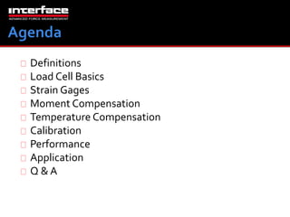
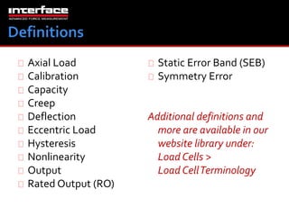
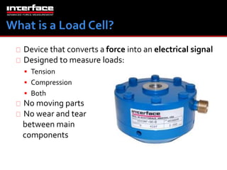
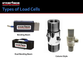
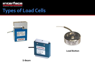
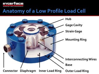
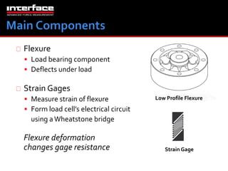
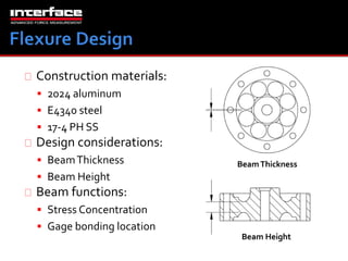
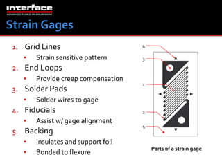
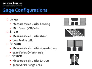
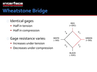
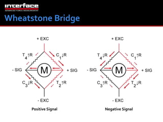
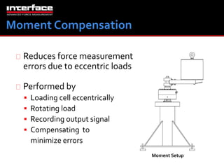
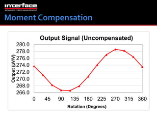
Interface Webinar Wednesday 
Load Cells 101 
with Albert Luna
Definitions 
Load Cell Basics 
Strain Gages 
Moment Compensation 
Temperature Compensation 
Calibration 
Performance 
Application 
Q & A
Axial Load 
Calibration 
Capacity 
Creep 
Deflection 
Eccentric Load 
Hysteresis 
Nonlinearity 
Output 
Rated Output (RO) 
Static Error Band (SEB) 
Symmetry Error 
Additional definitions and 
more are available in our 
website library under: 
Load Cells > 
Load Cell Terminology
Device that converts a force into an electrical signal 
Designed to measure loads: 
 Tension 
 Compression 
 Both 
No moving parts 
No wear and tear 
between main 
components
Bending Beam 
Dual Bending Beam 
Column Style
S-Beam 
Load Button
Hub 
Strain Gage 
Mounting Ring 
Interconnecting Wires 
Base 
Diaphragm Inner Load Ring Outer Load Ring 
Connector 
Gage Cavity
Flexure 
 Load bearing component 
 Deflects under load 
Strain Gages 
 Measure strain of flexure 
 Form load cell’s electrical circuit 
using a Wheatstone bridge 
Low Profile Flexure 
Flexure deformation 
changes gage resistance Strain Gage
Construction materials: 
 2024 aluminum 
 E4340 steel 
 17-4 PH SS 
Design considerations: 
 Beam Thickness 
 Beam Height 
Beam functions: 
 Stress Concentration 
 Gage bonding location 
Beam Thickness 
Beam Height
1. Grid Lines 
▪ Strain sensitive pattern 
2. End Loops 
▪ Provide creep compensation 
3. Solder Pads 
▪ Solder wires to gage 
4. Fiducials 
▪ Assist w/ gage alignment 
5. Backing 
4 
3 
1 
2 
5 
▪ Insulates and support foil 
▪ Bonded to flexure Parts of a strain gage
Linear 
 Measure strain under bending 
 Mini Beam (MB Cells) 
Shear 
 Measure strain under shear 
 Low Profile cells 
Poisson 
 Measure strain under normal stress 
 2100 Series Column cells 
Chevron 
 Measure strain under torsion 
 5400 Series flange cells
Identical gages 
 Half in tension 
 Half in compression 
Gage resistance varies: 
 Increases under tension 
 Decreases under compression
Wire under tension strains: 
 Cross section decreases 
 Decreased current flow 
 Increased electrical resistance 
Wire under compression strains: 
 Cross section increases 
 Increased current flow 
 Decreased electrical resistance
No deflection in gage area 
Designed to be weakest section 
Gage 
Areas 
Low Profile Load Cell Section View
Deforms under load 
Shear stress concentration 
Compression Tension 
Strain lines in gage area 
(Not to scale)
Grid lines parallel to strain lines 
Gage is under tension 
Resistance increases 
Shear gage under tension
Grid lines perpendicular to strain lines 
Gage is under compression 
Resistance decreases 
Gage under compression
Positive Signal Negative Signal
Proprietary Interface foil strain gages are thermally 
matched to the load cell material. 
As a result our load cells do not require modulus 
compensation resistors. 
This allows for far superior temperature 
performance along with higher output (typically 
4mV/V) at lower mechanical strain levels. 
Higher output means higher resolution and better 
signal-to-noise ratio.
Reduces force measurement 
errors due to eccentric loads 
Performed by 
 Loading cell eccentrically 
 Rotating load 
 Recording output signal 
 Compensating to 
minimize errors 
Moment Setup
280.0 
278.0 
276.0 
274.0 
272.0 
270.0 
268.0 
266.0 
Output Signal (Uncompensated) 
0 45 90 135 180 225 270 315 360 
Output (μV/V) 
Rotation (Degrees)
222.5 
222.0 
221.5 
221.0 
220.5 
220.0 
219.5 
219.0 
Output Signal (Compensated) 
0 45 90 135 180 225 270 315 360 
Output (μV/V) 
Rotation (Degrees)
Reduces force measurement 
errors due to ambient 
temperature changes 
Performed by 
 Recording output signal 
▪ Cold – Hot (15 – 115F) 
 Under a No-Load condition 
 Adding compensating wire to 
minimize temperature induced errors
Performed to verify 
load cell meets 
performance parameters 
 Hysteresis 
 Non-linearity 
 Static Error Band 
Calibration Setup
Questions?
Thank You!

Load Cells 101 Presentation

  • 1.
    Interface Webinar Wednesday Load Cells 101 with Albert Luna
  • 2.
    Definitions Load CellBasics Strain Gages Moment Compensation Temperature Compensation Calibration Performance Application Q & A
  • 3.
    Axial Load Calibration Capacity Creep Deflection Eccentric Load Hysteresis Nonlinearity Output Rated Output (RO) Static Error Band (SEB) Symmetry Error Additional definitions and more are available in our website library under: Load Cells > Load Cell Terminology
  • 4.
    Device that convertsa force into an electrical signal Designed to measure loads:  Tension  Compression  Both No moving parts No wear and tear between main components
  • 5.
    Bending Beam DualBending Beam Column Style
  • 6.
  • 7.
    Hub Strain Gage Mounting Ring Interconnecting Wires Base Diaphragm Inner Load Ring Outer Load Ring Connector Gage Cavity
  • 8.
    Flexure  Loadbearing component  Deflects under load Strain Gages  Measure strain of flexure  Form load cell’s electrical circuit using a Wheatstone bridge Low Profile Flexure Flexure deformation changes gage resistance Strain Gage
  • 9.
    Construction materials: 2024 aluminum  E4340 steel  17-4 PH SS Design considerations:  Beam Thickness  Beam Height Beam functions:  Stress Concentration  Gage bonding location Beam Thickness Beam Height
  • 10.
    1. Grid Lines ▪ Strain sensitive pattern 2. End Loops ▪ Provide creep compensation 3. Solder Pads ▪ Solder wires to gage 4. Fiducials ▪ Assist w/ gage alignment 5. Backing 4 3 1 2 5 ▪ Insulates and support foil ▪ Bonded to flexure Parts of a strain gage
  • 11.
    Linear  Measurestrain under bending  Mini Beam (MB Cells) Shear  Measure strain under shear  Low Profile cells Poisson  Measure strain under normal stress  2100 Series Column cells Chevron  Measure strain under torsion  5400 Series flange cells
  • 12.
    Identical gages Half in tension  Half in compression Gage resistance varies:  Increases under tension  Decreases under compression
  • 13.
    Wire under tensionstrains:  Cross section decreases  Decreased current flow  Increased electrical resistance Wire under compression strains:  Cross section increases  Increased current flow  Decreased electrical resistance
  • 14.
    No deflection ingage area Designed to be weakest section Gage Areas Low Profile Load Cell Section View
  • 15.
    Deforms under load Shear stress concentration Compression Tension Strain lines in gage area (Not to scale)
  • 16.
    Grid lines parallelto strain lines Gage is under tension Resistance increases Shear gage under tension
  • 17.
    Grid lines perpendicularto strain lines Gage is under compression Resistance decreases Gage under compression
  • 18.
  • 19.
    Proprietary Interface foilstrain gages are thermally matched to the load cell material. As a result our load cells do not require modulus compensation resistors. This allows for far superior temperature performance along with higher output (typically 4mV/V) at lower mechanical strain levels. Higher output means higher resolution and better signal-to-noise ratio.
  • 20.
    Reduces force measurement errors due to eccentric loads Performed by  Loading cell eccentrically  Rotating load  Recording output signal  Compensating to minimize errors Moment Setup
  • 21.
    280.0 278.0 276.0 274.0 272.0 270.0 268.0 266.0 Output Signal (Uncompensated) 0 45 90 135 180 225 270 315 360 Output (μV/V) Rotation (Degrees)
  • 22.
    222.5 222.0 221.5 221.0 220.5 220.0 219.5 219.0 Output Signal (Compensated) 0 45 90 135 180 225 270 315 360 Output (μV/V) Rotation (Degrees)
  • 23.
    Reduces force measurement errors due to ambient temperature changes Performed by  Recording output signal ▪ Cold – Hot (15 – 115F)  Under a No-Load condition  Adding compensating wire to minimize temperature induced errors
  • 25.
    Performed to verify load cell meets performance parameters  Hysteresis  Non-linearity  Static Error Band Calibration Setup
  • 32.
  • 33.