
Recommended
Recommended
More Related Content
What's hot
What's hot (20)
Similar to Partial Discharge Analysis in High Voltage Current Transformers
Similar to Partial Discharge Analysis in High Voltage Current Transformers (20)
More from IRJESJOURNAL
More from IRJESJOURNAL (20)
Recently uploaded
Recently uploaded (20)
Partial Discharge Analysis in High Voltage Current Transformers
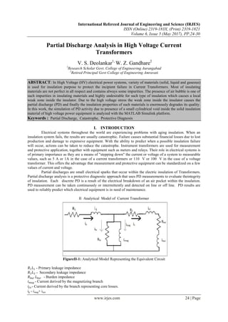
- 1. International Refereed Journal of Engineering and Science (IRJES) ISSN (Online) 2319-183X, (Print) 2319-1821 Volume 6, Issue 5 (May 2017), PP.24-30 www.irjes.com 24 | Page Partial Discharge Analysis in High Voltage Current Transformers V. S. Deolankar1, W. Z. Gandhare2 1 Research Scholar Govt. College of Engineering Aurangabad 2 Retired Principal Govt College of Engineering Amravati ABSTRACT: In High Voltage (HV) electrical power systems, variety of materials (solid, liquid and gaseous) is used for insulation purpose to protect the incipient failure in Current Transformers. Most of insulating materials are not perfect in all respect and contains always some impurities. The presence of air bubble is one of such impurities in insulating materials and highly undesirable for such type of insulation which causes a local weak zone inside the insulator. Due to the high voltage stress the weak zone inside the insulator causes the partial discharge (PD) and finally the insulation properties of such materials is enormously degrades its quality. In this work, the simulation of PD activity due to presence of a small cylindrical void inside the solid insulation material of high voltage power equipment is analyzed with the MATLAB Simulink platform. Keywords : Partial Discharge, Catastrophe, Protective Diagnosis I. INTRODUCTION Electrical systems throughout the world are experiencing problems with aging insulation. When an insulation system fails, the results are usually catastrophic. Failure causes substantial financial losses due to lost production and damage to expensive equipment. With the ability to predict when a possible insulation failure will occur, actions can be taken to reduce the catastrophe. Instrument transformers are used for measurement and protective application, together with equipment such as meters and relays. Their role in electrical systems is of primary importance as they are a means of "stepping down" the current or voltage of a system to measurable values, such as 5 A or 1A in the case of a current transformers or 110 V or 100 V in the case of a voltage transformer. This offers the advantage that measurement and protective equipment can be standardized on a few values of current and voltage. Partial discharges are small electrical sparks that occur within the electric insulation of Transformers. Partial discharge analysis is a protective diagnostic approach that uses PD measurements to evaluate theintegrity of insulation. Each discrete PD is a result of the electrical breakdown of an air pocket within the insulation. PD measurement can be taken continuously or intermittently and detected on line or off line. PD results are used to reliably predict which electrical equipment is in need of maintenance. II Analytical Model of Current Transformer FigureII-1: Analytical Model Representing the Equivalent Circuit 𝑅1 𝐿1 - Primary leakage impedance 𝑅2 𝐿2 - Secondary leakage impedance 𝑅 𝑏𝑢𝑟 𝐿 𝑏𝑢𝑟 - Burden impedance 𝑖 𝑚𝑎𝑔 - Current derived by the magnetizing branch 𝑖𝑓𝑒 - Current derived by the branch representing core losses. ip - imag+ isec
- 2. Partial Discharge Analysis In High Voltage Current Transformers www.irjes.com 25 | Page The flux changes with magnetic current. Writing the equation for current flowing in magnetizing path with initial data and w.r.t time new. The flux will be variable. II. PARTIAL DISCHARGE MEASUREMENT IN CURRENT TRANSFORMERS Acceptable limit is between 5 pc to 10 pc. Out of the results measured segregated CT where Partial Discharge is more then 10 pc. After the Analysis, following reasons observed which leads to higher PD 1. High Vacuum Level 2. Low Temperature 3. High Oil Flow Rate During manufacturing process the parameters specified are: Vacuum Level 5x10-4 = 0.5 mbar Temperature 138O Oil flow rate Initial for 6 hrs 0.5 lph Middle for 8 hrs 4 lph Final for 8 hrs 14 lph a) Low vacuum level less than 0.5 mbar: Low vacuum extracts less moisture. Retained moisture leads to Partial Discharge. Evacuation system is designed for high vacuum and low temp. If vacuum is high then evaporation rate is less than 100O C .Dielectric strength of impregnated insulation should be more, if not voids will be formed b) Low temp of oil less than138O C : Because of low temp the moisture not removed, which lead to the formation of bubbles .The insulation paper layers are around 22 nos, the temp must reach the inner most layer and remove the moisture contents. The extent of moisture not removed will lead to content of water resulting into discharge phenomenon c) Effect of High Oil flow rate: High flow rate of oil will lead to the formation of bubbles and air will trap. Hence oil flow should be slow to the extent paper absorbs oil. If it is more paper will not absorb oil completely and simultaneously air bubble formation in oil tank. The elasticity of paper that provides compression pressure on inner layer will not allow the air to trap. The paper used in the sequence of Non stretched, Light Stretched and crepe paper. Non uniform succession in paper insulation absorption rate should match oil filling rate otherwise it will lead to the formation of voids. Voids are the potential for partial discharge III. ELECTRICAL CIRCUIT FOR ILLUSTRATION OF PD MEASUREMENT FigureIV-1: Equivalent Circuit Model In the equivalent circuit model The three capacitance are considered. Cc corresponds to the cylindrical void present inside the solid insulation, Cb corresponds to the capacitance of the remaining series insulation with void (Cc) Ca corresponds to the capacitance of the remaining discharge-free insulation of the rest of the solid insulator. This circuit is energized with ac voltage source, a recurrent discharge occurs. Capacitance of the void Cc is charged which is responsible for occurrence of break down.
- 3. Partial Discharge Analysis In High Voltage Current Transformers www.irjes.com 26 | Page IV. SIMULINK MODEL FOR DETECTION OF PARTIAL DISCHARGE FigureV-1: Simulation Model of Current Transformers in Steady State To evaluate the fundamental quantities of PD pulse, a simple equivalent capacitor circuit of solid insulator having cylindrical void is taken into consideration for this work. In the equivalent circuit the capacitance Cc corresponds to the cylindrical void present inside the solid insulation, Cb corresponds to the capacitance of the remaining series insulation with void (Cc) and Ca corresponds to the capacitance of the remaining discharge-free insulation of the rest of the solid insulator. Generally, (Ca>>Cb>>Cc). According to the size of void in insulation sample (epoxide resin), a cylindrical void of height of 4 mm and a radius of 2 mm is used in a cube sample (30mm ×30mm ×5mm) in this model. The void is located in the centre of the insulation sample. In this study the value of the void model and the other high voltage equipment for measurement of PD inside the solid insulation is taken as depicted in Table 1 respectively. Sr. Components Value/ Rating 1 HV transformer 0.23/5 kV, 50 kVA 2 HV measuring capacitor 200/1500 pF 3 HV coupling capacitor 1000 μF 4 Detector circuit resistance 50 Ω 5 Detector circuit inductance 0.63 mH 6 Detector circuit capacitance 0.47 μF Table 1 V-1. Results and Discussions i) Relationship of volume of void with apparent charge: Figure VI-1: A Linear Relationship of Volume of Void with Apparent Charge Another study has been made in this work which is the relation between the apparent charge and the volume of the void. It is observed that the apparent charge is also a function of volume geometry of the cylindrical void model. It is also observed that, the volume is directly related to apparent charge which is shown in Fig. . It is observed from simulation result that the relation between void volume and apparent charge curve is a linear one.
- 4. Partial Discharge Analysis In High Voltage Current Transformers www.irjes.com 27 | Page ii) Relationship of diameter of void with apparent charge: To study the PD activity due to presence of cylindrical void inside the solid insulation, apparent charge and size of the void is also considered in this work. In Fig. above it is observed that with the increase of the diameter of the cylindrical void apparent charge is increase. It is understand from the above result that the magnitude of the PD is also vary as the apparent charge is varying with changing the void height, diameter and void volume. FigureVI-2: Relationship of Diameter of Void with Apparent Charge In this work, the sample dimension is (30×30×5) mm and height of the void has taken less than 5 mm i.e., 4 mm and radius of the void has taken 2 mm. The void capacitances of the solid insulation are calculated by using the equations. The amplitude of the PD pulse is changing with the size of the void which is shown in Fig. The void capacitance is changes with the changing the radius of the void keeping the void height same. iii) PD pulse observed with 5 kV applied voltage: Changing the void height and keeping the void radius constant (2 mm) the amplitude of the PD pulse is also changes. It also proves that the dimensional configuration of void parameter affects the changes in the PD amplitude while 5 kV applied voltage is provided between the plate electrodes. To simulate the PD activity inside the solid insulation medium a MATLAB Simulink model is considered in this work. An increasing voltage of 0-30 kV is applied between the void models to observe the PD activity inside the solid insulation. It is observed that with application of 0- 4 kV between the cylindrical void models no PD was found. The field intensity within the void not exceeds beyond the breakdown strength of gas in void below the applied voltage of 5 kV. Further with increase of high voltage between the test object PDs are appearing having small amplitude. At the applied voltage of 5 kV PDs are found due to presence of void inside the solid insulation. With the applied voltage of 5 kV the field intensity within the void exceeds the breakdown strength of gas in void and PD pulse is observed which is shown in Fig below : Figure VI-3: PD Pulse Observed with 5 kV Applied Voltage Partial discharge can be represented by two quantities: partial discharge magnitude in pC and position of partial discharge pulse related to the phase of the power frequency wave. If the PD measurement is extended to the duration of the one half cycle of the sine wave and more PD occur, integrated quantities for the positive
- 5. Partial Discharge Analysis In High Voltage Current Transformers www.irjes.com 28 | Page and the negative half of the sine wave can be calculated. All these quantities can be analyzed here as a function of time and as a function of the phase angle. To identify the position of PDs with respect to the phase angle, phase resolve partial discharge (PRPD) detection technique is an important tool for monitoring of HV power equipment. To distinguish the PDs with other discharges, the presence of PD pulses in the different quadrant gives the cause of occurrence of PDs. The applied voltage of 5 kV and along with the PD pulse is shown in Fig. below. It is observed that PD pulse is appears nearly 90 degree phase angle in positive half cycle and nearly 270 degree phase angle in negative half cycle of the 5 kV applied voltage which is shown in the Fig . Due to lower rate of applied voltage between the test object is not enough to cause field intensity within the void in excess of PD inception strength. Therefore, PDs are mostly appearing at 90 degree phase angle and 270 degree phase angle of the applied voltage where the maximum amplitude of the applied voltage is reached. Figure VI-4: Observed PD Pulse with 5 kV Applied Voltage between the Test Object To observe the characteristics of the PD pulse an analysis has taken for observing the pulse rise time, fall time and its pulse width for 5 kV applied voltage. The PD pulses which have maximum amplitudes are taken for calculating rise time, fall time and its pulse width VII. SHORT CIRCUIT IN POWER SYSTEM Short circuit in power systems is serious fault. The short circuit current must be calculated for the choice of electrical equipment’s and the setting of power system protection. An arc presents usually at the fault location in power systems. The fault arc could destroy electrical equipment and threaten human life. It is important to calculate the arc fault current for reducing loss. Faults occur when equipment insulation fails, due to system over voltages, lightning, contamination or other mechanical causes. Single line-to-ground faults account for about 90% of the total faults. FigureVII-1: Single Line -to-Ground Fault Consider a single line-to-ground fault from phase a to ground at the general three-phase bus shown in Figure 1. For generality, a fault impedance Z_f is included. In the case of a bolted fault, Z_f=0, whereas for an
- 6. Partial Discharge Analysis In High Voltage Current Transformers www.irjes.com 29 | Page arcing fault, Z_f is the arc impedance. In the case of a insulator flashover, Z_f equals the total fault impedance between the line and ground, including the impedance of the arc. The Line Fault Model consists of 145 kV 50 Hz three phase source block feeding to a three phase parallel RLC load. There is a fault block located at the source feeder line to simulate single line to ground fault. In this simulation short circuit fault current goes up to 28 KA as shown in figure VII-4. FigureVII-3: Three phase voltage waveform for Phase-A to ground condition FigureVII-4: SC Fault Current VIII. CONCLUSIONS The PD activity inside the solid insulation is highly depends on the entire geometry of the void presence inside the oil and paper insulation model. PD increases with the increase of applied voltage inside the solid insulation. Investigated the maximum PD magnitude, number of PDs and number of other PD related parameters like PD distribution, frequency content of obtained PD pulse by using phase resolve partial discharge (PRPD) measurement technique. Based on the developed SIMULINK model and calculated parameters used for oil and insulation papers sample, the characteristic of PDs has been studied. This study will ensure to predict the quality of the insulation used for high voltage Current Transformers 145 kV. REFERENCES [1] G. C. Crichton, P. W. Karlsson and A. Pedersen, “Partial Discharges in Ellipsoidal and Spherical Voids”, IEEE Trans. on Dielectric and Electrical Insulation, Vol. 24, No. 2, April 1989 , pp. 335-342. [2] R. J. Van Brunt, “Physics and Chemistry of partial discharges and corona”, IEEE Trans. on dielectric and Electrical Insulation, Vol. 1, No. 5, October 1994 , pp. 761-784. [3] M. G. Danikas, “Some New Relationships and a Scaling Law Regarding Partial Discharges in Spherical Cavities Enclosed in Solid Insulation”, ActaElectrotechnicaNapocensis, Vol. 39, No. 1, 1998 pp. 5-9. [4] A. A. Paithankar, A. D. Mokashi, “Can PD Phenomena be Analysed by Deterministic Chaos” EIC’97,Chicago, (IEEE) Conference preceedings, 1997 , pp. 283-290.
- 7. Partial Discharge Analysis In High Voltage Current Transformers www.irjes.com 30 | Page [5] N. Kolev, P. Darjanov, E. Gadjeva and D. Darjanova, “Partial Discharge Phenomena Simulation using General-purpose Analysis Program”, Proc of 6th IEEE International Conference on Conduction and Breakdown in solid Dielectrics-ICSD 98, June 22-25, Vasteras, Sweden, 1998, pp. 149-152. [6] C. Y. Ren, Y. H. Cheng, P. Yan, Y. H. Sun, T. Shao, “Simulation of Partial Discharges in Single and Double voids Using SIMULINK”, Journal of Xi’an Jiatong University, Vol. 38, No. 10, 2004 , pp. 120-122. [7] N. Kolev, P. Darjanov, E. Gadjeva and D. Darjanova, “An approach to develop a partial discharge investigation”, Proc. of the IEEE Electrical Insulation Conference and Electrical Manufacturing and Coil Windings conference, Chicago, 1997 , pp. 507-510. [8] L. Satish, and W. S. Zaengl, “Artificial Neural Networks for recognisation of 3D Partial Discharge patterns”, IEEE Trans. on Dielectrics and Electrical Insulation, Vol. 1, No. 2, April 1994, pp 265-275. [9] F. Gutleisch and L. Niemeyer, “Measurement and Simulation of PD in Epoxy Voids”, IEEE Transcation on Dielectrics and Electrical insulation, Vol. 2, No. 5 , 1995, pp. 729-743. [10] R. Bartnikas, “Partial Discharge their mechanism, Detection and Measurement”, IEEE Trans. Electr. Insul. Vol. 9 2002 , pp. 763-808. [11] S. Karmakar, N. K. Roy, P. Kumbhakar, “Partial Discharge Measurement of Transformer with ICT Facilities”, Third International Conference on Power Systems, Kharagpur, India, December 27 -29, 2009 pp.116-2120 [12] S. Karmakar, N. K. Roy and P. Kumbhakar “Monitoring of high voltage power transformer using direct Optical Partial Discharges detection technique”, journal of Optics, Vol. 38, No. 4, , 2009 pp.207- 215. [13] E. Kuffel,W. S. Zaengl, J.Kuffel, High voltage engineering: fundamentals, Published by Eleslever, ISBN 0-7506-3634-3, second edition, 2005 2009 pp.149 -152 Author :