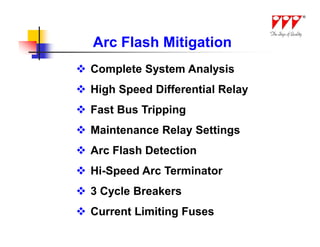
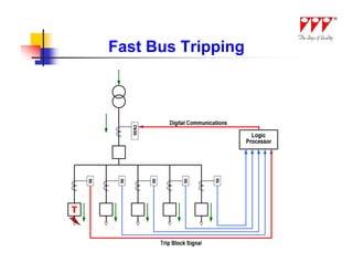
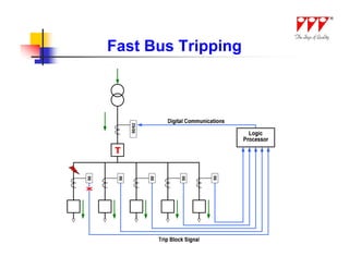
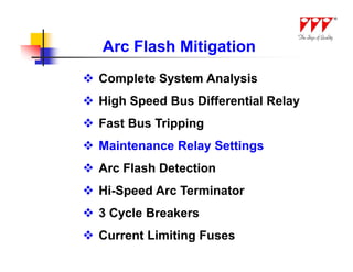
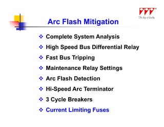
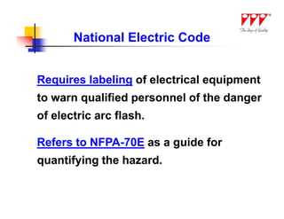
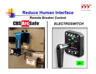
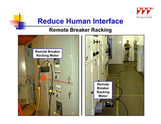
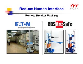
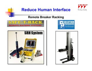
This document discusses strategies for mitigating arc flash hazards in metalclad switchgear. It covers arc flash standards, prevention techniques, protection methods, and mitigation approaches. Key topics include implementing fast bus tripping, high speed differential relays, maintenance relay settings, arc flash detection, current limiting fuses, and reducing the human interface with remote racking and control. The goal is to reduce incident energy levels and protect personnel through engineering and procedural controls.


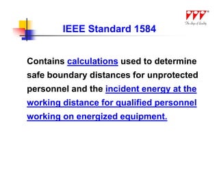
![IEEE Standard 1584
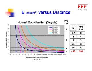
Incident Energy Calculation for
Arc Flash in a Cubic Box
E =1038.7D-1.4738 x T[0.0093F2-0.3453F+5.9675]
E = Incident Energy in cal/cm2
D = Distance to arcing point
T = Time to clear arcing fault
F = Available bolted fault short circuit current](https://image.slidesharecdn.com/ppparcflashpresentationv5-1-120502225507-phpapp02/85/20120504-LISAT-slides-Dube-6-320.jpg)
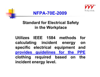


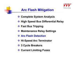
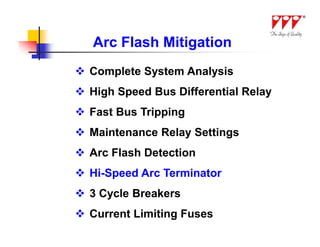
![Arc Flash Mitigation
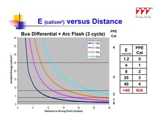
Incident Energy Calculation
E =1038.7D-1.4738 x T[0.0093F2-0.3453F+5.9675]
E = Incident Energy in cal/cm2
D = Distance to arcing point
T = Time to clear arcing fault
F = Available short circuit current](https://image.slidesharecdn.com/ppparcflashpresentationv5-1-120502225507-phpapp02/85/20120504-LISAT-slides-Dube-66-320.jpg)