SYSTEM ON PROGRAMMABLE CHIP FOR PERFOMANCE ESTIMATION OF LOOM MACHINE
TMW09_03F3_proof
1. MARCH 2009 1TEST & MEASUREMENT WORLD www.tmworld.com
A
utomated test stations don’t always need
proprietary test tools. Using a microcon-
troller, a PC, and free software tools, we de-
veloped an automated test station to test and align
motion sensors.Test engineers can operate the sys-
tem from any Web browser in the company net-
work and can also check the status of a unit under
test or retrieve data on a previously tested sensor
module.
The motion-sensor module is an optical sensor
that uses illuminating LEDs and focused detectors
to sense moving objects.The module uses one bank
of LEDs to illuminate a target and another bank of
32 detectors to sense motion.The sensor’s output is
a bit vector indicating the current state of each de-
tector.The outputs of many such sensors are as-
sembled into a profile of the moving object for
identification by a pattern-matching system.
To function properly, the sensor module’s LEDs
and detectors need to be mechanically aligned,
something that isn’t practical to do by hand.Thus,
we built an automated system that provides consis-
tent alignment and also tests each sensor’s signal-
conditioning and communications lines.The block
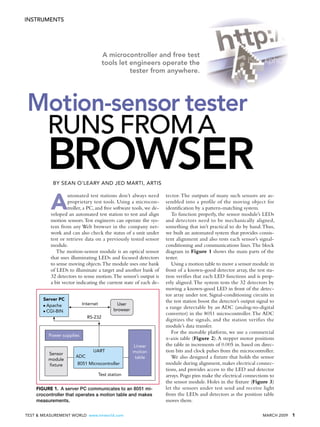
diagram in Figure 1 shows the main parts of the
tester.
Using a motion table to move a sensor module in
front of a known-good detector array, the test sta-
tion verifies that each LED functions and is prop-
erly aligned.The system tests the 32 detectors by
moving a known-good LED in front of the detec-
tor array under test. Signal-conditioning circuits in
the test station boost the detector’s output signal to
a range detectable by an ADC (analog-to-digital
converter) in the 8051 microcontroller.The ADC
digitizes the signals, and the station verifies the
module’s data transfer.
For the movable platform, we use a commercial
x-axis table (Figure 2).A stepper motor positions
the table in increments of 0.005 in. based on direc-
tion bits and clock pulses from the microcontroller.
We also designed a fixture that holds the sensor
module during alignment, makes electrical connec-
tions, and provides access to the LED and detector
arrays. Pogo pins make the electrical connections to
the sensor module. Holes in the fixture (Figure 3)
let the sensors under test send and receive light
from the LEDs and detectors as the position table
moves them.
A microcontroller and free test
tools let engineers operate the
tester from anywhere.
Motion-sensor tester
RUNS FROM A
BROWSERBY SEAN O’LEARY AND JED MARTI, ARTIS
Server PC
● Apache
● CGI-BIN
Power supplies
Sensor
module
fixture
User
browser
Linear
motion
tableADC
UART
RS-232
Test station
8051 Microcontroller
Internet
FIGURE 1. A server PC communicates to an 8051 mi-
crocontroller that operates a motion table and makes
measurements.
INSTRUMENTS
2. 2 MARCH 2009 www.tmworld.com TEST & MEASUREMENT WORLD
Using a Web-based
system
The circuits that interface
with the motor driver are
located on the station’s
printed-circuit board (Fig-
ure 4), which also contains
the limit sensors, the drivers
for the optical devices, and
the circuits for the sensor
module.The 8051 has a 10-
bit ADC, 8 kbytes of RAM,
24 I/O pins, and two
UARTs (universal asynchro-
nous receiver-transmitters).An external
memory chip extends the total memory
to 64 kbytes.The 8051’s serial port com-
municates between the test-system hard-
ware and a PC running Apache Web
Server under Linux.This approach has
several advantages:
● The Apache Web Server software is
easy to set up, secure, and free; it runs
under Linux or Windows.
● Connecting the server to
a serial port through a CGI-
BIN (common gateway in-
terface-binary) script is easy.
A small C program on the
server sends a command to
the test system to start the
test.The program also inter-
prets commands and re-
trieves content such as bit-
mapped images and HTML
text. Linux C and C++
compilers are free.
● The 8051 microcontroller
doesn’t need to support a
file system, Internet proto-
col, or other Web interfaces.
The test system's embed-
ded microcontroller (Figure
1) connects to the server
through a CGI-BIN pro-
gram’s serial port.Test results,
images, and text are stored in
a data directory on the server
for immediate display or recall.
The server sends a command over the
serial port that tells the station to execute
the test. Once the server sends the start
command, the station code runs through
an entire test.As the microcontroller col-
lects data,it generates tables,charts,and bit-
mapped images. Once an image is com-
pleted, the microcontroller sends it to the
server through the CGI-BIN program.
A simple welcome screen from the
Web server tells the user when to steer
the browser to the address assigned to
the station. Anyone on the corporate
network has access to this start-up screen.
From the main Web page, a user can:
● see a statistics page indicating the
number of devices tested and examine a
summary of the results;
● view reports, by serial number, for
devices whose testing has been com-
pleted; and
● initiate the test protocol.
Once testing is complete, the server
displays the test results for all 32 sensors
as a color graph on the Web page.This
report, including all the graphs, is gener-
ated by the microcontroller and subse-
quently transferred to the server.This
Web page contains tables and graphs de-
tailing the results of the test
as well as any messages that
indicate errors or anomalies.
The Web-based system
did introduce one obstacle
that we had to overcome.
When the user initiates the
test protocol, the station
opens a new Web page and
begins writing to it.As tests
complete, the server adds
additional information to
the Web page.We encoun-
tered a problem regarding
dead time in communicating with the
Web page.Web pages can time out in 4
to 5 min if they don’t receive new infor-
mation. Because one test took 6 min to
complete, we wrote some code to ping
the browser periodically to prevent time-
outs, and this lets the system complete
the page.
Even though our test system does not
permit motion beyond program limits,
it is always wise to include
limit sensors when building
a motion-controlled tester.
Limit sensors indicate that
the table is nearing the end
of its travel.We added limit
sensors to allow the micro-
controller to cut power
when the table reaches the
end of its travel. In fact,
those sensors proved useful
during software develop-
ment when the table went
too far.
Overall, we have been
very happy with the results
from our testers.While the
first time through this ap-
proach presented certain
challenges, we now have a
test-setup template that we
can reuse when designing
new test stations. In the long
run, our system has reduced
development time as well as training
time and overall costs. T&MW
Sean O’Leary is a senior electrical engi-
neer at Artis. He received his ME in electri-
cal engineering from the University of Utah
in 1999.
Jed Marti is chief scientist of Artis. He
received a PhD in computer science from
the University of Utah in 1980.
FIGURE 2. A linear motion table aligns the sensor arrays to LEDs
and detectors in the test fixture.
INSTRUMENTS
FIGURE 3. A test fixture contains holes that pass light between
32 sensors and a test board.
FIGURE 4. Known-good LEDs in the test fixture transmit light to a
sensor module under test, and known-good detectors detect the
light that the module transmits.