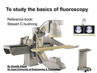
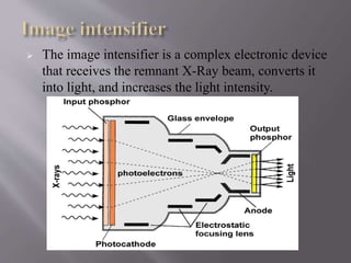
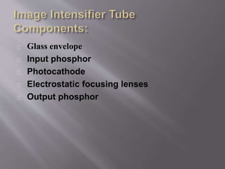
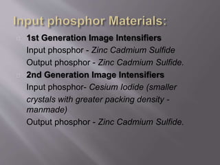
The document summarizes the components and functioning of a fluoroscope. A fluoroscope uses x-rays to visualize the motion of internal structures in real-time. It consists of an x-ray generator, tube, collimator, filters, table, grid, image intensifier, optical coupling and television system. The image intensifier converts x-rays into light photons, which are converted into an electronic signal via a television camera or CCD and displayed on a monitor. Spot films can also be obtained from fluoroscopy for later examination.


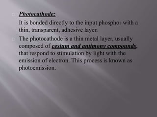


![Attack surfaces and attack tress[inform]](https://cdn.slidesharecdn.com/ss_thumbnails/lecture03-260108015941-a4dee53b-thumbnail.jpg?width=640&height=640&fit=bounds)