Strength of Double Angle Bolted Tension Members (38
•
10 likes•4,902 views

05-Strength of Double Angle Bolted Tension Members (Steel Structural Design & Prof. Shehab Mourad)

Recommended
Recommended
More Related Content
What's hot
What's hot (20)
Similar to Strength of Double Angle Bolted Tension Members (38
Similar to Strength of Double Angle Bolted Tension Members (38 (20)
More from Hossam Shafiq II
More from Hossam Shafiq II (20)
Recently uploaded
Recently uploaded (20)
Strength of Double Angle Bolted Tension Members (38
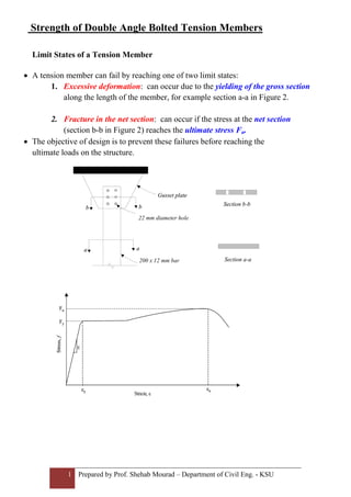
- 1. 1 Prepared by Prof. Shehab Mourad – Department of Civil Eng. - KSU Strain, ε εy εuεy εu Stress,f Fy Fu E Strain, ε εy εuεy εu Stress,f Fy Fu εy εuεy εu Stress,f Fy Fu E Strength of Double Angle Bolted Tension Members Limit States of a Tension Member • A tension member can fail by reaching one of two limit states: 1. Excessive deformation: can occur due to the yielding of the gross section along the length of the member, for example section a-a in Figure 2. 2. Fracture in the net section: can occur if the stress at the net section (section b-b in Figure 2) reaches the ultimate stress Fu. • The objective of design is to prevent these failures before reaching the ultimate loads on the structure. b b aa Gusset plate b b aa 200 x 12 mm bar Gusset plate 22 mm diameter hole Section a-a Section b-b Section a-a Section b-b
- 2. 2 Prepared by Prof. Shehab Mourad – Department of Civil Eng. - KSU Fig 1. Bolted tension member 1) Yielding of gross area 2) Fracture at net area Fig 2 Dimension of cross section Fu = Ultimate Tensile Strength of angles Net area = Anet = Gross area – area of holes = {Ag – ∑ dh t } dh = hole diameter = bolt diameter + 3mm (or 1/8 in) Ag = Gross Area of angles Fy = Yield Tensile Strength of angles Ø Rn = 0.75* Ae * Fu Ø Rn = 0.9* Fy * Ag Effective Area , Ae = Anet * U y* y" t g2 g1 b h tg section (1-1) hg Pu Pu SS Le2Le1 1 1 t Le1 S S Lc
- 3. 3 Prepared by Prof. Shehab Mourad – Department of Civil Eng. - KSU Shear Lag effect • Shear lag occurs when the tension force is not transferred uniformly to all elements of the cross-section. This will occur when some elements of the cross-section are not connected. Strength reduction factor , U = (1 – x / Lc ) < 0.9 Lc = For bolted connections, l is the distance between the first and last fasteners. For staggered bolts, the out-to-out dimension is used .
- 4. 4 Prepared by Prof. Shehab Mourad – Department of Civil Eng. - KSU Strength reduction factor , U = (1 – x / Lc ) < 0.9 x' = c.g of angle along horizontal leg y' = c.g of angle along vertical leg y* = c.g of the shaded area of angle y* = Ag (one angle) * y' – {(Ye)* tangle}* (hangle– [Ye /2] ) Ag – (Ye) * tangle • SBC 306 gives values of U for some connection configurations that can be used instead of using Equation . These values are summarized in Table below. 1 For W, M, and S shapes or Tee cut from these shapes With flange connected with 3 or more fasteners per line in the direction of loading bf ≥ 2/3d ….. U=0.9 b f < 2/3d …. U=0.85 2 With web connected with 4 or more fasteners per line in the direction of loading U=0.7 3 For all other shapes including built up sections with at least 3 fasteners per line in the direction of loading U=0.85 4 For all members with only two fasteners per line U=0.75 5 For all tension members where tension load is transmitted onlybytransverse welds to some but not all of the cross-sectional elements: Ae=UA, A=area of the directly connected elements. U = 1.0 6 For plates where tension load is transmitted by longitudinal welds only. For l ≥ 2w For 2w>l ≥ 1.5w For 1.5w>l ≥ w U = 1.00 U = 0.87 U = 0.75 x' h g1 ye y* y" dh t t y' l w
- 5. 5 Prepared by Prof. Shehab Mourad – Department of Civil Eng. - KSU T T (a) (b) (c) T T Tension failure plane (a) (b) 3) Block shear in angle • For some connection configurations, the tension member can fail due to ‘tear-out’ of material at the connected end. This is called block shear. case 1 case 2 Fig 3 Block shear failure in bolted connection Lt Lv 1 Lt Lv 1 P Lc
- 6. 6 Prepared by Prof. Shehab Mourad – Department of Civil Eng. - KSU • Block shear strength is determined as the sum of the shear strength on the shear path and the tensile strength on a tension path: • Block shear strength = net section fracture strength on shear path + gross yielding strength on the tension path OR Block shear strength = gross yielding strength of the shear path + net section fracture strength of the tension path Agt = Lt * ∑ tangle Ant = ( Lt - ∑ dh ) * ∑ t angle Agv = Lv * ∑ tangle Anv = ( Lv - ∑ dh) * ∑ tangle Where Lv = 2*Lv1 (for given case 1) Lv = Lv1 (for given case 2) Agt = gross Area in tensile plane for 2 angle Ant = net Area in tensile for 2 angle Agv = gross Area in shear for 2 angle Anv = net Area in shear for 2 angle Fu = Ultimate Tensile Strength of angles Fy = Yield Tensile Strength of angles Effect of Staggered bolt holes on net area If 0.6 * Fu * Anv > Fu * Ant , Ø Rn = 0.75* (0.6 * Fu * Anv + Fy * Agt) If 0.6 * Fu * Anv < Fu * Ant , Ø Rn = 0.75 * (Fu * Ant + 0.6 * Fy * Agv) S g 1 1 2 2 For path 1-1 An = Ag – ∑ dh * t For path 2-2 An = Ag + ∑ S2 t - ∑ dh *t 4 g S g 1 1 2 2 For angles bolted at one leg For angles bolted at both legs
- 7. 7 Prepared by Prof. Shehab Mourad – Department of Civil Eng. - KSU Example 1. Determine the factor tensile resistance of the given double unequal angles, if are bolted at the long leg only. Fig 4 Bolted tension member for example given : Fy = 250 MPa Fu = 400 MPa Le1 =Le2 = 51 mm s = 76 mm g = 51 mm dbolt = 19 mm (for standard hole) dhole = 19 + 3 = 22 mm Solution : 1- Yielding of Ag. Ag = 2*1020 = 2040 mm2 Ø Rn = 0.9 * Fy * Ag = 0.9 * 250 * 2040 * 10-3 = 459 kN 2- Fracture on Ae. Ae = An * U An = Ag – 2*dh*t = 2040 – 2* (22*6.4) = 1758.4 mm2 U = ( 1 – x/Lc) < 0.9 x the largest of i) x' ii) y" = g – y' Fig 5 Dimension of cross section g = 51 mm ye = 38 mm X' = 19.8 mm y' y" g b t h tg section (1-1) hg Pu 1 Pu SS Le2Le1 1 Le1 S Le2S 2L 89 x 76 x 6.4 mm for single angle Ag = 1020 mm2 x' = 19.8 mm y' = 26.2 mm
- 8. 8 Prepared by Prof. Shehab Mourad – Department of Civil Eng. - KSU y'' = {1020 * 26.2 – 38 * [89 * (38/2)] * 6.4}/{1020 – 38*6.4} = 12.49 mm x = 20 mm or x = 51 – 12.49 = 38.51 mm x∴ = 38.51 mm Lc = 2s = 2 * 76 = 152 mm U = ( 1 – 38.51/152) = 0.747 < 0.90 Ae = An * U = 1758.4 * 0.747 = 1313.5 mm2 Ø Rn = 0.75 * Ae * Fu = 0.75 * 1313.5 * 400 * 10-3 = 393.9 kN 3- Block shear rupture. Fig 6 Block shear failure of single angle Lv = 2s + Le = 2 * 76 + 51 = 203 mm Agv = Lv* t = 203 * 2 * 6.4 = 2598.4 mm2 Anv = Agv – 2.5 * dhole* 2 * t = 2598.4 – 2.5 * 22 * 2 * 6.4 = 1894.4 mm2 Lt = leg – g = 89 – 51 = 38 mm Agt = 38 * 2 * 6.4 = 486.4 mm2 Ant = 486.4 – 0.5 * 22 * 6.4 * 2 = 345.6 mm2 Fu * Ant = 400 * 345.6 = 138240 N 0.6 * Fu * Anv = 0.6 * 400 * 1894.4 = 454656 N > Fu * Ant Ø Rn = 0.75 * (0.6 * Fu * Anv + Fy * Agt) = 0.75 * (0.6 * 400 * 1894.4 + 250 * 486.4) * 10-3 = 432.2 kN ∴the strength of the bolted angles Ø Rn = 393.9 kN which is governing by fracture Lt Lv