SlideShare a Scribd company logo
1 of 37
Download to read offline
- 1 -
Steel Warehouse Design Report
1.Design Information
Steel Warehouse : Single floor , 18m clearly span , eave height 6m ,column distance
6m ,totally 12pcs steel frame ,roof slope 1:10 , Seismic intensity of 7 degree , Seismic
acceleration value 0.05g , Steel Frame Layout Plan Figure 1(a) , Steel Frame Type Figure
1(b) , wall and roof panel used corrugated color coated single sheet ,with glass wool
insulation ,Wall Girt and Roof Purlin used Galvanized C section , distance 1.5m , Steel
Materials Q345B ,welding rod : E43
- 2 -
2.Loading Calculated
(1) Loading Value :
1)Roof Dead Loading (Horizontal projected area)
YX51-380-760 Corrugated single sheet 0.15 KN/m2
50mmGloass Wool Insulation 0.05 KN/m2
Aluminum Foil and wire mesh 0.02 KN/m2
Purlin and Bracing 0.10 KN/m2
Self-weight of Roof Beam 0.15 KN/m2
Hanging Equipments 0.20 KN/m2
Totally 0.67 KN/m2
2)Roof Live Loading
Roof Live Loading Value : 0.50 KN/m2
。
Snow Loading : Snow PressureS0=0.45 KN/m2
。Double Slope Roof
Roof Slope α=5°42′38,μr=1.0 , Snow Loading : Sk=μrS0=0.45 KN/m2
。
Compared live loading and snow loading used the bigger value : 0.50 KN/m2
Not consider the Dust Load .
3)Light Weight Wall and self-weight of column
(including Column , wall-stud structures ) : 0.50 KN/m2
4)Wind Loading :
According 《Technical Specification for Light-Weighted Steel Portal Frames》
CECS102: 2002
Basic Wind Pressure ω0=1.05×0.45 KN/m2
, Ground Roughness : B,
Height variation factor of Wind Loading according《Building Structural Load Code》
(GB50009-2001), when height less than 10m, according 10m height value, μz=1.0.
Wind Load Shape Factor μs : Windward Column and Roof are respectively+0.25 and-1.0,
Leeward Column and Roof are respectively +0.55 and-0.65(CECS102:2002).
- 3 -
3.The Load Standard Calculated Value of Each Part
Roof Loading:
Dead Loading Standard Values : 0.67×6=4.02KN/m
Live Loading Standard Value : 0.50×6=3.00KN/m
Column Loading :
Dead Loading Standard Value : 0.5×6×6+4.02×9=54.18KN
Live Loading Standard Value : 3.00×9=27.00KN
Wind Loading Standard Value :
Windward : Column qw1=0.47×6×0.25=0.71KN/m
Rafter qw2=-0.47×6×1.0=-2.82KN/m
Leeward : Column qw3=-0.47×6×0.55=-1.55KN/m
Rafter qw4=-0.47×6×0.65=-1.83KN/m
4. Inner Force Analysis
(1)Under Dead Loading
λ=l/h=18/6=3
ψ=f/h=0.9/6=0.15
k=h/s=6/9.0449=0.6634
μ=3+k+ψ(3+ψ)=3+0.6634+0.15×(3+0.15)=4.1359
5289.0
1359.44
15.058
4
58







HA=HE=qlλΦ/8=4.02×18×3×0.5289/8=14.35KN
MC=ql2
[1-(1+ψ) Φ]/8=4.02x182
[1-(1+0.15)×0.5289]=63.78KN·m
MB=MD=-ql2
Φ/8=-4.02×182
×0.5289/8=-86.11KN·m
Inner Force of Steel Frame under dead loading as below figure
- 4 -
- 5 -
(2) Under Live Loading
VA=VE=27.00KN
HA=HE=3.00×18×3×0.5289/8=10.71KN
MC=3.00×182
[1-(1+0.15)×0.5289]/8=47.60KN·m
MB=MD=-3.00×182
×0.5289/8=-64.26KN·m
Inner Force of Steel Frame under live loading as below figure
- 6 -
(3) Under Wind Loading
The wind load acting on the roof can be decomposed into the component force qx in the
horizontal direction and the vertical component force qy. Calculated separately, and then
superimposed.
1) The Rafter under the action of wind loading vertical component of forces (qw2y) on
windward side
1322.0)15.058(
1359.416
1
)58(
16
1


 

KN
l
qa
VE 35.6
182
982.2
2
22




VA=2.82×9-6.35=19.03KN
HA=HE=qlλ Φ /4=2.82×18×3×0.1322/4=5.03KN
MB=MD=5.03×6=30.18KN·m
MC= ql2
[α 2
-(1+ψ ) Φ ]/4=2.82×182
×[0.52
-1.15×0.1322]/4=22.38KN·m
- 7 -
Steel Frame Internal Force diagram under action of (qw2y)
2) The Rafter under the action of wind loading vertical component of forces (qw2y) on
leeward side
KN
l
qa
VE 12.4
182
983.1
2
22




VA=1.83×9-4.12=12.35KN
HA=HE=qlλ Φ /4=1.83×18×3×0.1322/4=3.27KN
MB=MD=3.27×6=19.62KN·m
MC= ql2
[α 2
-(1+ψ ) Φ ]/4=1.83×182
×[0.52
-1.15×0.1322]/4=14.52KN·m
Steel Frame Internal Force diagram under action of (qw2y)
- 8 -
3) The Column under wind loading action qw1 on windward side
α=1,
9803.0]16634.0)6634.015.02(6[
1359.44
1
])2(6[
4
1 22


 

KK
VA=-VB=-qh1
2
/2L=-0.71×62
/(2×18)=-0.71KN
KN
qh
HA 22.3)9803.0
2
1
2(
2
1671.0
)
2
2(
2




HE=0.71×6-3.22=1.04KN
MD=1.04×6=6.24KN·m
mKN
qh
MC 

 81.0)]9803.0)15.01(1[
4
1671.0
])1(1[
4
2222


Steel Frame Internal Force diagram under action of (qw1)
mKN
qh
MB 

 52.6)9803.02(
4
1671.0
)2(
4
2222

- 9 -
4) The Column under wind loading action qw3 on windward side
VA=-VB=-qh1
2
/2L=-1.55×62
/(2×18)=-1.55KN
KN
qh
HE 02.7)9803.0
2
1
2(
2
1655.1
)
2
2(
2




HA=1.55×6-7.02=2.28KN
MD=7.02×6-1.55×62
/2=14.22KN·m
MB=2.28×6=13.68KN·m
mKN
qh
MC 

 78.1)]9803.0)15.01(1[
4
1655.1
])1(1[
4
2222


Steel Frame Internal Force diagram under action of (qw3)
- 10 -
5) The Beam under wind loading action (qw2x )on windward side
α=1,β=0
0202.0)15.0134(
1359.48
15.0



KNVV EA 91.0)9.062(
182
9.082.2




HA=2.82×0.9(1+0.0202)/2=1.29KN
HE=2.82×0.9-1.29=1.25KN
mKNMC 

 39.0]0202.015.15.015.0[
2
69.082.2
MB=1.29×6=7.74KN·m
MD=1.25×6=7.50KN·m
- 11 -
Steel Frame Internal Force diagram under action of (qw2x)
6) The Rafter under the action of wind loading vertical component of forces (qw4x) on
leeward side
KNVV EA 59.0)9.062(
182
9.083.1




HA=1.83×0.9(1+0.0202)/2=0.84KN
HE=1.83×0.9-0.84=0.81KN
mKNMC 

 26.0]0202.015.15.015.0[
2
69.083.1
MB=0.81×6=4.86KN·m
MD=0.84×6=5.04KN·m
- 12 -
Steel Frame Internal Force diagram under action of (qw4x)
7) The combined force of steel frame under wind load
- 13 -
4.Internal force combination
The frame structure is designed according to the ultimate capacity of the load capacity.
According to the 《Building Structural Load Code》(GB50009-2001), the basic
combination of load effect is used: γ 0S≤R. The safety grade of the structural
components of this project is Grade 2, γ0 = 1.0.
The design value of the load effect combination (S) is determined by taking the most
unfavorable values from the following combination values :
A. 1.2 × constant load standard value calculated load effect + 1.4 × live load standard value
calculated load effect
- 14 -
B. 1.0 × constant load load value calculated by the load effect + 1.4 × wind load standard
value calculated load effect
C. 1.2 × constant load standard value calculated load effect + 1.4 × live load standard value
calculated load effect + 0.6 × 1.4 wind load standard value calculated load effect
D. 1.2 × constant load standard value calculated load effect + 1.4 × wind load standard
value calculated load effect + 0.7 × 1.4 × live load standard value calculated load effect
E. 1.35 × Constant load calculated by the load effect of + 0.7 × 1.4 × live load standard
value calculated load effect
The most unfavorable internal force combination of the calculated control section to take
the bottom of the column, the top of the column, end beam and beam cross section, for
the rigid beam, the cross section may be the most unfavorable internal force combination:
Beam end section: (1) Mmax and the corresponding N, V; (2) Mmin and the corresponding
N, V
Beam cross section: (1) Mmax and the corresponding N, V; (2) Mmin and the
corresponding N, V
For the rigid column, the most unfavorable internal forces of the cross section are:
(1) Mmax and the corresponding N, V; (2) Mmin and the corresponding N, V
(3) Nmax and the corresponding ± Mmax, V; (4) Nmin and the corresponding ± Mmax,
Internal Force Combination see below figure
- 15 -
Internal Force Combination of Steel Frame Figure 1
Section Internal Force Combination
Loading
combine mode
Loading Combine
portfolio
M
(KN·m)
N
(KN)
V
(KN)
Column
Top Column
(B point)
Mmax, N, V A 1.2×dead +1.4× live 193.30 81.22 -32.21(←)
Mmin, N, V B 1.0×dead +1.4×wind -7.89 1.05 -1.67(←)
Nmax ±Mmax、V A 1.2×dead+1.4×live 193.30 81.22 -32.21(←)
Nmin ±Mmax、V B 1.0×dead+1.4×wind -7.89 1.05 -1.67(←)
Bottom
Column
(A point)
Mmax, N, V
Mmin, N ,V
Nmax ,±Mmax ,V A 1.2×dead+1.4×live 0 102.82 -32.21(→)
Nmin ±Mmax ,V B 1.0×dead+1.4×wind 0 19.05 4.30(←)
Beam
Support
(B point)
Mmax N , V A 1.2×dead+1.4×live 193.30 39.89 77.60(↑)
Mmini N ,V B 1.0×dead+1.4×wind -7.89 1.57 0.89(↑)
Midspan
(C Point)
Mmax, N, V B 1.0×dead+1.4×wind -9.40 -2.03 0.60(↓)
Mmin , N ,V A 1.2×dead+1.4×live -143.18 31.81 -3.21(↑)
- 17 -
5.Steel Frame Design
(1) Section design
Column and Beam used welded H section Steel 450×200×8×12,
Section properties:
B=200mm,H=450mm,tw=8.0mm,tf=12.0mm,A=82.1cm2
Ix=28181cm4
,Wx=1252cm3
,ix=18.53cm
Iy=1602cm4
,Wx=160.2cm3
,ix=4.42cm
(2) Section Checking
1) Width-to-thickness ratio checking
Flange Plate : 15235/f15896/12b/t y 
Web Plate : 250235/f50225.356/824/th yw0 
2) Beam Checking
(1)The shearing calculation
Max Shearing of Beam section Vmax=77.60KN
Consider only with support stiffened plate
8.0562.0235/
34.541
/0
 y
w
s f
th

fv=125N/mm2
Vu=hwtwfv=426×8×125=426000N=426.0KN
Vmax=77.60KN<Vu,Ok
(2) Bending moment, Shearing force, Pressure action checking together
Checking and calculated the end of beam
N=39.89KN,V=77.60KN,M=193.30KN·N
Because V<0.5Vu,V=0.5Vu ,According to code , GB70017 .
))(( 22
2
2
1
1
A
N
fhA
h
h
AM fff 
- 18 -
)
8210
39890
215)(21912200
219
219
12200(
2

=220.90KN·m>M=193.30KN·m,M=Mf
10)1
5.0
( 2




feu
f
u MM
MM
V
V
, OK
(3) Overall stability checking
N=39.89KN,M=193.30KN·m
A.In-plane Beam Overall stability checking
Calculated Length according beam length : lx=18090mm,
λ x=lx/ix=18090/185.3=97.63<[λ ]=150,b type section ,ψ x=0.570
KN
EA
N e
EX 0.1592
63.971.1
821010206
1.1 2
32
2
0
2
'
0 






,β mx=1.0
)
1592
89.39
570.01(101252
1030.1930.1
8210570.0
39890
)1( 3
6
'
0
1
0 






EX
xe
xmx
ex
N
N
W
M
A
N



=165.15N/mm2
<f=215 N/mm2
, Ok
B.Out-plane Beam Overall stability checking
Calculated length according two purlin distance or flange bracing distance ,ly=3015mm。
As for uniform section γ =0,μ s=μ w=1
λ y=μ sl/iy0=3015/44.2=68.2,b type section , ψ y=0.762
6.0133.1)
4264.4
122.68
(
101252
4268210
2.68
4320 2
32






by
ψ b’=1.07-0.282/ψ by=0.821
975.0)
N
N
(75.0
N
N
-1.0 2
'
EX0
'
EX0
t
22
3
6
10
/215/73.189
101252821.0
1030.193975.0
8210762.0
39890
mmNfmmN
W
M
A
N
bre
t
ey









(4)《Design Code for Steel Structure》(GB50017-2003) Check the beam web to allow high
thickness ratio.
Beam end section:
- 19 -
2
6
33
max
min /
24.141
96.150
10.14686.4
1028181
2131030.193
8210
1089.39
mmN







94.1
max
minmax
0 





7.115
235
)2.265.048(25.53 0
0

yw ft
h
 ,OK
Mid-span section :
2
6
33
max
min /
35.104
09.112
22.10887.3
1028181
2131018.143
8210
1081.31
mmN







93.1
max
minmax
0 





3.115
235
)2.265.048(25.53 0
0

yw ft
h
 ,OK
(5) Checking the area compressive bearing capacity under the concentrated load of purlin
The purlin pass the concentrated load to the upper flange of the beam:
F=(1.2×0.27×6+1.4×3.00)×3=18.43KN
Lz=a+5hy+2hR=70+5×12+0=130mm
22
3
/215/72.17
1308
1043.180.1
mmNfmmN
lt
F
zw
c 





Checking the reduce stress at the upper edge of the web
Take the internal force at the end of the beam: M=193.30KN·m,N=39.89KN, V=77.60KN
2
4
3
1 /10.146213
1028181
1030.193
mmNy
I
M
n




σc=17.72N/mm2
2
4
3
/61.34
81028181
419122001060.77
mmN
It
VS
w




222222
61.343)89.3910.146(72.1772.17)89.3910.146(3   cc
=130.65 N/mm2
<1.2f=258 N/mm2
,OK
- 20 -
(3)Checking and calculated Column
Shearing Check
Max Shearing for column Vmax=32.21KN
Consider only with supported stiffening rib
8.0562.0235/
34.541
/0
 y
w
s f
th

fv=125N/mm2
Vu=hwtwfv=426×8×125=426000N=426.0KN
Vmax=32.21KN<Vu , OK
(2) Bending moment, Shearing force, Pressure action checking together
Checking and calculated the end of beam
N=81.22KN,V=32.21KN,M=193.30KN·N
Because V<0.5Vu , V=0.5Vu, According to code GB70017
))(( 22
2
2
1
1
A
N
fhA
h
h
AM fff 
)
8210
81220
215)(21912200
219
219
12200(
2

=215.61KN·m>M=193.30KN·m,M=Mf
10)1
5.0
( 2




feu
f
u MM
MM
V
V
, OK
(3) Overall stability checking
Max Internal Force of steel structure : N=102.82KN,M=193.30KN·m
In-plane Steel Frame Overall stability checking
Height of Column H=6000mm,Length of Rafter L=18090mm.
linear rigidity of column K1=Ic1/h=28181×104
/6000=46968.3mm3
linear rigidity of beam K2=Ib0/(2ψS)=28181×104
/(2×9045)=15578.2mm3
K2/K1=0.332, The calculation length coefficient of the column μ=2.934
Calculated Length of Column lx=μh=17604mm
λx=lx/ix=17604/185.3=95。0<[λ]=150,b type section , ψx=0.588
- 21 -
KN
EA
N e
EX 4.1681
0.951.1
821010206
1.1 2
32
2
0
2
'
0 






,βmx=1.0
)
4.1681
82.102
588.01(101252
1030.1930.1
8210588.0
1082.102
)1( 3
63
'
0
1
0 







EX
xe
xmx
ex
N
N
W
M
A
N



=181.45N/mm2
<f=215 N/mm2
, OK
Out-plane Overall stability checking of Column
Calculated length according two purlin distance or fly bracing distance ly=3000mm
uniform section structure : γ=0,μs=μw=1
λy=μsl/iy0=3000/44.2=67.9,b type section , ψy=0.764
6.0138.1)
4264.4
129.67
(
101252
4268210
9.67
4320 2
32






by
ψ b’=1.07-0.282/ψ by=0.822
942.0)
N
N
(75.0
N
N
-1.0 2
'
EX0
'
EX0
t
22
3
63
10
/215/32.193
101252822.0
1030.193942.0
8210764.0
1082.102
mmNfmmN
W
M
A
N
bre
t
ey










(4)《Design Code for the Steel Structure》(GB50017-2003) Check the steel column to
allow high thickness ratio
Column Top Section:
2
6
33
max
min /
21.136
99.155
10.14689.9
1028181
2131030.193
8210
1022.81
mmN







87.1
max
minmax
0 





0.111
235
)2.265.048(25.53 0
0

yw ft
h
 ,OK
Column Bottom Section :
00 
5.72
235
)255.016(25.53 0
0

yw ft
h
 , OK
- 22 -
4.Check the lateral movement of the frame under wind load , μ
Ic=Ib=28181cm4
,ζt= Ic l/hIb=18000/6000=3.0
The equivalent horizontal force of the column is calculated by the following formula :
H=0.67W=0.67×13.56=9.09KN
W=(ω1+ω4)·h=(0.71+1.55)×6.0=13.56KN
mmhmm
EI
Hh
t
c
40150/][1.14)32(
10281811020612
60001009.9
)2(
12 43
333



 
6.Detail Checking
(1) Column and Beam Connected node
1) Bolt Strength Checking
Column and beam node used 10.9Gr , connected by M22 frictional high-strength bolts,
The contact surface of the component is sandblasted, Friction surface anti-slip coefficient
μ = 0.45, each high-strength bolts of the pre-tension of 190KN, the transmission of
internal force design value: N = 39.89KN, V = 77.60KN , M=193.30KN·m
The tension of each bolt :
KNKN
n
N
y
My
N
i
1521908.065.128
8
89.39
)16.0265.0(4
265.030.193
222
1
1 




KNKN
n
N
y
My
N
i
1521908.070.75
8
89.39
)16.0265.0(4
16.030.193
222
2
2 




Shear force of Bolt Group :
KNVKNpnN f
b
V 60.776.615819045.019.09.0   , OK
Outside row bolt of shear, tension force :
197.0
152
65.128
8/6.615
8/60.77
 b
t
t
b
V
V
N
N
N
N
,OK
2)End Plate thickness Checking
End Plate thickness : t=21mm。
Calculated according double side support end plate :
- 23 -
mm
feeebe
Nee
t
wffw
twf
9.20
205)]4640(40220046[
1065.12846406
)](2[
6 3






(3) Calculation of shear stress of beam , column joints
22
6
/125/52.106
10426426
1030.193
mmNfmmN
tdd
M
v
ccb



 , OK
(4)Web Plate strength calculated on bolt area
Nt2=75.70KN<0.4P=0.4×190=76.0KN
22
3
/215/52.206
846
101904.04.0
mmNfmmN
te
P
ww



 ,OK
(2)Mid-span Beam Node
1)Bolt Strength Checking
Mid-span beam node used 10.9Gr , connected by M20 frictional high-strength bolts, The
contact surface of the component is sandblasted, Friction surface anti-slip coefficient
μ = 0.45, each high-strength bolts of the pre-tension of 155KN, the transmission of
internal force design value: N=31.81KN,V=3.21KN,M=143.18KN·m
- 24 -
The tension of each bolt :
KNKN
n
N
y
My
N
i
1241558.001.95
8
81.31
)16.0265.0(4
265.018.143
222
1
1 




KNKN
n
N
y
My
N
i
1241558.079.55
8
81.31
)16.0265.0(4
16.018.143
222
2
2 




Shear force of Bolt Group :
KNVKNpnN f
b
V 21.32.502815545.019.09.0   , OK
Outside row bolt of shear, tension force :
177.0
124
01.95
8/2.502
8/21.3
 b
t
t
b
V
V
N
N
N
N
, OK
2)End Plate thickness checking
End Plate thickness t=18mm
Calculated according double side support end plate :
mm
feeebe
Nee
t
wffw
twf
8.17
205)]4640(40220046[
1001.9546406
)](2[
6 3






3) Web Plate strength calculated on bolt area
Nt2=55.79KN<0.4P=0.4×155=62.0KN
22
3
/215/48.168
846
101554.04.0
mmNfmmN
te
P
ww



 , OK
- 25 -
Column Foot Design
Column hinge connected with foundation, used plane type hinge connected column foot
1)Column foot internal force design value:
Nmax=102.82KN , V=32.21KN;
Nmin=19.05KN , V=4.30KN。
2)Because column foot shearing force
smaller .
Vmax=32.21KN<0.4Nmax=41.13KN,so the
span no need the shear key, but
calculated the column foot which
arrange column bracing need the shear
key.
Nmin>0,Considering the column bracing
pull up force, the bolt is still not bear the
tension, so only consider the stability of column in the installation process o, according to
- 26 -
the requirements of the structure can be set to anchor bolt , used 4M24 bolt .
3)Column base plate area and thickness calculated
A. Confirmed the column base plate area
b=b0+2t+2c=200+2×12+2×(20~50)=264~324mm,b=300mm;
h=h0+2t+2c=450+2×12+2×(20~50)=514~574mm,h=550mm;
Checking the concrete under base plate design value of Axial compressive strength:
Foundation used C20 Concrete , fc=9.6N/mm2
22
3
/6.9/62.0
550300
1082.102
mmNfmmN
bh
N
cc 


  , OK
B. Confirmed the thickness of Base plate
According the Column Base Plate area that segmented by column web plate and flange
plate calculate separately the maximum bending moment that base plate bearing, as for
three plate support area : b2/b1=96/426=0.225<0.3 , Calculated by cantilever plate with
length of b2 : mNaM  660814662.0
2
1
2
1 22
4
Cantilever Plate part : mNaM  7755062.0
2
1
2
1 22
4
Base Plate thickness : mmfMt 6.13215/66086/6 max  , t=20mm。
6.Other Structure Calculated
(1) Fly Bracing Design
Fly Bracing design according axle-center pressed structural member, axle center N
calculated as following :
- 27 -
KNN
fAf
N
y
16.121009.12
68.44cos60
21512200
235cos60
3



 

Connected bolt used normal C grade M12
Bolt , The calculation length of the corner
supports the distance between the two ends
of the bolt center : l0=633mm , used L50x4 ,
section properties:
A=3.90cm2
,Iu=14.69cm4
,Wu=4.16cm3
,
iu=1.94cm,iv=0.99cm
λ u=l0/ iu=633/19.4=32.6<[λ ]=200,
b type section , ψu=0.927
Strength design value that single side
connected angle multiplied with the
reduction factor , αy:λ=633/9.9=63.94,
αy=0.6+0.0015λ=0.696
22
3
/215/0.48
390927.0696.0
1016.12
mmNfmmN
A
N
uy





 , OK
(2) Purlin Design
Basic Information
Purlin used Galvanized C section steel, design according
single span simple member, roof slope :1/10,purlin
span6m ,set one row sag rod , purlin distance 1.5m ,steel
materials Q235B.
Loading and Internal force
Consider the combination of dead load and roof live load as the control effect ,
Purlin linear load standard value: Pk=(0.27+0.5)×1.5=1.155KN/m
Purlin linear load design value: Pk=(1.2×0.27+1.4×0.5)×1.5=1.536KN/m
Px=Psinα=0.153KN/m,Py=Pcosα=1.528KN/m ;
Design value of bending moment :
- 28 -
Mx=Pyl2
/8=1.528×62
/8=6.88KN·m
My=Pxl2
/8=0.153×62
/32=0.17KN·m
Section choose and section properties
Choose : C180×70×20×2.2
Ix=374.90cm4
,Wx=41.66cm3
,ix=7.06cm;
Iy=48.97cm4
,Wymax=23.19cm3
,Wymin=10.02cm3
,iy=2.55cm,χ 0=2.11cm;
Section stress calculated according gross section :
2
3
6
3
6
max
1 /48.172
1019.23
1017.0
1066.41
1088.6
mmN
W
M
W
M
y
y
x
x






 (Press)
2
3
6
3
6
min
2 /18.148
1002.10
1017.0
1066.41
1088.6
mmN
W
M
W
M
y
y
x
x






 (Press)
2
3
6
3
6
max
3 /82.157
1019.23
1017.0
1066.41
1088.6
mmN
W
M
W
M
y
y
x
x






 (Pull)
Stability Coefficient of the stress steel structure
Web Plate
Web Plate is the stiffened Plate,ψ=σmin/σmax=-157.82/172.48=-0.915>-1,
k=7.8-6.29ψ+9.78ψ2
=21.743
Up Flange Plate
Up flange plate is the biggest press act on the support edge of the stiffened plate
ψ=σmin/σmax=148.18/172.48=0.859>-1,
kc=5.89-11.59ψ+6.68ψ2
=0.863
The effective wide of the press plate
Web Plate
k=21.743,kc=0.863,b=180mm,c=70mm,t=2.2mm,σ1=172.48N/mm2
1.1952.1
863.0
743.21
180
70

ck
k
b
c

Coefficient of constraint action between plate components
k1=0.11+0.93/(ξ-0.05)2
=0.367
080.348.172/743.21367.0205/205 11   kk
- 29 -
Because ψ=σmin/σmax<0 , α=1.5 .
bc=b/(1-ψ)=180/(1+0.915)=93.99mm
b/t=180/2.2=81.82
18αρ=18×1.15×3.080=63.76,38αρ=38×1.15×3.080=134.60
So 18αρ<b/t<38αρ
So the effective wide of section
mmb
tb
b ce 62.8199.93)1.0
82.81
060.315.18.21
)1.0
/
8.21
( 



be1=0.4be=0.4×81.62=32.65mm,be2=0.6be=0.6×81.62=48.97mm
B. Top flange plate
k=0.863 , kc=21.743, b=70mm, c=180mm , σ1=172.48N/mm2
1.1512.0
743.21
863.0
70
180

ck
k
b
c

Coefficient of constraint action between plate components
398.1512.0/1/11  k
197.148.172/863.0398.1205/205 11   kk
Because ψ=σmin/σmax>0,则 α=1.15-0.15ψ=1.15-0.15×0.859=1.021,
bc=b=70mm,b/t=70/2.2=31.82
18αρ=18×1.021×1.197=22.00,38αρ=38×1.021×1.197=46.44
So 18αρ<b/t<38αρ
So the effective wide of section
mmb
tb
b ce 05.5770)1.0
82.31
197.1021.18.21
)1.0
/
8.21
( 



be1=0.4be=0.4×57.0
5=22.82mm,be2=0.6be=0.6×57.05=34.23mm
Purlin top flange plate and Web plate effective area
- 30 -
C. Lower Flange Plate
Lower Flange Plate total cross section under tension and effective .
D. Effective net-section modulus
Top Flange deduct area the wide :70-57.05=12.95mmWeb Plate deduct area the wide :
93.99-81.62=12.37mm, and the calculated section of web plate with aφ 13 sag rod hole
(35mm distance from top flange plate), hole position same as the deduct area, so the
deduct area of web plate calculated accordingφ 13.see figure ,the effective net-section
modulus :
34
224
10813.3
90
)3590(2.213902.295.121090.374
mmWenx 


1.21
)2/2.21.21(2.213)1.2182.222/95.12(2.295.121097.48 224
max

enyW
34
10257.2 mm
1.2170
)2/2.21.21(2.213)1.2182.222/95.12(2.295.121097.48 224
max


enyW
34
10974.0 mm
Wenx/Wx=0.915,Wenymax/Wymax=0.973,Wenymin/Wymin=0.972
Strength Calculated
Consider roof could stop purlin lateral buckling and torsion:
22
4
6
4
6
max
1 /205/97.187
10257.2
1017.0
10813.3
1088.6
mmNfmmN
We
M
W
M
ny
y
enx
x







22
4
6
4
6
min
2 /205/99.162
10974.0
1017.0
10813.3
1088.6
mmNfmmN
We
M
W
M
ny
y
enx
x







Deflection Calculated
mmlmmy 30200/][11.25
109.37410206
6000"38'425cos155.1
384
5
43
4



 

,OK
- 31 -
Structural requirement
λx=600/7.06=85.0<[λ]=200 , OK
λy=300/2.55=117.6<[λ]=200 , OK
(3) Wall Girt Design
1)Basic Information
The Building project is single floor workshop, column distance 6m,eave height
6m ,above1.2m is corrugated single color sheet ,wall girt distance 1.5m, one row sag rod,
steel materials Q235B
2)Loading Calculated
Wall Girt used Galvanized C section steel :160x60x20x2.5mm ,wall weight : 0.22KN/m2
Wind Loading
Basic wind loading: ω0=1.05×0.45=0.473KN/m2
, wind loading standard value calculated
according CECS102:2002 ωk=μsμzω0,μs=-1.1(+1.0)
When Calculated the wall girt no need calculated the weight of wall ,the wall sit on ground
qx=1.2×0.07=0.084KN/m,qy=-1.1×0.473×1.5×1.4=-1.093KN/m
3)Internal force calculated
Mx=0.084×62
/8=0.378KN·m , My=1.093×62
/8=4.919KN·m
4)Strength Calculated
Wall Girt :C160×60×20×2.5mm
Wxmax=19.47cm3
,Wmin=8.66cm3
,Wy=36.02cm3
,Iy=288.13cm4
Reference wall purlin calculated result and project experience
Wenx=0.9 Wx , Weny=0.9 Wy
22
3
6
3
6
/205/2.200
1002.369.0
10919.4
1066.89.0
10378.0
mmNfmmN
W
M
W
M
eny
y
enx
x







Under wind suction , the sag rod set at the internal of wall girt ,and arrange the inclined
sag rod at the bottom of column ,and corrugated color sheet strong connected with
- 32 -
outside of wall girt ,so don’t need calculated the overall stability of wall girt.
5) Deflection calculated
mmlmm 30200/][3.22
1013.28810206
60005.1473.01.1
384
5
43
4



  , OK
(4) Wind Column Design
Basic information
Wind Column height 6274mm ,distance 6m ,bearing loading including self-weight, wall
girt weight ,and gable wall wind loading ,wind column hinge connected with foundation,
design as compression-bending members. Wind Column used as simple member which
support roof beam and foundation.
Wind Pressure ω0=0.45KN/m2
, Ground roughness category B, Fly Bracing distance
3.0m,Wind Column used Q235B steel .
Loading Calculated
Wind Column used H section steel 300×200×6×10, self-weight:g1=44.6kg/m
Wind Loading calculated according : CECS102:2002
ωk=μsμzω0 ,μs=-1.0(+1.0) ,ω0=1.05×0.45=0.473KN/m2
qz=1.2×(0.07×6×3+44.6×6.274×10-2
)=4.87KN
qy=1.4×1.0×1.0×0.473×6=3.97KN/m
Wind Column eccentricity under wall girt act :1.2×0.07×6×3×0.23=0.35KN·m
Internal Force Calculated
N=4.87KN , M=1/8×3.97×6.2742
+0.35=19.88KN·m
Local Stability Checking of Steel Structure
Width-to-thickness ratio of flange : b/t=96/10=9.6< yf/23513
2
3
63
max
min /
49.30
21.32
101.634
1088.19
56800
1087.4
mmN
W
M
A
N
x
x







947.1
max
minmax
0 




 ,因 1.6<α 0<2.0,
l0=6274mm,λ x= l0/ ix=48.5<[λ ]=150
- 33 -
7.46
6
280
5.91
235
)2.265.048( 0
0 
wy t
h
f
 , OK
Strength Calculated
Section Properties : A=56.8cm2
,Ix=9511cm4,Wx=634.1cm3
,ix=12.94cm,
Iy=1334cm4
,Wy=133.4cm3
,iy=4.85cm
22
3
63
/215/7.30
101.63405.1
1088.19
56800
1087.4
mmNfmmN
W
M
A
N
nxx
x
n







Checking the In-plane stability under bending moment
λ=48.5 , b type section , ψx=0.863
KN
EA
NEX 1.4463
5.481.1
568010206
1.1 2
32
2
2
'







,βmx=1.0
)
1.4463
87.4
8.01(101.63405.1
1088.190.1
56800863.0
1087.4
)8.01( 3
63
'1 







EX
xx
xmx
x
N
N
W
M
A
N



=30.85N/mm2
<f=215 N/mm2
, OK
Checking the Out-plane stability under bending moment
Consider the fly bracing as Lateral Support of Out-plane wind column l0y=3000mm,
λy= l0y/ iy=3000/48.5=61.9<[λ]=150,b type section , ψy=0.797
983.0
23544000
07.1
2

yy
b
f
 ,η=1.0,βtx=1.0
3
63
1 101.634983.0
1088.190.10.1
56800797.0
1087.4






xb
xtx
y W
M
A
N




=32.97N/mm2
<f=215 N/mm2
OK
Deflection Calculated
Wind Column under the action of horizontal wind loading could see as single
span ,simply-supported beam and calculated horizontal deflection according below:
mmlmm
EI
l
x
k
7.15400/][1.4
10951110206
627497.3
384
5
384
5
43
44



 


- 34 -
Column Foot Design
Because wind column bear small vertical load, so the base plate size used
400x300x20mm,anchor bolt used 2M20.
(5)Column Bracing Design
Column Bracing Layout as Below
Column bracing is diagonal strut, used X cross rod bracing ,strut could also used as purlin,
Column Bracing loading and internal force
Bracing calculated figure as below :
The wind loading at the top of gable wall(gable wall height 7.2m)
μs=0.8+0.5=1.3 ,ω1=1.3×1.0×0.45×18×7.35/2=38.70KN
- 35 -
According half wall action on 1/3 wind loading consider the loading standard value:
Fwk=1/3×1/2×38.70=6.45KN
Node loading design value : Fw=1.4×6.45=9.03KN
diagonal strut tension design value N=9.03/cos43.9191°=12.54KN
diagonal strut section design and strength checking
used φ12 rod , A=113.0mm2
Strength Calculated :N/A=12.54×103
/113.0=111.0N/mm2
<f= 215N/mm2
Ridge Calculated : tension rod no need consider the required of slenderness ratio
But Consider the structural used φ16 rod
(6)Roof Horizontal Bracing
Roof Bracing Layout Plan
Purlin distance 1.5m ,horizontal bracing :3m
Roof Bracing loading and internal force
Roof bracing used tension rod, bracing calculated as figure.
On gable wall side wind loading shape coefficient μs=1.0.
- 36 -
Node Loading Standard Value: Fwk=0.45×1.0×1.0×3.0×7.35/2=4.96KN ;
Node Loading Design Value : Fw=4.96×1.4=6.94KN;
Diagonal strut tension design value : N=2.5×6.94/cos29.0546°=19.85KN
Diagonal strut section design and strength calculated
Diagonal strut used :φ12 rod , A=113.0mm2
Strength Calculated :N/A=19.85×103
/113.0=175.7N/mm2
<f= 215N/mm2
Ridge Calculated: tension rod no need consider the required of slenderness ratio
But Consider the structural used φ16 rod
(7)Canopy Design
(1) Basic Information
Canopy total length 6000mm,overhang type, overhang length 1500,used Q235B steel,
Purlin used C180×70×20×2.2mm
(2) Loading Calculated
1)Dead Loading
Corrugated single color sheet 0.15KN/m2
Purlin, Canopy Beam and other structures 0.10 KN/m2
Total 0.25 KN/m2
Canopy Beam linear load standard value : 0.25×3=0.75 KN/m2
2)Live Loading
Along the wide of sheet each 1.0m choose one construction and repair loading ,each
concentrated load 1.0Kn, act area at the outside edge of canopy, so the live loading on
canopy is 3.5Kn.
3)Wind Loading
Wind loading shape coefficient of canopy :μs=2.0 ,ω0=0.45KN/m2
ωk=μsμzω0=2.0×1.0×0.45=0.90 KN/m2
Convert the loading standard value act on
canopy beam: 0.90×3=2.70KN/m
(3)Internal calculated and section design
- 37 -
Canopy Beam calculated as figure g+q=1.2×0.75+1.4×2.70=4.68KN/m
P=1.4×3.5=4.9KN
Most critical section on the root of beam :
M=12.62KN·m , V=11.92KN
Canopy Beam used variable cross-section built up H beam (200~100)×150×6×8
Beam root section properties :
A=3504m2
,Ix=6×1843
/12+8×150×962
×2=2523×104
mm4
,
Wx=2523×104
/96=26.3×104
mm3
22
3
0
/125/8.10
1846
1092.11
mmNfmmN
th
V
v
w



 , OK
22
4
6
/215/7.45
103.2605.1
1062.12
mmNfmmN
W
M
nxx
x





, OK
Canopy beam connected with column used 4M20 normal C grade bolt
-END-

More Related Content

What's hot

Column Interaction Diagram construction
Column Interaction Diagram constructionColumn Interaction Diagram construction
Column Interaction Diagram constructionPritesh Parmar
 
Axially loaded columns
Axially loaded columnsAxially loaded columns
Axially loaded columnsYash Patel
 
BIAXIAL COLUMN DESIGN
BIAXIAL COLUMN DESIGNBIAXIAL COLUMN DESIGN
BIAXIAL COLUMN DESIGNshawon_sb
 
Design of columns biaxial bending as per IS 456-2000
Design of columns  biaxial bending as per IS 456-2000Design of columns  biaxial bending as per IS 456-2000
Design of columns biaxial bending as per IS 456-2000PraveenKumar Shanmugam
 
Design of compression members
Design of compression membersDesign of compression members
Design of compression membersSabna Thilakan
 
Design of 3 piles pile cap
Design of 3 piles pile capDesign of 3 piles pile cap
Design of 3 piles pile cap321nilesh
 
Design of pile cap
Design of  pile capDesign of  pile cap
Design of pile capPuspendu Ray
 
Design of column base plates anchor bolt
Design of column base plates anchor boltDesign of column base plates anchor bolt
Design of column base plates anchor boltKhaled Eid
 
Module3 direct stiffness- rajesh sir
Module3 direct stiffness- rajesh sirModule3 direct stiffness- rajesh sir
Module3 direct stiffness- rajesh sirSHAMJITH KM
 
Design of steel structure as per is 800(2007)
Design of steel structure as per is 800(2007)Design of steel structure as per is 800(2007)
Design of steel structure as per is 800(2007)ahsanrabbani
 
19-Examples for Beam Column (Steel Structural Design & Prof. Shehab Mourad)
19-Examples for Beam Column (Steel Structural Design & Prof. Shehab Mourad)19-Examples for Beam Column (Steel Structural Design & Prof. Shehab Mourad)
19-Examples for Beam Column (Steel Structural Design & Prof. Shehab Mourad)Hossam Shafiq II
 
Influence lines (structural analysis theories)
Influence lines (structural analysis theories)Influence lines (structural analysis theories)
Influence lines (structural analysis theories)Madujith Sagara
 

What's hot (20)

Beam design
Beam designBeam design
Beam design
 
Column Interaction Diagram construction
Column Interaction Diagram constructionColumn Interaction Diagram construction
Column Interaction Diagram construction
 
Axially loaded columns
Axially loaded columnsAxially loaded columns
Axially loaded columns
 
Wind_Load
Wind_LoadWind_Load
Wind_Load
 
Design of columns as per IS 456-2000
Design of columns as per IS 456-2000Design of columns as per IS 456-2000
Design of columns as per IS 456-2000
 
BIAXIAL COLUMN DESIGN
BIAXIAL COLUMN DESIGNBIAXIAL COLUMN DESIGN
BIAXIAL COLUMN DESIGN
 
Design of columns biaxial bending as per IS 456-2000
Design of columns  biaxial bending as per IS 456-2000Design of columns  biaxial bending as per IS 456-2000
Design of columns biaxial bending as per IS 456-2000
 
Design of compression members
Design of compression membersDesign of compression members
Design of compression members
 
Design of beams
Design of beamsDesign of beams
Design of beams
 
7 losses in prestress
7 losses in prestress7 losses in prestress
7 losses in prestress
 
Design of 3 piles pile cap
Design of 3 piles pile capDesign of 3 piles pile cap
Design of 3 piles pile cap
 
Design of steel beams
Design of steel beamsDesign of steel beams
Design of steel beams
 
Design of pile cap
Design of  pile capDesign of  pile cap
Design of pile cap
 
Design of column base plates anchor bolt
Design of column base plates anchor boltDesign of column base plates anchor bolt
Design of column base plates anchor bolt
 
Design notes for seismic design of building accordance to Eurocode 8
Design notes for seismic design of building accordance to Eurocode 8 Design notes for seismic design of building accordance to Eurocode 8
Design notes for seismic design of building accordance to Eurocode 8
 
Etabs (atkins)
Etabs (atkins)Etabs (atkins)
Etabs (atkins)
 
Module3 direct stiffness- rajesh sir
Module3 direct stiffness- rajesh sirModule3 direct stiffness- rajesh sir
Module3 direct stiffness- rajesh sir
 
Design of steel structure as per is 800(2007)
Design of steel structure as per is 800(2007)Design of steel structure as per is 800(2007)
Design of steel structure as per is 800(2007)
 
19-Examples for Beam Column (Steel Structural Design & Prof. Shehab Mourad)
19-Examples for Beam Column (Steel Structural Design & Prof. Shehab Mourad)19-Examples for Beam Column (Steel Structural Design & Prof. Shehab Mourad)
19-Examples for Beam Column (Steel Structural Design & Prof. Shehab Mourad)
 
Influence lines (structural analysis theories)
Influence lines (structural analysis theories)Influence lines (structural analysis theories)
Influence lines (structural analysis theories)
 

Similar to Steel warehouse design report

DESIGN OF DECK SLAB AND GIRDERS- BRIDGE ENGINEERING
DESIGN OF DECK SLAB AND GIRDERS- BRIDGE ENGINEERINGDESIGN OF DECK SLAB AND GIRDERS- BRIDGE ENGINEERING
DESIGN OF DECK SLAB AND GIRDERS- BRIDGE ENGINEERINGLiyaWilson4
 
Design ppt
Design pptDesign ppt
Design ppttishu001
 
Design of housing apartment
Design of  housing apartmentDesign of  housing apartment
Design of housing apartmentSUBHOJIT BERA
 
Building Structure calculation
Building Structure calculationBuilding Structure calculation
Building Structure calculationJy Chong
 
Building Structures Final Compilation
Building Structures Final CompilationBuilding Structures Final Compilation
Building Structures Final Compilationjisunfoo
 
DESIGN OF ISOLATOR (LEAD RUBBER BEARING)
DESIGN OF ISOLATOR (LEAD RUBBER BEARING)DESIGN OF ISOLATOR (LEAD RUBBER BEARING)
DESIGN OF ISOLATOR (LEAD RUBBER BEARING)premkumar mk
 
Structural analysis of a bungalow report
Structural analysis of a bungalow reportStructural analysis of a bungalow report
Structural analysis of a bungalow reportChengWei Chia
 
Structural Analysis of a Bungalow Report
Structural Analysis of a Bungalow ReportStructural Analysis of a Bungalow Report
Structural Analysis of a Bungalow Reportdouglasloon
 
Building Structure
Building Structure Building Structure
Building Structure Nicole Foo
 
Lecture-3-Column-Design.pdf
Lecture-3-Column-Design.pdfLecture-3-Column-Design.pdf
Lecture-3-Column-Design.pdfAberaMamoJaleta
 
Lec 13-14-15-flexural analysis and design of beams-2007-r
Lec 13-14-15-flexural analysis and design of beams-2007-rLec 13-14-15-flexural analysis and design of beams-2007-r
Lec 13-14-15-flexural analysis and design of beams-2007-rMUST,Mirpur AJK,Pakistan
 
Assignement 2: Structural Analysis
Assignement 2: Structural AnalysisAssignement 2: Structural Analysis
Assignement 2: Structural AnalysisDavidJPCChai
 
B.structure report
B.structure reportB.structure report
B.structure reportjiuaN59
 
Design of Various Types of Industrial Buildings and Their Comparison
Design of Various Types of Industrial Buildings and Their ComparisonDesign of Various Types of Industrial Buildings and Their Comparison
Design of Various Types of Industrial Buildings and Their ComparisonIRJESJOURNAL
 
Building structures final
Building structures finalBuilding structures final
Building structures finalJamie Lee
 

Similar to Steel warehouse design report (20)

unit-3.ppt
unit-3.pptunit-3.ppt
unit-3.ppt
 
DESIGN OF DECK SLAB AND GIRDERS- BRIDGE ENGINEERING
DESIGN OF DECK SLAB AND GIRDERS- BRIDGE ENGINEERINGDESIGN OF DECK SLAB AND GIRDERS- BRIDGE ENGINEERING
DESIGN OF DECK SLAB AND GIRDERS- BRIDGE ENGINEERING
 
Design ppt
Design pptDesign ppt
Design ppt
 
New grid design
New grid designNew grid design
New grid design
 
Design of housing apartment
Design of  housing apartmentDesign of  housing apartment
Design of housing apartment
 
Building Structure calculation
Building Structure calculationBuilding Structure calculation
Building Structure calculation
 
Building Structures Final Compilation
Building Structures Final CompilationBuilding Structures Final Compilation
Building Structures Final Compilation
 
G.p presentation
G.p presentationG.p presentation
G.p presentation
 
KUY Limeng,e20190482(I4GCI-B).pdf
KUY Limeng,e20190482(I4GCI-B).pdfKUY Limeng,e20190482(I4GCI-B).pdf
KUY Limeng,e20190482(I4GCI-B).pdf
 
DESIGN OF ISOLATOR (LEAD RUBBER BEARING)
DESIGN OF ISOLATOR (LEAD RUBBER BEARING)DESIGN OF ISOLATOR (LEAD RUBBER BEARING)
DESIGN OF ISOLATOR (LEAD RUBBER BEARING)
 
Structural analysis of a bungalow report
Structural analysis of a bungalow reportStructural analysis of a bungalow report
Structural analysis of a bungalow report
 
Structural Analysis of a Bungalow Report
Structural Analysis of a Bungalow ReportStructural Analysis of a Bungalow Report
Structural Analysis of a Bungalow Report
 
Building Structure
Building Structure Building Structure
Building Structure
 
Lecture-3-Column-Design.pdf
Lecture-3-Column-Design.pdfLecture-3-Column-Design.pdf
Lecture-3-Column-Design.pdf
 
Lec 13-14-15-flexural analysis and design of beams-2007-r
Lec 13-14-15-flexural analysis and design of beams-2007-rLec 13-14-15-flexural analysis and design of beams-2007-r
Lec 13-14-15-flexural analysis and design of beams-2007-r
 
Assignement 2: Structural Analysis
Assignement 2: Structural AnalysisAssignement 2: Structural Analysis
Assignement 2: Structural Analysis
 
Guntry girder
Guntry girderGuntry girder
Guntry girder
 
B.structure report
B.structure reportB.structure report
B.structure report
 
Design of Various Types of Industrial Buildings and Their Comparison
Design of Various Types of Industrial Buildings and Their ComparisonDesign of Various Types of Industrial Buildings and Their Comparison
Design of Various Types of Industrial Buildings and Their Comparison
 
Building structures final
Building structures finalBuilding structures final
Building structures final
 

Recently uploaded

8447779800, Low rate Call girls in Uttam Nagar Delhi NCR
8447779800, Low rate Call girls in Uttam Nagar Delhi NCR8447779800, Low rate Call girls in Uttam Nagar Delhi NCR
8447779800, Low rate Call girls in Uttam Nagar Delhi NCRashishs7044
 
Call US-88OO1O2216 Call Girls In Mahipalpur Female Escort Service
Call US-88OO1O2216 Call Girls In Mahipalpur Female Escort ServiceCall US-88OO1O2216 Call Girls In Mahipalpur Female Escort Service
Call US-88OO1O2216 Call Girls In Mahipalpur Female Escort Servicecallgirls2057
 
Flow Your Strategy at Flight Levels Day 2024
Flow Your Strategy at Flight Levels Day 2024Flow Your Strategy at Flight Levels Day 2024
Flow Your Strategy at Flight Levels Day 2024Kirill Klimov
 
Call Girls In Radisson Blu Hotel New Delhi Paschim Vihar ❤️8860477959 Escorts...
Call Girls In Radisson Blu Hotel New Delhi Paschim Vihar ❤️8860477959 Escorts...Call Girls In Radisson Blu Hotel New Delhi Paschim Vihar ❤️8860477959 Escorts...
Call Girls In Radisson Blu Hotel New Delhi Paschim Vihar ❤️8860477959 Escorts...lizamodels9
 
Call Girls in DELHI Cantt, ( Call Me )-8377877756-Female Escort- In Delhi / Ncr
Call Girls in DELHI Cantt, ( Call Me )-8377877756-Female Escort- In Delhi / NcrCall Girls in DELHI Cantt, ( Call Me )-8377877756-Female Escort- In Delhi / Ncr
Call Girls in DELHI Cantt, ( Call Me )-8377877756-Female Escort- In Delhi / Ncrdollysharma2066
 
Islamabad Escorts | Call 03070433345 | Escort Service in Islamabad
Islamabad Escorts | Call 03070433345 | Escort Service in IslamabadIslamabad Escorts | Call 03070433345 | Escort Service in Islamabad
Islamabad Escorts | Call 03070433345 | Escort Service in IslamabadAyesha Khan
 
BEST Call Girls In Old Faridabad ✨ 9773824855 ✨ Escorts Service In Delhi Ncr,
BEST Call Girls In Old Faridabad ✨ 9773824855 ✨ Escorts Service In Delhi Ncr,BEST Call Girls In Old Faridabad ✨ 9773824855 ✨ Escorts Service In Delhi Ncr,
BEST Call Girls In Old Faridabad ✨ 9773824855 ✨ Escorts Service In Delhi Ncr,noida100girls
 
Lean: From Theory to Practice — One City’s (and Library’s) Lean Story… Abridged
Lean: From Theory to Practice — One City’s (and Library’s) Lean Story… AbridgedLean: From Theory to Practice — One City’s (and Library’s) Lean Story… Abridged
Lean: From Theory to Practice — One City’s (and Library’s) Lean Story… AbridgedKaiNexus
 
Independent Call Girls Andheri Nightlaila 9967584737
Independent Call Girls Andheri Nightlaila 9967584737Independent Call Girls Andheri Nightlaila 9967584737
Independent Call Girls Andheri Nightlaila 9967584737Riya Pathan
 
/:Call Girls In Indirapuram Ghaziabad ➥9990211544 Independent Best Escorts In...
/:Call Girls In Indirapuram Ghaziabad ➥9990211544 Independent Best Escorts In.../:Call Girls In Indirapuram Ghaziabad ➥9990211544 Independent Best Escorts In...
/:Call Girls In Indirapuram Ghaziabad ➥9990211544 Independent Best Escorts In...lizamodels9
 
Marketplace and Quality Assurance Presentation - Vincent Chirchir
Marketplace and Quality Assurance Presentation - Vincent ChirchirMarketplace and Quality Assurance Presentation - Vincent Chirchir
Marketplace and Quality Assurance Presentation - Vincent Chirchirictsugar
 
The CMO Survey - Highlights and Insights Report - Spring 2024
The CMO Survey - Highlights and Insights Report - Spring 2024The CMO Survey - Highlights and Insights Report - Spring 2024
The CMO Survey - Highlights and Insights Report - Spring 2024christinemoorman
 
Intro to BCG's Carbon Emissions Benchmark_vF.pdf
Intro to BCG's Carbon Emissions Benchmark_vF.pdfIntro to BCG's Carbon Emissions Benchmark_vF.pdf
Intro to BCG's Carbon Emissions Benchmark_vF.pdfpollardmorgan
 
(Best) ENJOY Call Girls in Faridabad Ex | 8377087607
(Best) ENJOY Call Girls in Faridabad Ex | 8377087607(Best) ENJOY Call Girls in Faridabad Ex | 8377087607
(Best) ENJOY Call Girls in Faridabad Ex | 8377087607dollysharma2066
 
Buy gmail accounts.pdf Buy Old Gmail Accounts
Buy gmail accounts.pdf Buy Old Gmail AccountsBuy gmail accounts.pdf Buy Old Gmail Accounts
Buy gmail accounts.pdf Buy Old Gmail AccountsBuy Verified Accounts
 
Keppel Ltd. 1Q 2024 Business Update Presentation Slides
Keppel Ltd. 1Q 2024 Business Update  Presentation SlidesKeppel Ltd. 1Q 2024 Business Update  Presentation Slides
Keppel Ltd. 1Q 2024 Business Update Presentation SlidesKeppelCorporation
 
8447779800, Low rate Call girls in New Ashok Nagar Delhi NCR
8447779800, Low rate Call girls in New Ashok Nagar Delhi NCR8447779800, Low rate Call girls in New Ashok Nagar Delhi NCR
8447779800, Low rate Call girls in New Ashok Nagar Delhi NCRashishs7044
 
Global Scenario On Sustainable and Resilient Coconut Industry by Dr. Jelfina...
Global Scenario On Sustainable  and Resilient Coconut Industry by Dr. Jelfina...Global Scenario On Sustainable  and Resilient Coconut Industry by Dr. Jelfina...
Global Scenario On Sustainable and Resilient Coconut Industry by Dr. Jelfina...ictsugar
 
NewBase 19 April 2024 Energy News issue - 1717 by Khaled Al Awadi.pdf
NewBase  19 April  2024  Energy News issue - 1717 by Khaled Al Awadi.pdfNewBase  19 April  2024  Energy News issue - 1717 by Khaled Al Awadi.pdf
NewBase 19 April 2024 Energy News issue - 1717 by Khaled Al Awadi.pdfKhaled Al Awadi
 
India Consumer 2024 Redacted Sample Report
India Consumer 2024 Redacted Sample ReportIndia Consumer 2024 Redacted Sample Report
India Consumer 2024 Redacted Sample ReportMintel Group
 

Recently uploaded (20)

8447779800, Low rate Call girls in Uttam Nagar Delhi NCR
8447779800, Low rate Call girls in Uttam Nagar Delhi NCR8447779800, Low rate Call girls in Uttam Nagar Delhi NCR
8447779800, Low rate Call girls in Uttam Nagar Delhi NCR
 
Call US-88OO1O2216 Call Girls In Mahipalpur Female Escort Service
Call US-88OO1O2216 Call Girls In Mahipalpur Female Escort ServiceCall US-88OO1O2216 Call Girls In Mahipalpur Female Escort Service
Call US-88OO1O2216 Call Girls In Mahipalpur Female Escort Service
 
Flow Your Strategy at Flight Levels Day 2024
Flow Your Strategy at Flight Levels Day 2024Flow Your Strategy at Flight Levels Day 2024
Flow Your Strategy at Flight Levels Day 2024
 
Call Girls In Radisson Blu Hotel New Delhi Paschim Vihar ❤️8860477959 Escorts...
Call Girls In Radisson Blu Hotel New Delhi Paschim Vihar ❤️8860477959 Escorts...Call Girls In Radisson Blu Hotel New Delhi Paschim Vihar ❤️8860477959 Escorts...
Call Girls In Radisson Blu Hotel New Delhi Paschim Vihar ❤️8860477959 Escorts...
 
Call Girls in DELHI Cantt, ( Call Me )-8377877756-Female Escort- In Delhi / Ncr
Call Girls in DELHI Cantt, ( Call Me )-8377877756-Female Escort- In Delhi / NcrCall Girls in DELHI Cantt, ( Call Me )-8377877756-Female Escort- In Delhi / Ncr
Call Girls in DELHI Cantt, ( Call Me )-8377877756-Female Escort- In Delhi / Ncr
 
Islamabad Escorts | Call 03070433345 | Escort Service in Islamabad
Islamabad Escorts | Call 03070433345 | Escort Service in IslamabadIslamabad Escorts | Call 03070433345 | Escort Service in Islamabad
Islamabad Escorts | Call 03070433345 | Escort Service in Islamabad
 
BEST Call Girls In Old Faridabad ✨ 9773824855 ✨ Escorts Service In Delhi Ncr,
BEST Call Girls In Old Faridabad ✨ 9773824855 ✨ Escorts Service In Delhi Ncr,BEST Call Girls In Old Faridabad ✨ 9773824855 ✨ Escorts Service In Delhi Ncr,
BEST Call Girls In Old Faridabad ✨ 9773824855 ✨ Escorts Service In Delhi Ncr,
 
Lean: From Theory to Practice — One City’s (and Library’s) Lean Story… Abridged
Lean: From Theory to Practice — One City’s (and Library’s) Lean Story… AbridgedLean: From Theory to Practice — One City’s (and Library’s) Lean Story… Abridged
Lean: From Theory to Practice — One City’s (and Library’s) Lean Story… Abridged
 
Independent Call Girls Andheri Nightlaila 9967584737
Independent Call Girls Andheri Nightlaila 9967584737Independent Call Girls Andheri Nightlaila 9967584737
Independent Call Girls Andheri Nightlaila 9967584737
 
/:Call Girls In Indirapuram Ghaziabad ➥9990211544 Independent Best Escorts In...
/:Call Girls In Indirapuram Ghaziabad ➥9990211544 Independent Best Escorts In.../:Call Girls In Indirapuram Ghaziabad ➥9990211544 Independent Best Escorts In...
/:Call Girls In Indirapuram Ghaziabad ➥9990211544 Independent Best Escorts In...
 
Marketplace and Quality Assurance Presentation - Vincent Chirchir
Marketplace and Quality Assurance Presentation - Vincent ChirchirMarketplace and Quality Assurance Presentation - Vincent Chirchir
Marketplace and Quality Assurance Presentation - Vincent Chirchir
 
The CMO Survey - Highlights and Insights Report - Spring 2024
The CMO Survey - Highlights and Insights Report - Spring 2024The CMO Survey - Highlights and Insights Report - Spring 2024
The CMO Survey - Highlights and Insights Report - Spring 2024
 
Intro to BCG's Carbon Emissions Benchmark_vF.pdf
Intro to BCG's Carbon Emissions Benchmark_vF.pdfIntro to BCG's Carbon Emissions Benchmark_vF.pdf
Intro to BCG's Carbon Emissions Benchmark_vF.pdf
 
(Best) ENJOY Call Girls in Faridabad Ex | 8377087607
(Best) ENJOY Call Girls in Faridabad Ex | 8377087607(Best) ENJOY Call Girls in Faridabad Ex | 8377087607
(Best) ENJOY Call Girls in Faridabad Ex | 8377087607
 
Buy gmail accounts.pdf Buy Old Gmail Accounts
Buy gmail accounts.pdf Buy Old Gmail AccountsBuy gmail accounts.pdf Buy Old Gmail Accounts
Buy gmail accounts.pdf Buy Old Gmail Accounts
 
Keppel Ltd. 1Q 2024 Business Update Presentation Slides
Keppel Ltd. 1Q 2024 Business Update  Presentation SlidesKeppel Ltd. 1Q 2024 Business Update  Presentation Slides
Keppel Ltd. 1Q 2024 Business Update Presentation Slides
 
8447779800, Low rate Call girls in New Ashok Nagar Delhi NCR
8447779800, Low rate Call girls in New Ashok Nagar Delhi NCR8447779800, Low rate Call girls in New Ashok Nagar Delhi NCR
8447779800, Low rate Call girls in New Ashok Nagar Delhi NCR
 
Global Scenario On Sustainable and Resilient Coconut Industry by Dr. Jelfina...
Global Scenario On Sustainable  and Resilient Coconut Industry by Dr. Jelfina...Global Scenario On Sustainable  and Resilient Coconut Industry by Dr. Jelfina...
Global Scenario On Sustainable and Resilient Coconut Industry by Dr. Jelfina...
 
NewBase 19 April 2024 Energy News issue - 1717 by Khaled Al Awadi.pdf
NewBase  19 April  2024  Energy News issue - 1717 by Khaled Al Awadi.pdfNewBase  19 April  2024  Energy News issue - 1717 by Khaled Al Awadi.pdf
NewBase 19 April 2024 Energy News issue - 1717 by Khaled Al Awadi.pdf
 
India Consumer 2024 Redacted Sample Report
India Consumer 2024 Redacted Sample ReportIndia Consumer 2024 Redacted Sample Report
India Consumer 2024 Redacted Sample Report
 

Steel warehouse design report

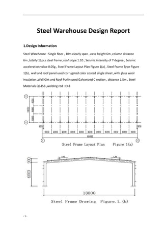
  • 1. - 1 - Steel Warehouse Design Report 1.Design Information Steel Warehouse : Single floor , 18m clearly span , eave height 6m ,column distance 6m ,totally 12pcs steel frame ,roof slope 1:10 , Seismic intensity of 7 degree , Seismic acceleration value 0.05g , Steel Frame Layout Plan Figure 1(a) , Steel Frame Type Figure 1(b) , wall and roof panel used corrugated color coated single sheet ,with glass wool insulation ,Wall Girt and Roof Purlin used Galvanized C section , distance 1.5m , Steel Materials Q345B ,welding rod : E43
  • 2. - 2 - 2.Loading Calculated (1) Loading Value : 1)Roof Dead Loading (Horizontal projected area) YX51-380-760 Corrugated single sheet 0.15 KN/m2 50mmGloass Wool Insulation 0.05 KN/m2 Aluminum Foil and wire mesh 0.02 KN/m2 Purlin and Bracing 0.10 KN/m2 Self-weight of Roof Beam 0.15 KN/m2 Hanging Equipments 0.20 KN/m2 Totally 0.67 KN/m2 2)Roof Live Loading Roof Live Loading Value : 0.50 KN/m2 。 Snow Loading : Snow PressureS0=0.45 KN/m2 。Double Slope Roof Roof Slope α=5°42′38,μr=1.0 , Snow Loading : Sk=μrS0=0.45 KN/m2 。 Compared live loading and snow loading used the bigger value : 0.50 KN/m2 Not consider the Dust Load . 3)Light Weight Wall and self-weight of column (including Column , wall-stud structures ) : 0.50 KN/m2 4)Wind Loading : According 《Technical Specification for Light-Weighted Steel Portal Frames》 CECS102: 2002 Basic Wind Pressure ω0=1.05×0.45 KN/m2 , Ground Roughness : B, Height variation factor of Wind Loading according《Building Structural Load Code》 (GB50009-2001), when height less than 10m, according 10m height value, μz=1.0. Wind Load Shape Factor μs : Windward Column and Roof are respectively+0.25 and-1.0, Leeward Column and Roof are respectively +0.55 and-0.65(CECS102:2002).
  • 3. - 3 - 3.The Load Standard Calculated Value of Each Part Roof Loading: Dead Loading Standard Values : 0.67×6=4.02KN/m Live Loading Standard Value : 0.50×6=3.00KN/m Column Loading : Dead Loading Standard Value : 0.5×6×6+4.02×9=54.18KN Live Loading Standard Value : 3.00×9=27.00KN Wind Loading Standard Value : Windward : Column qw1=0.47×6×0.25=0.71KN/m Rafter qw2=-0.47×6×1.0=-2.82KN/m Leeward : Column qw3=-0.47×6×0.55=-1.55KN/m Rafter qw4=-0.47×6×0.65=-1.83KN/m 4. Inner Force Analysis (1)Under Dead Loading λ=l/h=18/6=3 ψ=f/h=0.9/6=0.15 k=h/s=6/9.0449=0.6634 μ=3+k+ψ(3+ψ)=3+0.6634+0.15×(3+0.15)=4.1359 5289.0 1359.44 15.058 4 58        HA=HE=qlλΦ/8=4.02×18×3×0.5289/8=14.35KN MC=ql2 [1-(1+ψ) Φ]/8=4.02x182 [1-(1+0.15)×0.5289]=63.78KN·m MB=MD=-ql2 Φ/8=-4.02×182 ×0.5289/8=-86.11KN·m Inner Force of Steel Frame under dead loading as below figure
  • 5. - 5 - (2) Under Live Loading VA=VE=27.00KN HA=HE=3.00×18×3×0.5289/8=10.71KN MC=3.00×182 [1-(1+0.15)×0.5289]/8=47.60KN·m MB=MD=-3.00×182 ×0.5289/8=-64.26KN·m Inner Force of Steel Frame under live loading as below figure
  • 6. - 6 - (3) Under Wind Loading The wind load acting on the roof can be decomposed into the component force qx in the horizontal direction and the vertical component force qy. Calculated separately, and then superimposed. 1) The Rafter under the action of wind loading vertical component of forces (qw2y) on windward side 1322.0)15.058( 1359.416 1 )58( 16 1      KN l qa VE 35.6 182 982.2 2 22     VA=2.82×9-6.35=19.03KN HA=HE=qlλ Φ /4=2.82×18×3×0.1322/4=5.03KN MB=MD=5.03×6=30.18KN·m MC= ql2 [α 2 -(1+ψ ) Φ ]/4=2.82×182 ×[0.52 -1.15×0.1322]/4=22.38KN·m
  • 7. - 7 - Steel Frame Internal Force diagram under action of (qw2y) 2) The Rafter under the action of wind loading vertical component of forces (qw2y) on leeward side KN l qa VE 12.4 182 983.1 2 22     VA=1.83×9-4.12=12.35KN HA=HE=qlλ Φ /4=1.83×18×3×0.1322/4=3.27KN MB=MD=3.27×6=19.62KN·m MC= ql2 [α 2 -(1+ψ ) Φ ]/4=1.83×182 ×[0.52 -1.15×0.1322]/4=14.52KN·m Steel Frame Internal Force diagram under action of (qw2y)
  • 8. - 8 - 3) The Column under wind loading action qw1 on windward side α=1, 9803.0]16634.0)6634.015.02(6[ 1359.44 1 ])2(6[ 4 1 22      KK VA=-VB=-qh1 2 /2L=-0.71×62 /(2×18)=-0.71KN KN qh HA 22.3)9803.0 2 1 2( 2 1671.0 ) 2 2( 2     HE=0.71×6-3.22=1.04KN MD=1.04×6=6.24KN·m mKN qh MC    81.0)]9803.0)15.01(1[ 4 1671.0 ])1(1[ 4 2222   Steel Frame Internal Force diagram under action of (qw1) mKN qh MB    52.6)9803.02( 4 1671.0 )2( 4 2222 
  • 9. - 9 - 4) The Column under wind loading action qw3 on windward side VA=-VB=-qh1 2 /2L=-1.55×62 /(2×18)=-1.55KN KN qh HE 02.7)9803.0 2 1 2( 2 1655.1 ) 2 2( 2     HA=1.55×6-7.02=2.28KN MD=7.02×6-1.55×62 /2=14.22KN·m MB=2.28×6=13.68KN·m mKN qh MC    78.1)]9803.0)15.01(1[ 4 1655.1 ])1(1[ 4 2222   Steel Frame Internal Force diagram under action of (qw3)
  • 10. - 10 - 5) The Beam under wind loading action (qw2x )on windward side α=1,β=0 0202.0)15.0134( 1359.48 15.0    KNVV EA 91.0)9.062( 182 9.082.2     HA=2.82×0.9(1+0.0202)/2=1.29KN HE=2.82×0.9-1.29=1.25KN mKNMC    39.0]0202.015.15.015.0[ 2 69.082.2 MB=1.29×6=7.74KN·m MD=1.25×6=7.50KN·m
  • 11. - 11 - Steel Frame Internal Force diagram under action of (qw2x) 6) The Rafter under the action of wind loading vertical component of forces (qw4x) on leeward side KNVV EA 59.0)9.062( 182 9.083.1     HA=1.83×0.9(1+0.0202)/2=0.84KN HE=1.83×0.9-0.84=0.81KN mKNMC    26.0]0202.015.15.015.0[ 2 69.083.1 MB=0.81×6=4.86KN·m MD=0.84×6=5.04KN·m
  • 12. - 12 - Steel Frame Internal Force diagram under action of (qw4x) 7) The combined force of steel frame under wind load
  • 13. - 13 - 4.Internal force combination The frame structure is designed according to the ultimate capacity of the load capacity. According to the 《Building Structural Load Code》(GB50009-2001), the basic combination of load effect is used: γ 0S≤R. The safety grade of the structural components of this project is Grade 2, γ0 = 1.0. The design value of the load effect combination (S) is determined by taking the most unfavorable values from the following combination values : A. 1.2 × constant load standard value calculated load effect + 1.4 × live load standard value calculated load effect
  • 14. - 14 - B. 1.0 × constant load load value calculated by the load effect + 1.4 × wind load standard value calculated load effect C. 1.2 × constant load standard value calculated load effect + 1.4 × live load standard value calculated load effect + 0.6 × 1.4 wind load standard value calculated load effect D. 1.2 × constant load standard value calculated load effect + 1.4 × wind load standard value calculated load effect + 0.7 × 1.4 × live load standard value calculated load effect E. 1.35 × Constant load calculated by the load effect of + 0.7 × 1.4 × live load standard value calculated load effect The most unfavorable internal force combination of the calculated control section to take the bottom of the column, the top of the column, end beam and beam cross section, for the rigid beam, the cross section may be the most unfavorable internal force combination: Beam end section: (1) Mmax and the corresponding N, V; (2) Mmin and the corresponding N, V Beam cross section: (1) Mmax and the corresponding N, V; (2) Mmin and the corresponding N, V For the rigid column, the most unfavorable internal forces of the cross section are: (1) Mmax and the corresponding N, V; (2) Mmin and the corresponding N, V (3) Nmax and the corresponding ± Mmax, V; (4) Nmin and the corresponding ± Mmax, Internal Force Combination see below figure
  • 15. - 15 - Internal Force Combination of Steel Frame Figure 1 Section Internal Force Combination Loading combine mode Loading Combine portfolio M (KN·m) N (KN) V (KN) Column Top Column (B point) Mmax, N, V A 1.2×dead +1.4× live 193.30 81.22 -32.21(←) Mmin, N, V B 1.0×dead +1.4×wind -7.89 1.05 -1.67(←) Nmax ±Mmax、V A 1.2×dead+1.4×live 193.30 81.22 -32.21(←) Nmin ±Mmax、V B 1.0×dead+1.4×wind -7.89 1.05 -1.67(←) Bottom Column (A point) Mmax, N, V Mmin, N ,V Nmax ,±Mmax ,V A 1.2×dead+1.4×live 0 102.82 -32.21(→) Nmin ±Mmax ,V B 1.0×dead+1.4×wind 0 19.05 4.30(←) Beam Support (B point) Mmax N , V A 1.2×dead+1.4×live 193.30 39.89 77.60(↑) Mmini N ,V B 1.0×dead+1.4×wind -7.89 1.57 0.89(↑) Midspan (C Point) Mmax, N, V B 1.0×dead+1.4×wind -9.40 -2.03 0.60(↓) Mmin , N ,V A 1.2×dead+1.4×live -143.18 31.81 -3.21(↑)
  • 16.
  • 17. - 17 - 5.Steel Frame Design (1) Section design Column and Beam used welded H section Steel 450×200×8×12, Section properties: B=200mm,H=450mm,tw=8.0mm,tf=12.0mm,A=82.1cm2 Ix=28181cm4 ,Wx=1252cm3 ,ix=18.53cm Iy=1602cm4 ,Wx=160.2cm3 ,ix=4.42cm (2) Section Checking 1) Width-to-thickness ratio checking Flange Plate : 15235/f15896/12b/t y  Web Plate : 250235/f50225.356/824/th yw0  2) Beam Checking (1)The shearing calculation Max Shearing of Beam section Vmax=77.60KN Consider only with support stiffened plate 8.0562.0235/ 34.541 /0  y w s f th  fv=125N/mm2 Vu=hwtwfv=426×8×125=426000N=426.0KN Vmax=77.60KN<Vu,Ok (2) Bending moment, Shearing force, Pressure action checking together Checking and calculated the end of beam N=39.89KN,V=77.60KN,M=193.30KN·N Because V<0.5Vu,V=0.5Vu ,According to code , GB70017 . ))(( 22 2 2 1 1 A N fhA h h AM fff 
  • 18. - 18 - ) 8210 39890 215)(21912200 219 219 12200( 2  =220.90KN·m>M=193.30KN·m,M=Mf 10)1 5.0 ( 2     feu f u MM MM V V , OK (3) Overall stability checking N=39.89KN,M=193.30KN·m A.In-plane Beam Overall stability checking Calculated Length according beam length : lx=18090mm, λ x=lx/ix=18090/185.3=97.63<[λ ]=150,b type section ,ψ x=0.570 KN EA N e EX 0.1592 63.971.1 821010206 1.1 2 32 2 0 2 ' 0        ,β mx=1.0 ) 1592 89.39 570.01(101252 1030.1930.1 8210570.0 39890 )1( 3 6 ' 0 1 0        EX xe xmx ex N N W M A N    =165.15N/mm2 <f=215 N/mm2 , Ok B.Out-plane Beam Overall stability checking Calculated length according two purlin distance or flange bracing distance ,ly=3015mm。 As for uniform section γ =0,μ s=μ w=1 λ y=μ sl/iy0=3015/44.2=68.2,b type section , ψ y=0.762 6.0133.1) 4264.4 122.68 ( 101252 4268210 2.68 4320 2 32       by ψ b’=1.07-0.282/ψ by=0.821 975.0) N N (75.0 N N -1.0 2 ' EX0 ' EX0 t 22 3 6 10 /215/73.189 101252821.0 1030.193975.0 8210762.0 39890 mmNfmmN W M A N bre t ey          (4)《Design Code for Steel Structure》(GB50017-2003) Check the beam web to allow high thickness ratio. Beam end section:
  • 19. - 19 - 2 6 33 max min / 24.141 96.150 10.14686.4 1028181 2131030.193 8210 1089.39 mmN        94.1 max minmax 0       7.115 235 )2.265.048(25.53 0 0  yw ft h  ,OK Mid-span section : 2 6 33 max min / 35.104 09.112 22.10887.3 1028181 2131018.143 8210 1081.31 mmN        93.1 max minmax 0       3.115 235 )2.265.048(25.53 0 0  yw ft h  ,OK (5) Checking the area compressive bearing capacity under the concentrated load of purlin The purlin pass the concentrated load to the upper flange of the beam: F=(1.2×0.27×6+1.4×3.00)×3=18.43KN Lz=a+5hy+2hR=70+5×12+0=130mm 22 3 /215/72.17 1308 1043.180.1 mmNfmmN lt F zw c       Checking the reduce stress at the upper edge of the web Take the internal force at the end of the beam: M=193.30KN·m,N=39.89KN, V=77.60KN 2 4 3 1 /10.146213 1028181 1030.193 mmNy I M n     σc=17.72N/mm2 2 4 3 /61.34 81028181 419122001060.77 mmN It VS w     222222 61.343)89.3910.146(72.1772.17)89.3910.146(3   cc =130.65 N/mm2 <1.2f=258 N/mm2 ,OK
  • 20. - 20 - (3)Checking and calculated Column Shearing Check Max Shearing for column Vmax=32.21KN Consider only with supported stiffening rib 8.0562.0235/ 34.541 /0  y w s f th  fv=125N/mm2 Vu=hwtwfv=426×8×125=426000N=426.0KN Vmax=32.21KN<Vu , OK (2) Bending moment, Shearing force, Pressure action checking together Checking and calculated the end of beam N=81.22KN,V=32.21KN,M=193.30KN·N Because V<0.5Vu , V=0.5Vu, According to code GB70017 ))(( 22 2 2 1 1 A N fhA h h AM fff  ) 8210 81220 215)(21912200 219 219 12200( 2  =215.61KN·m>M=193.30KN·m,M=Mf 10)1 5.0 ( 2     feu f u MM MM V V , OK (3) Overall stability checking Max Internal Force of steel structure : N=102.82KN,M=193.30KN·m In-plane Steel Frame Overall stability checking Height of Column H=6000mm,Length of Rafter L=18090mm. linear rigidity of column K1=Ic1/h=28181×104 /6000=46968.3mm3 linear rigidity of beam K2=Ib0/(2ψS)=28181×104 /(2×9045)=15578.2mm3 K2/K1=0.332, The calculation length coefficient of the column μ=2.934 Calculated Length of Column lx=μh=17604mm λx=lx/ix=17604/185.3=95。0<[λ]=150,b type section , ψx=0.588
  • 21. - 21 - KN EA N e EX 4.1681 0.951.1 821010206 1.1 2 32 2 0 2 ' 0        ,βmx=1.0 ) 4.1681 82.102 588.01(101252 1030.1930.1 8210588.0 1082.102 )1( 3 63 ' 0 1 0         EX xe xmx ex N N W M A N    =181.45N/mm2 <f=215 N/mm2 , OK Out-plane Overall stability checking of Column Calculated length according two purlin distance or fly bracing distance ly=3000mm uniform section structure : γ=0,μs=μw=1 λy=μsl/iy0=3000/44.2=67.9,b type section , ψy=0.764 6.0138.1) 4264.4 129.67 ( 101252 4268210 9.67 4320 2 32       by ψ b’=1.07-0.282/ψ by=0.822 942.0) N N (75.0 N N -1.0 2 ' EX0 ' EX0 t 22 3 63 10 /215/32.193 101252822.0 1030.193942.0 8210764.0 1082.102 mmNfmmN W M A N bre t ey           (4)《Design Code for the Steel Structure》(GB50017-2003) Check the steel column to allow high thickness ratio Column Top Section: 2 6 33 max min / 21.136 99.155 10.14689.9 1028181 2131030.193 8210 1022.81 mmN        87.1 max minmax 0       0.111 235 )2.265.048(25.53 0 0  yw ft h  ,OK Column Bottom Section : 00  5.72 235 )255.016(25.53 0 0  yw ft h  , OK
  • 22. - 22 - 4.Check the lateral movement of the frame under wind load , μ Ic=Ib=28181cm4 ,ζt= Ic l/hIb=18000/6000=3.0 The equivalent horizontal force of the column is calculated by the following formula : H=0.67W=0.67×13.56=9.09KN W=(ω1+ω4)·h=(0.71+1.55)×6.0=13.56KN mmhmm EI Hh t c 40150/][1.14)32( 10281811020612 60001009.9 )2( 12 43 333      6.Detail Checking (1) Column and Beam Connected node 1) Bolt Strength Checking Column and beam node used 10.9Gr , connected by M22 frictional high-strength bolts, The contact surface of the component is sandblasted, Friction surface anti-slip coefficient μ = 0.45, each high-strength bolts of the pre-tension of 190KN, the transmission of internal force design value: N = 39.89KN, V = 77.60KN , M=193.30KN·m The tension of each bolt : KNKN n N y My N i 1521908.065.128 8 89.39 )16.0265.0(4 265.030.193 222 1 1      KNKN n N y My N i 1521908.070.75 8 89.39 )16.0265.0(4 16.030.193 222 2 2      Shear force of Bolt Group : KNVKNpnN f b V 60.776.615819045.019.09.0   , OK Outside row bolt of shear, tension force : 197.0 152 65.128 8/6.615 8/60.77  b t t b V V N N N N ,OK 2)End Plate thickness Checking End Plate thickness : t=21mm。 Calculated according double side support end plate :
  • 23. - 23 - mm feeebe Nee t wffw twf 9.20 205)]4640(40220046[ 1065.12846406 )](2[ 6 3       (3) Calculation of shear stress of beam , column joints 22 6 /125/52.106 10426426 1030.193 mmNfmmN tdd M v ccb     , OK (4)Web Plate strength calculated on bolt area Nt2=75.70KN<0.4P=0.4×190=76.0KN 22 3 /215/52.206 846 101904.04.0 mmNfmmN te P ww     ,OK (2)Mid-span Beam Node 1)Bolt Strength Checking Mid-span beam node used 10.9Gr , connected by M20 frictional high-strength bolts, The contact surface of the component is sandblasted, Friction surface anti-slip coefficient μ = 0.45, each high-strength bolts of the pre-tension of 155KN, the transmission of internal force design value: N=31.81KN,V=3.21KN,M=143.18KN·m
  • 24. - 24 - The tension of each bolt : KNKN n N y My N i 1241558.001.95 8 81.31 )16.0265.0(4 265.018.143 222 1 1      KNKN n N y My N i 1241558.079.55 8 81.31 )16.0265.0(4 16.018.143 222 2 2      Shear force of Bolt Group : KNVKNpnN f b V 21.32.502815545.019.09.0   , OK Outside row bolt of shear, tension force : 177.0 124 01.95 8/2.502 8/21.3  b t t b V V N N N N , OK 2)End Plate thickness checking End Plate thickness t=18mm Calculated according double side support end plate : mm feeebe Nee t wffw twf 8.17 205)]4640(40220046[ 1001.9546406 )](2[ 6 3       3) Web Plate strength calculated on bolt area Nt2=55.79KN<0.4P=0.4×155=62.0KN 22 3 /215/48.168 846 101554.04.0 mmNfmmN te P ww     , OK
  • 25. - 25 - Column Foot Design Column hinge connected with foundation, used plane type hinge connected column foot 1)Column foot internal force design value: Nmax=102.82KN , V=32.21KN; Nmin=19.05KN , V=4.30KN。 2)Because column foot shearing force smaller . Vmax=32.21KN<0.4Nmax=41.13KN,so the span no need the shear key, but calculated the column foot which arrange column bracing need the shear key. Nmin>0,Considering the column bracing pull up force, the bolt is still not bear the tension, so only consider the stability of column in the installation process o, according to
  • 26. - 26 - the requirements of the structure can be set to anchor bolt , used 4M24 bolt . 3)Column base plate area and thickness calculated A. Confirmed the column base plate area b=b0+2t+2c=200+2×12+2×(20~50)=264~324mm,b=300mm; h=h0+2t+2c=450+2×12+2×(20~50)=514~574mm,h=550mm; Checking the concrete under base plate design value of Axial compressive strength: Foundation used C20 Concrete , fc=9.6N/mm2 22 3 /6.9/62.0 550300 1082.102 mmNfmmN bh N cc      , OK B. Confirmed the thickness of Base plate According the Column Base Plate area that segmented by column web plate and flange plate calculate separately the maximum bending moment that base plate bearing, as for three plate support area : b2/b1=96/426=0.225<0.3 , Calculated by cantilever plate with length of b2 : mNaM  660814662.0 2 1 2 1 22 4 Cantilever Plate part : mNaM  7755062.0 2 1 2 1 22 4 Base Plate thickness : mmfMt 6.13215/66086/6 max  , t=20mm。 6.Other Structure Calculated (1) Fly Bracing Design Fly Bracing design according axle-center pressed structural member, axle center N calculated as following :
  • 27. - 27 - KNN fAf N y 16.121009.12 68.44cos60 21512200 235cos60 3       Connected bolt used normal C grade M12 Bolt , The calculation length of the corner supports the distance between the two ends of the bolt center : l0=633mm , used L50x4 , section properties: A=3.90cm2 ,Iu=14.69cm4 ,Wu=4.16cm3 , iu=1.94cm,iv=0.99cm λ u=l0/ iu=633/19.4=32.6<[λ ]=200, b type section , ψu=0.927 Strength design value that single side connected angle multiplied with the reduction factor , αy:λ=633/9.9=63.94, αy=0.6+0.0015λ=0.696 22 3 /215/0.48 390927.0696.0 1016.12 mmNfmmN A N uy       , OK (2) Purlin Design Basic Information Purlin used Galvanized C section steel, design according single span simple member, roof slope :1/10,purlin span6m ,set one row sag rod , purlin distance 1.5m ,steel materials Q235B. Loading and Internal force Consider the combination of dead load and roof live load as the control effect , Purlin linear load standard value: Pk=(0.27+0.5)×1.5=1.155KN/m Purlin linear load design value: Pk=(1.2×0.27+1.4×0.5)×1.5=1.536KN/m Px=Psinα=0.153KN/m,Py=Pcosα=1.528KN/m ; Design value of bending moment :
  • 28. - 28 - Mx=Pyl2 /8=1.528×62 /8=6.88KN·m My=Pxl2 /8=0.153×62 /32=0.17KN·m Section choose and section properties Choose : C180×70×20×2.2 Ix=374.90cm4 ,Wx=41.66cm3 ,ix=7.06cm; Iy=48.97cm4 ,Wymax=23.19cm3 ,Wymin=10.02cm3 ,iy=2.55cm,χ 0=2.11cm; Section stress calculated according gross section : 2 3 6 3 6 max 1 /48.172 1019.23 1017.0 1066.41 1088.6 mmN W M W M y y x x        (Press) 2 3 6 3 6 min 2 /18.148 1002.10 1017.0 1066.41 1088.6 mmN W M W M y y x x        (Press) 2 3 6 3 6 max 3 /82.157 1019.23 1017.0 1066.41 1088.6 mmN W M W M y y x x        (Pull) Stability Coefficient of the stress steel structure Web Plate Web Plate is the stiffened Plate,ψ=σmin/σmax=-157.82/172.48=-0.915>-1, k=7.8-6.29ψ+9.78ψ2 =21.743 Up Flange Plate Up flange plate is the biggest press act on the support edge of the stiffened plate ψ=σmin/σmax=148.18/172.48=0.859>-1, kc=5.89-11.59ψ+6.68ψ2 =0.863 The effective wide of the press plate Web Plate k=21.743,kc=0.863,b=180mm,c=70mm,t=2.2mm,σ1=172.48N/mm2 1.1952.1 863.0 743.21 180 70  ck k b c  Coefficient of constraint action between plate components k1=0.11+0.93/(ξ-0.05)2 =0.367 080.348.172/743.21367.0205/205 11   kk
  • 29. - 29 - Because ψ=σmin/σmax<0 , α=1.5 . bc=b/(1-ψ)=180/(1+0.915)=93.99mm b/t=180/2.2=81.82 18αρ=18×1.15×3.080=63.76,38αρ=38×1.15×3.080=134.60 So 18αρ<b/t<38αρ So the effective wide of section mmb tb b ce 62.8199.93)1.0 82.81 060.315.18.21 )1.0 / 8.21 (     be1=0.4be=0.4×81.62=32.65mm,be2=0.6be=0.6×81.62=48.97mm B. Top flange plate k=0.863 , kc=21.743, b=70mm, c=180mm , σ1=172.48N/mm2 1.1512.0 743.21 863.0 70 180  ck k b c  Coefficient of constraint action between plate components 398.1512.0/1/11  k 197.148.172/863.0398.1205/205 11   kk Because ψ=σmin/σmax>0,则 α=1.15-0.15ψ=1.15-0.15×0.859=1.021, bc=b=70mm,b/t=70/2.2=31.82 18αρ=18×1.021×1.197=22.00,38αρ=38×1.021×1.197=46.44 So 18αρ<b/t<38αρ So the effective wide of section mmb tb b ce 05.5770)1.0 82.31 197.1021.18.21 )1.0 / 8.21 (     be1=0.4be=0.4×57.0 5=22.82mm,be2=0.6be=0.6×57.05=34.23mm Purlin top flange plate and Web plate effective area
  • 30. - 30 - C. Lower Flange Plate Lower Flange Plate total cross section under tension and effective . D. Effective net-section modulus Top Flange deduct area the wide :70-57.05=12.95mmWeb Plate deduct area the wide : 93.99-81.62=12.37mm, and the calculated section of web plate with aφ 13 sag rod hole (35mm distance from top flange plate), hole position same as the deduct area, so the deduct area of web plate calculated accordingφ 13.see figure ,the effective net-section modulus : 34 224 10813.3 90 )3590(2.213902.295.121090.374 mmWenx    1.21 )2/2.21.21(2.213)1.2182.222/95.12(2.295.121097.48 224 max  enyW 34 10257.2 mm 1.2170 )2/2.21.21(2.213)1.2182.222/95.12(2.295.121097.48 224 max   enyW 34 10974.0 mm Wenx/Wx=0.915,Wenymax/Wymax=0.973,Wenymin/Wymin=0.972 Strength Calculated Consider roof could stop purlin lateral buckling and torsion: 22 4 6 4 6 max 1 /205/97.187 10257.2 1017.0 10813.3 1088.6 mmNfmmN We M W M ny y enx x        22 4 6 4 6 min 2 /205/99.162 10974.0 1017.0 10813.3 1088.6 mmNfmmN We M W M ny y enx x        Deflection Calculated mmlmmy 30200/][11.25 109.37410206 6000"38'425cos155.1 384 5 43 4       ,OK
  • 31. - 31 - Structural requirement λx=600/7.06=85.0<[λ]=200 , OK λy=300/2.55=117.6<[λ]=200 , OK (3) Wall Girt Design 1)Basic Information The Building project is single floor workshop, column distance 6m,eave height 6m ,above1.2m is corrugated single color sheet ,wall girt distance 1.5m, one row sag rod, steel materials Q235B 2)Loading Calculated Wall Girt used Galvanized C section steel :160x60x20x2.5mm ,wall weight : 0.22KN/m2 Wind Loading Basic wind loading: ω0=1.05×0.45=0.473KN/m2 , wind loading standard value calculated according CECS102:2002 ωk=μsμzω0,μs=-1.1(+1.0) When Calculated the wall girt no need calculated the weight of wall ,the wall sit on ground qx=1.2×0.07=0.084KN/m,qy=-1.1×0.473×1.5×1.4=-1.093KN/m 3)Internal force calculated Mx=0.084×62 /8=0.378KN·m , My=1.093×62 /8=4.919KN·m 4)Strength Calculated Wall Girt :C160×60×20×2.5mm Wxmax=19.47cm3 ,Wmin=8.66cm3 ,Wy=36.02cm3 ,Iy=288.13cm4 Reference wall purlin calculated result and project experience Wenx=0.9 Wx , Weny=0.9 Wy 22 3 6 3 6 /205/2.200 1002.369.0 10919.4 1066.89.0 10378.0 mmNfmmN W M W M eny y enx x        Under wind suction , the sag rod set at the internal of wall girt ,and arrange the inclined sag rod at the bottom of column ,and corrugated color sheet strong connected with
  • 32. - 32 - outside of wall girt ,so don’t need calculated the overall stability of wall girt. 5) Deflection calculated mmlmm 30200/][3.22 1013.28810206 60005.1473.01.1 384 5 43 4      , OK (4) Wind Column Design Basic information Wind Column height 6274mm ,distance 6m ,bearing loading including self-weight, wall girt weight ,and gable wall wind loading ,wind column hinge connected with foundation, design as compression-bending members. Wind Column used as simple member which support roof beam and foundation. Wind Pressure ω0=0.45KN/m2 , Ground roughness category B, Fly Bracing distance 3.0m,Wind Column used Q235B steel . Loading Calculated Wind Column used H section steel 300×200×6×10, self-weight:g1=44.6kg/m Wind Loading calculated according : CECS102:2002 ωk=μsμzω0 ,μs=-1.0(+1.0) ,ω0=1.05×0.45=0.473KN/m2 qz=1.2×(0.07×6×3+44.6×6.274×10-2 )=4.87KN qy=1.4×1.0×1.0×0.473×6=3.97KN/m Wind Column eccentricity under wall girt act :1.2×0.07×6×3×0.23=0.35KN·m Internal Force Calculated N=4.87KN , M=1/8×3.97×6.2742 +0.35=19.88KN·m Local Stability Checking of Steel Structure Width-to-thickness ratio of flange : b/t=96/10=9.6< yf/23513 2 3 63 max min / 49.30 21.32 101.634 1088.19 56800 1087.4 mmN W M A N x x        947.1 max minmax 0       ,因 1.6<α 0<2.0, l0=6274mm,λ x= l0/ ix=48.5<[λ ]=150
  • 33. - 33 - 7.46 6 280 5.91 235 )2.265.048( 0 0  wy t h f  , OK Strength Calculated Section Properties : A=56.8cm2 ,Ix=9511cm4,Wx=634.1cm3 ,ix=12.94cm, Iy=1334cm4 ,Wy=133.4cm3 ,iy=4.85cm 22 3 63 /215/7.30 101.63405.1 1088.19 56800 1087.4 mmNfmmN W M A N nxx x n        Checking the In-plane stability under bending moment λ=48.5 , b type section , ψx=0.863 KN EA NEX 1.4463 5.481.1 568010206 1.1 2 32 2 2 '        ,βmx=1.0 ) 1.4463 87.4 8.01(101.63405.1 1088.190.1 56800863.0 1087.4 )8.01( 3 63 '1         EX xx xmx x N N W M A N    =30.85N/mm2 <f=215 N/mm2 , OK Checking the Out-plane stability under bending moment Consider the fly bracing as Lateral Support of Out-plane wind column l0y=3000mm, λy= l0y/ iy=3000/48.5=61.9<[λ]=150,b type section , ψy=0.797 983.0 23544000 07.1 2  yy b f  ,η=1.0,βtx=1.0 3 63 1 101.634983.0 1088.190.10.1 56800797.0 1087.4       xb xtx y W M A N     =32.97N/mm2 <f=215 N/mm2 OK Deflection Calculated Wind Column under the action of horizontal wind loading could see as single span ,simply-supported beam and calculated horizontal deflection according below: mmlmm EI l x k 7.15400/][1.4 10951110206 627497.3 384 5 384 5 43 44       
  • 34. - 34 - Column Foot Design Because wind column bear small vertical load, so the base plate size used 400x300x20mm,anchor bolt used 2M20. (5)Column Bracing Design Column Bracing Layout as Below Column bracing is diagonal strut, used X cross rod bracing ,strut could also used as purlin, Column Bracing loading and internal force Bracing calculated figure as below : The wind loading at the top of gable wall(gable wall height 7.2m) μs=0.8+0.5=1.3 ,ω1=1.3×1.0×0.45×18×7.35/2=38.70KN
  • 35. - 35 - According half wall action on 1/3 wind loading consider the loading standard value: Fwk=1/3×1/2×38.70=6.45KN Node loading design value : Fw=1.4×6.45=9.03KN diagonal strut tension design value N=9.03/cos43.9191°=12.54KN diagonal strut section design and strength checking used φ12 rod , A=113.0mm2 Strength Calculated :N/A=12.54×103 /113.0=111.0N/mm2 <f= 215N/mm2 Ridge Calculated : tension rod no need consider the required of slenderness ratio But Consider the structural used φ16 rod (6)Roof Horizontal Bracing Roof Bracing Layout Plan Purlin distance 1.5m ,horizontal bracing :3m Roof Bracing loading and internal force Roof bracing used tension rod, bracing calculated as figure. On gable wall side wind loading shape coefficient μs=1.0.
  • 36. - 36 - Node Loading Standard Value: Fwk=0.45×1.0×1.0×3.0×7.35/2=4.96KN ; Node Loading Design Value : Fw=4.96×1.4=6.94KN; Diagonal strut tension design value : N=2.5×6.94/cos29.0546°=19.85KN Diagonal strut section design and strength calculated Diagonal strut used :φ12 rod , A=113.0mm2 Strength Calculated :N/A=19.85×103 /113.0=175.7N/mm2 <f= 215N/mm2 Ridge Calculated: tension rod no need consider the required of slenderness ratio But Consider the structural used φ16 rod (7)Canopy Design (1) Basic Information Canopy total length 6000mm,overhang type, overhang length 1500,used Q235B steel, Purlin used C180×70×20×2.2mm (2) Loading Calculated 1)Dead Loading Corrugated single color sheet 0.15KN/m2 Purlin, Canopy Beam and other structures 0.10 KN/m2 Total 0.25 KN/m2 Canopy Beam linear load standard value : 0.25×3=0.75 KN/m2 2)Live Loading Along the wide of sheet each 1.0m choose one construction and repair loading ,each concentrated load 1.0Kn, act area at the outside edge of canopy, so the live loading on canopy is 3.5Kn. 3)Wind Loading Wind loading shape coefficient of canopy :μs=2.0 ,ω0=0.45KN/m2 ωk=μsμzω0=2.0×1.0×0.45=0.90 KN/m2 Convert the loading standard value act on canopy beam: 0.90×3=2.70KN/m (3)Internal calculated and section design
  • 37. - 37 - Canopy Beam calculated as figure g+q=1.2×0.75+1.4×2.70=4.68KN/m P=1.4×3.5=4.9KN Most critical section on the root of beam : M=12.62KN·m , V=11.92KN Canopy Beam used variable cross-section built up H beam (200~100)×150×6×8 Beam root section properties : A=3504m2 ,Ix=6×1843 /12+8×150×962 ×2=2523×104 mm4 , Wx=2523×104 /96=26.3×104 mm3 22 3 0 /125/8.10 1846 1092.11 mmNfmmN th V v w     , OK 22 4 6 /215/7.45 103.2605.1 1062.12 mmNfmmN W M nxx x      , OK Canopy beam connected with column used 4M20 normal C grade bolt -END-