11-Introduction to Axially Compression Members (Steel Structural Design & Prof. Shehab Mourad)
•
7 likes•1,136 views

11-Introduction to Axially Compression Members (Steel Structural Design & Prof. Shehab Mourad)

Recommended
More Related Content
What's hot
What's hot (20)
Similar to 11-Introduction to Axially Compression Members (Steel Structural Design & Prof. Shehab Mourad)
Similar to 11-Introduction to Axially Compression Members (Steel Structural Design & Prof. Shehab Mourad) (20)
More from Hossam Shafiq II
More from Hossam Shafiq II (20)
Recently uploaded
Recently uploaded (20)
11-Introduction to Axially Compression Members (Steel Structural Design & Prof. Shehab Mourad)
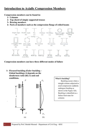
- 1. 1 Prepared by Prof. Shehab Mourad – Department of Civil Eng. - KSU Introduction to Axially Compression Members Compression members can be found in: 1- Columns 2- Top chord of simply supported trusses 3- Bracing members 4- Parts of members such as the compression flange of rolled beams Compression members can have three different modes of failure . 1- Flexural buckling (Euler buckling – Global buckling), it depends on the slenderness ratio (KL/r) and end conditions. L (a) P P (b) Pcr Pcr What is buckling? Buckling occurs when a straight column subjected to axial compression suddenly undergoes bending as shown in the Figure 1(b). Buckling is identified as a failure limit-state for columns
- 2. 2 Prepared by Prof. Shehab Mourad – Department of Civil Eng. - KSU 2- Local buckling occurs when some part of cross section are so thin that can buckle locally in compression before flexural buckling occur.
- 3. 3 Prepared by Prof. Shehab Mourad – Department of Civil Eng. - KSU 3- Torsional buckling may occur in columns having certain cross sections, where the shear center does not coincide with the center of gravity. These columns failed by twisting or combination of torsion and flexural buckling yo c.g. s.c. s.c c.g. yo xo yo s.c
- 4. 4 Prepared by Prof. Shehab Mourad – Department of Civil Eng. - KSU Euler Formula For a pined-pined column with length (L) and cross section (A) and has a moment of Inertia (I) with a modulus of Elastically (E), The buckling load is given by Euler formula (PE) And the buckling stress (critical Stress) , Fcr is given by: In general, for different end conditions, the buckling length will be equal to KL where K, depends on the end conditions and Fcr , is given by Fcr = π2 E , where KL/r is called slenderness ratio of the column (KL/r)2 Fcr = PE = π2 E (I/A) = π2 E A L2 (L/r)2 PE = π2 E I L2
- 5. 5 Prepared by Prof. Shehab Mourad – Department of Civil Eng. - KSU Column Formulas ( Short, Intermediate and long column) (Φ = 0.85 for compression members) Ag = gross area of cross section even there are holes for bolts (elastic buckling) , long columns (for λc > 1.5) Fcr = 0.877 π2 E = 0.877 Fy where λc = KL/r √ Fy / E (KL/r)2 λc 2 π ( Inelastic buckling), short and intermediate columns For λc ≤ 1.5 Fcr = (0.658 ) Fy Φ Pn = 0.85 Ag Fcr λc 2 x y For wide flange sections, x is the major axis and y is the minor axis. Major axis means axis of greater moment of inertia (Ix > Iy)
- 6. 6 Prepared by Prof. Shehab Mourad – Department of Civil Eng. - KSU Local buckling of the cross section elements Local buckling of flanges and webs of column cross section can occur before the member reaches its buckling load. LRFD specifications provide limiting values for the width-thickness ratios of the individual elements of compression members as follows;
- 7. 7 Prepared by Prof. Shehab Mourad – Department of Civil Eng. - KSU Limiting width-thickness ratio for compression elements, local buckling will occur if those limits are exceeded 1- Unstiffened elements: - Single angle and double angles λ r = b/t = 0.45 √ E / Fy - Flanges of W-shapes and channels; λ r = b/t = 0.56 √ E / Fy in pure compression - Stem of tees; λ r = d/t = 0.75 √ E / Fy 2- Stiffened elements: - Flanges of rectangular box and hollow structural sections λ r = b/t = 1.40 √ E / Fy - All other elements uniformly compressed and supported along two edges as web of W-shapes λ r = b/t = 1.49√ E / Fy Effect of local buckling in the compression strength If the limits of b/t > λ r , a reduction factor Q is applied to the yield strength, where ; Q = Qs . Qa Qa: reduction factor for stiffened elements as webs Qs : reduction factor for unstiffened elements as angle legs and W-shape flanges
- 8. 8 Prepared by Prof. Shehab Mourad – Department of Civil Eng. - KSU Note that ; Qs = 1.0 if the cross section is composed of only stiffened elements as hollow sections Qa = 1.0 if the cross section is composed of only unstiffened elements as angles and Tees For sections that are composed of both stiffened and unstiffened elements such as W-shapes and channels, Q = Qs . Qa For Unstiffened compressed elements a) For single angle 0.45√ E / Fy < b/t < 0.91 √ E / Fy b/t ≥ 0.91 √ E / Fy b) For flanges of W-shapes and channels 0.56√ E / Fy < b/t < 1.03 √ E / Fy b/t ≥ 1.03 √ E / Fy c) For stems in tees 0.75√ E / Fy < d /t < 1.03 √ E / Fy b/t ≥ 1.03 √ E / Fy Qs = 0.534 E Fy (b/t)2 Qs = 1.34 – 0.76 (b/t) √ Fy / E Qs = 1.415 – 0.74 (b/t) √ Fy / E Qs = 0.69 E Fy (b/t)2 Qs = 1.908 – 1.22 (d/t) √ Fy / E Qs = 0.69 E Fy (d/t)2
- 9. 9 Prepared by Prof. Shehab Mourad – Department of Civil Eng. - KSU For Stiffened Compression elements If h/tw ≥ 1.49 √ E / Fy be = 1.91 * tw * − f E thf E w * )/( 34.0 1* < hw f : computed elastic compression stress in the stiffened element based on design properties Qa = A effectiveArea.Σ = [ ] A tbA w** − Factored Strength of Column If Qc*λ < 1.5 Fcr = Q (0.658) * Fy If Qc*λ > 1.5 Fcr = 0.877 * Fy λc2 where λc = KL/r √ Fy / E π be/2 be/2 b* hw Q λc2 Φ Pn = 0.85 Ag Fcr