1. Load Estimating for Air Conditioning using Computer Software Approach
Load Estimating for Air Conditioning using Computer Software
Approach
B. Kareem
Department of Mechanical Engineering
Federal University of Technology, Akure, Nigeria
Email: karbil2002@yahoo.com.
Abstract
Traditionally, load estimating for air
conditioning systems is done either by
manual calculation or judgmental estimation
based on experience of the air conditioning
practitioner. While manual calculation is
laborious, estimate based on judgment is
liable to error due to gigantic, complex and
dynamic nature of present day architectural
designs.
Load estimating through computer
automation is likely to make a positive
impact in the dynamic nature of air
conditioning applications. This study
develops computer software in Basic
computer programming language named
Computer Aided Load Estimating for Air
Conditioning- CALAC-2004 to handle
simple, intricate and dynamic nature of load
estimate for air conditioning in developing
country. Application of the developed
software to FUTA Library showed that a
total load of 806.26kW was estimated for the
three floors it contained. With this load it
will be uneconomical and ineffective the use
of window or split type of air-conditioner (a-
c), instead, central a-c unit is preferable in
the FUTA Library.
Keywords: CALAC-2004, Computer
Automation, Load Estimating, Air-
Conditioning, FUTA Library.
1. Introduction
Air-conditioning is utilised to supply a
controlled atmosphere to public buildings
such as offices, halls, homes, and industries
for the comfort of human being or animals or
for the proper performance of some
industrial processes. Full air-conditioning
implies that the purity, movement,
temperature and relative humidity of the air
be controlled within the limits imposed by
the design specification.
In tropical and subtropical countries,
cooling by means of air-conditioning is a
necessary feature of modern development as
the new and emerging industries and
households need it to retain reliability of
some industrial and home based appliances.
Air-conditioning system is designed with
ability to subdue most common heat loads
such as sensible and latent heat (Adeyemo,
2000; James, 1995). The ability of air-
conditioning system to maintain condition of
comfort or condition required by a product or
process has made its use inevitable for
sustainable development especially in
developing countries. The system will finds
application in other areas of endeavours as
diverse is automobile, pharmaceutical
industry, cocoa processing industry and
textile industry.
For any air conditioning system to
perform satisfactorily, equipment of the
proper capacity must be selected based on
International Journal of The Computer, the Internet and Management Vol.16. N.o.2 (May-August, 2008) pp 35-43
35
2. B. Kareem
the instantaneous peak load requirements.
The type of control used is dictated by the
conditions to be maintained during peak and
partial load. Undersized equipment will not
provide the required conditions while a
greatly oversized one will lead to operating
problems such as “hunting”. However, actual
peak or partial load cannot be measured in
space, instead, the loads are estimated. The
load estimate establishes the amount of air
required to cope with the cooling load as
well as the piping requirement for water or
refrigerants (Trane, 1999; William and
Williams, 1995; Jones, 1989). Before the
load is estimated, it is important that a
comparative survey be made to ensure
accurate evaluation of the load components
(latent and sensible) especially in the areas of
mechanical, architectural and structural
drawing or field sketches. The factors that
must be critically looked into during load
estimation process include orientation of
building (location), space used, dimensions,
column and beams, construction materials,
surrounding conditions, windows, doors,
people, lighting, ventilation, thermal storage
and floor (ASHARE, 2001).
Load estimating in air-conditioning
system design has been carried out manually
in many quarters in developing country such
as Nigeria. A lot of time and energy are
wasted when estimating the cooling loads in
complex and intricate buildings of modern
time. Automation through computer
application sounds reasonable to replace
tedious and time consuming manual
methods. To achieve this computer
automation, software is developed using
“qbasic” programming language tool. Qbasic
is used in this work because of its simplicity
and easily understandable by professionals.
Besides, it is a versatile tool that has ability
to handle large and complex problem of this
kind.
Many research works exist in area of
load estimating in air-conditioning but less
attention is being paid to the computer
automation of the process. The only area
found of computer involvement is in ducts
design (Turtle and Bailey, 1985; CAC, 1985;
CGC, 1999). Duct design is done after
cooling loads have been estimated. This
study develops computer software named
Computer Aided Load Estimating in Air-
Conditioning (CALAC-2004). The
developed computer software in “qbasic” has
ability to estimate cooling load in complex
and simple building which assists in
selecting appropriate equipment, design air
distribution system and other piping systems.
2. Materials and Methods
Load components in air-conditioning
system for a selected building are identified.
Accurate load estimates are important pre-
requisite of a good air-conditioning system
design. Ultimate system performance also
depends on the proper system selection
based on reasonable load estimate. The air-
conditioning load estimate is based on heat
coming into space from outdoors on a design
day when the dry and wet bulb are peaking
simultaneously and also a heat generated
within the occupied space. However,
experience and experiments have shown that
all of the loads rarely peak at the same time.
To be realistic, various diversity factors must
be applied to some of the load components.
A cooling load calculation determines
the total sensible cooling load due to heat
gain through structural components (walls,
floors and ceiling for example), windows
(infiltration and ventilation), and occupancy
(size of people). The latent portion of the
cooling load is evaluated separately as a
single zone. The entire structure is
considered in term of equipment selection
and system design on a room –by-room
bases. Based on this arrangement, amount of
conditioned air required by each room is
estimated based on ASHRAE (2001). Indoor
36
3. Load Estimating for Air Conditioning using Computer Software Approach
design condition of 240
C db (dry bulb) with
maximum relative humidity of 50%RH is
currently accepted as satisfactory indoor
design criteria.
Areas of the building perimeter with
exterior glass and wall exposures have an
air-conditioning load that includes solar gain
through glass and wall. This may include the
roof gain. External loads include sun rays
entering window, strike the wall and roof;
and outdoor air (for ventilation). ASHRAE
(2001) provides appropriate storage factors
to be used with peak solar heat gain as well
as equivalent temperature differences for
sunlit and shaded walls and roofs. The
outdoor air imposes a cooling and
dehumidifying load on the apparatus because
the heat and/or moisture content must be
removed. Some air-conditioning system
provides a system that permit outdoor air by-
passing the cooling surface. The by-passed
outdoor air becomes a load within the
conditioned space directly. This has made
load imposed by ventilation air to be
estimated in two parts.
The internal load, or heat generated
within the space, depends on the
characteristics of the application. Proper
diversity and usage factor is applied to
internal loads. Similar to solar heat gain,
which is partially stored and reduced the load
imposed on the air-conditioning equipment.
Internal heat gain includes, people (through
metabolism), lights, appliances and electric
calculators. The amount of heat generated
from people depends on surrounding
temperature and on the activity level of the
person. Some of the heat generated from
light is radiant and partially stored.
Therefore, application of storage and
diversity in usage factors is considered in
estimating the load from light. Application of
usage and diversity factor is also considered
for electrical appliances and machines as
both are not used simultaneously in most
cases.
The sensible cooling load due to heat
from the walls, floors and ceiling of each
room is estimated using appropriate cooling
load temperature deference (CTLD) and U-
factors for summer condition. For ceiling
under natural vented attics or beneath vented
flat roofs, the combined U-factor for the
roof, vented space and ceiling is used. The
mass of the walls is a variable and is
important in estimating energy used. Daily
rang (outdoor temperature swing on a
design) day significantly affects the
equivalent temperature difference. ASHRAE
lists daily temperature ranges and classified
it as high, medium and low.
Direct application of procedures for
estimating load due to heat gain for flat glass
results in unrealistic high cooling loads for
non-residential and residential installations.
Therefore, window glass load factors (GLF)
are modified for non-residential cooling load
estimation including solar heat load. In this
application, the area of window is multiplied
by the appropriate GLF. The effect of
permanent outside shaving devices is
considered separately in determining the
cooling load. Shaded glass is considered the
same as north-facing glass. The shade line
factor (SLF), the ratio of the distance a
shadow false beneath the edge of an
overhang to the width of the overhang. The
overhang is assumed to be at the top of the
windows and the shade line equals the SLF
times the overhang width. The shaded and
sunlit glass areas are computed separately.
Roof overhangs do not effectively protect
north-east and northwest- facing windows in
most cases, therefore, they are considered
shaded. If the anticipated infiltration is less
than 0.5ACH (air discharge), when positive
means of introducing outdoor air are
available, controls either manual or
automatic is necessary and an energy
recovery device is necessary. Sensible heat
gain per sedentary occupant is assumed to be
67W. The number of occupants is not
International Journal of The Computer, the Internet and Management Vol.16. N.o.2 (May-August, 2008) pp 35-43
37
4. B. Kareem
overestimated to prevent gross over-sizing.
Heat loss or gain to the ducts or pipes are
included in the estimated load in case of air
distribution system outside the conditioned
space, that is, in attics, crawl spaces or other
unconditioned space.
Federal University of Technology,
Akure (FUTA) newly built library is facing
north at latitude 7.250
N. Roof construction of
library building is made of conventional
roof-attic-ceiling combination, vented to
remove moisture with 150mm of fibrous
insulation U= 0.62W/m2
K. The floor
construction is 100mm concrete slab on
grade. The windows are made of clear-
double glass, 3mm thick, in and out, with
closed medium colour venetian blinds. The
window glass has a 600mm overhang at the
top. Doors are made of solid core flush with
all-glass storm doors (U= 1.87W/m2
K).
Temperature of 340
C dry bulb (db) with a
humidity ratio of 0.0136kg vapour/kg dry air
and 280
C wet bulb. Indoor design condition
is made of temperature of 240
C db and
50%RH. The occupants are assumed based
on the available space. The electrical
consultants gave the values of appliances and
light in Watts according to the library design
plan. Air-conditioning system designed in
the plan is either window or split type based.
The formulae used in estimating the sensible,
latent and total cooling loads for non-
residential building with their respective
conditions are summarised in Table 1. The
meaning of indicated symbols/abbreviations
are: q, sensible cooling load (W); Q,
volumetric airflow rate (1/s); Dt, design
temperature difference between outside and
inside air (K); ACH, air change per hour
(1/h); A, area of applicable surface (m2
);U,
U-factors for appropriate construction
(W/m2
K); CTLD, cooling load temperature
difference (K); and GLF, glass load factor
(W/ m2
).
Table 1: Summary of Procedures for Non-Residential Cooling Load Estimation
Load source Equation for load q estimation
Glass and window areas GLF.A
Doors Ud.A.CTLD
Above-grade exterior wall Uw.A.CTLD
Partitions unconditioned
space
Up.A.Dt
Ceilings and roofs Ur.A.CTLD
Exposed floors Ur.A.CTLD
Infiltration 1.2QDt
Internal loads-
people,appliances,light
Plan 67W per person
Total load Total cooling load = load factor LF x
Sum of individual sensible cooling load
components
Source: ASHRAE, 2001
38
5. Load Estimating for Air Conditioning using Computer Software Approach
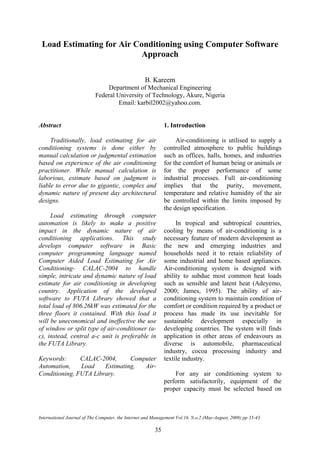
The estimates are made easy through the
use of computer software named Computer
Aided Load Estimating for Air-conditioning
(CALAC-2004) developed in “qbasic:”. The
flowchart developed for the CALAC-2004 is
shown in Figure 1. The mode of operation of
the flowchart/software is summarised using
the following algorithm:
10 Input parameters
20 If glass and window load goto 100
else30
30 If doors load goto 100 else 40
40 If exterior wall load goto 100 else 50
50 If partitioned unconditioned space
load goto100 else 60
60 If ceiling and roof loadgoto 100 else
70
70 If exposed floor load goto 100 else 80
80 If infiltration load goto 100 else 90
90 If internal load goto 100 else 20
100 If modification in parameters exist
goto 10 else goto 110
110 Calculate the following load statistics,
then goto 120:
Glass and windows
qg = (GLF)A
Doors
qd =UdA(CTLD)
Exterior walls
qw =UwA(CTLD)
Partition unconditioned
qp =UpA(Dt)
Ceiling and roof
qr =UrA(CTLD)
Exposed floor
qr =UrA(CTLD)
Infiltration
qi= 1.2 Q(Dt)
Internal
ql= 67W per person
120 Calculate the cooling load per room
CL= LF(load factor).∑q (or SL)
130 If room(s) left goto 10 else 140
140 Calculate the total cooling load
TCL =∑CL
150 Calculate the total latent load
TLL = TCL- TSL
The U-values, that is, Coefficient of
transmission Ur for roof, Uw for wall Up for
partitions and Uv for doors were
obtained/evaluated as 0.62W/m2
K,
1.61W/m2
K, 1.47W/m2
K and 1.87W/m2
K
respectively from ASHRAE (2001). Latent
load factor of 1.15 is used. Areas of the
respective system are obtained from the
measurement of lengths, breadth or height as
explained before. Table 2 gives, the sensible,
latent and the total loads obtained for each
room of the new FUTA library complex as
indicated appropriately. The summary of the
result for the three floors are given in Table
3. The result in Table 3 is helpful in the
choice of required sizes or equipment based
on the load capacity as stated in Carrier
General Catalogue (CAC, 1985; Trane,
1999)
3. Results and Discussion
The results obtained for new FUTA
library using CALAC-2004 showed that
loads estimated - sensible, latent, and total
load varied from one room to the other. The
highest load estimates of 63.59kW, 89.13kW
and 93.27kW were obtained for open-access
collection/reading rooms in the ground,
middle and last floors respectively. This
suggests that alternative method of cooling
using central air-conditioning system will be
economical in three reading rooms of the
three floors because cooling loads estimated
in these zones are beyond what a split or
window type of air-conditioning, currently in
use, can carry. The window and split types of
air-conditioning system can carry load of
2.72 kW, 2.35kW and 2.42kW and 2.45kW,
which are smallest loads estimated for
secretary office (last floor), secretary office
(middle floor) and secretary office/waiting
room (ground floor) respectively.
International Journal of The Computer, the Internet and Management Vol.16. N.o.2 (May-August, 2008) pp 35-43
39
6. B. Kareem
40
Start
Input load
parameters
G&W?
D?
C&R?
EF?
IL?
IN?
PUS?
EW?
Est. G&W
Est D
Est IN
Est IL
Est EF
Est C&R
Est PUS
Est EW
Any
modification?
Est Sensible
load/room
Est Latent
load/room
Est Total
load/room
More room?
Est total
load/building
G&W, glass and window load
D, door load
EW, exterior wall load
PUS, Partition unconditioned
space load
C&R, ceiling and roof load
EF, exposed floor
IL, internal load
IN, infiltration
Est., estimate
Stop
Figure.1 Flowchart for the load estimating software
7. Load Estimating for Air Conditioning using Computer Software Approach
Generally, it will be more meaningful
and economical to have a library design with
the plan of installing a central a-c system that
will take care of all the cooling loads at once.
Efforts in this direction would greatly save
space and economic in maintenance. The
only disadvantage of this arrangement is the
total discomfort it may cause in the case of
failure of the central a-c system.
Table 1: Summary of Procedures for Non-Residential Cooling Load Estimation
Load source Equation for load q estimation
Glass and window areas GLF.A
Doors Ud.A.CTLD
Above-grade exterior wall Uw.A.CTLD
Partitions unconditioned space Up.A.Dt
Ceilings and roofs Ur.A.CTLD
Exposed floors Ur.A.CTLD
Infiltration 1.2QDt
Internal loads-people,appliances,light Plan 67W per person
Total load Total cooling load = load factor LF x Sum of
individual sensible cooling load components
Source: ASHRAE, 2001
Table 2a: Total Cooling Load for Ground Floor
Conditioned space Sensible
load (kW)
Latent load
(kW)
Total load
(kW)
Secretary’s office 2.13 0.32 2.45
Dept. Univ. Lib. Tech. 5.35 0.82 6.15
Reference room 20.25 3.04 23.29
Reference library 3.84 0.58 4.42
Non-controlled reading/catalogue 22.58 3.39 25.97
Subject librarian 6.05 0.90 6.95
Optic workstation 17.18 2.60 20.48
Circulation library 4.23 0.63 4.86
Bindery 4.02 0.61 4.63
Bindery office 3.77 0.57 4.34
Processing lab. 2.83 0.42 3.25
Wet room 2.13 0.32 2.45
Photo studio 4.07 0.62 4.69
Staff room 4.30 0.65 4.95
Kitchen 6.39 0.96 7.35
Acquisition section 3.56 0.54 4.10
Acquisition librarian 3.29 0.49 3.78
Automation librarian 3.29 0.49 3.78
Automation unit 7.17 1.08 8.25
Open access collection/ reading room 55.29 8.30 63.59
Newspaper/CNN reading room 8.88 1.33 10.21
Cataloguing section 4.91 0.74 5.65
International Journal of The Computer, the Internet and Management Vol.16. N.o.2 (May-August, 2008) pp 35-43
41
8. B. Kareem
Table 2b: Total Cooling Load for Middle Floor (First floor)
Conditioned space Sensible
load (kW)
Latent load
(kW)
Total load
(kW)
Work room (1) 2.28 0.34 2.62
Serial librarian 2.28 0.34 2.62
Secretary’s office 2.03 0.32 2.35
Dept. Univ. Lib. readers 3.84 0.58 4.42
Audio room 6.34 0.95 7.29
Reference room 20.25 3.04 23.29
Work room (2) 4.21 0.63 4.84
Artist studio 5.37 0.80 6.17
Open access collection/ reading room (1) 77.51 11.62 89.13
Subject librarian 6.30 0.95 7.25
Open access collection/ reading room (2) 71.43 10.71 82.14
Postgraduate research room 52.15 7.82 59.97
Table 2c: Total Cooling Load for Last Floor (Second floor)
Conditioned space Sensible
load (kW)
Latent load
(kW)
Total load
(kW)
Work room (1) 2.28 0.34 2.62
Serial librarian 2.28 0.34 2.62
Secretary’s office 2.03 0.32 2.35
Dept. Univ. Lib. readers 3.84 0.58 4.42
Audio room 6.34 0.95 7.29
Reference room 20.25 3.04 23.29
Work room (2) 4.21 0.63 4.84
Artist studio 5.37 0.80 6.17
Open access collection/ reading room (1) 77.51 11.62 89.13
Subject librarian 6.30 0.95 7.25
Open access collection/ reading room (2) 71.43 10.71 82.14
Postgraduate research room 52.15 7.82 59.97
Table 3: Summary of the Cooling Load Results
Floor Load (kW) Total sensible load (kW) Total latent load (heat)
(kW)
Ground floor 230.82 200.71 30.11
Middle floor 281.60 244.47 36.73
Last floor 293.84 255.51 38.33
Total 806.26 709.09 105.17
42
9. Load Estimating for Air Conditioning using Computer Software Approach
4. Conclusion
The study has developed a system
framework that estimate cooling loads for
air-conditioning system for both sample and
complex non-residential buildings. The
system developed was able to estimate
various loads in buildings which are sensible,
latent and total load. The load computation
was computer automated for easy application
in industries. The computer software
developed for the load estimation named
Computer Aided Load Estimating for Air-
Conducting-CALAC-2004 in “qbasic” ran
effectively in windows and was able to
estimate cooling loads for different rooms in
the ground, middle and last floors based on
the input parameters related to loads through
windows, doors, floors, partition, infiltration
and others mentioned previously based on
ASHRAE (2001).
When data collected from the FUTA
new library was analyzed and used as input
into the CALAC-2004, one concludes from
the results obtained that alternative method
of using central air-conditioning system is
necessary for effective cooling of loads
generated in the library complex. The use of
central a-c unit will reduce space and at the
same time promote effectiveness in cooling
ability. Demerit of it in the area of non-
selectivity in cooling action and at the time
of failure since the system is centrally
controlled.
References
Adeyemo, T., (2000). Refrigeration and
the Air Conditioning, Greenline
Publishers, Nigeria. 113pp.
ASHRAE, (2001). ASHRAE Fundamentals
Handbook, American Society of
Heating, Air-Conditioning and
Refrigeration Publishing Service.
CAC, (1985). Handbook of Air-Conditioning
Systems Design, Carrier Air-
Conditioning Corporation, USA.
CGC, (1999). Carrier General Catalogue,
British Standard Inc.
James, C.W., (1995). Air Conditioning
Technology, Wellington Publishers,
USA. 413pp.
Jones, W. P., (1989). Air Conditioning
Engineering, Edward Arnold
Publishing Company. 327pp.
Trane, H. J., (1999). General Catalogue,
America Standard Inc.
Turtle and Bailey, (1985). Air-conditioning
Technology Manual, Turtle and Bailey
Manufacturing Company.
William, C. W. and Williams, M. J., (1995).
Refrigeration and Air-Conditioning
Technology, Relmer Publisher, USA.
321pp.
---
International Journal of The Computer, the Internet and Management Vol.16. N.o.2 (May-August, 2008) pp 35-43
43