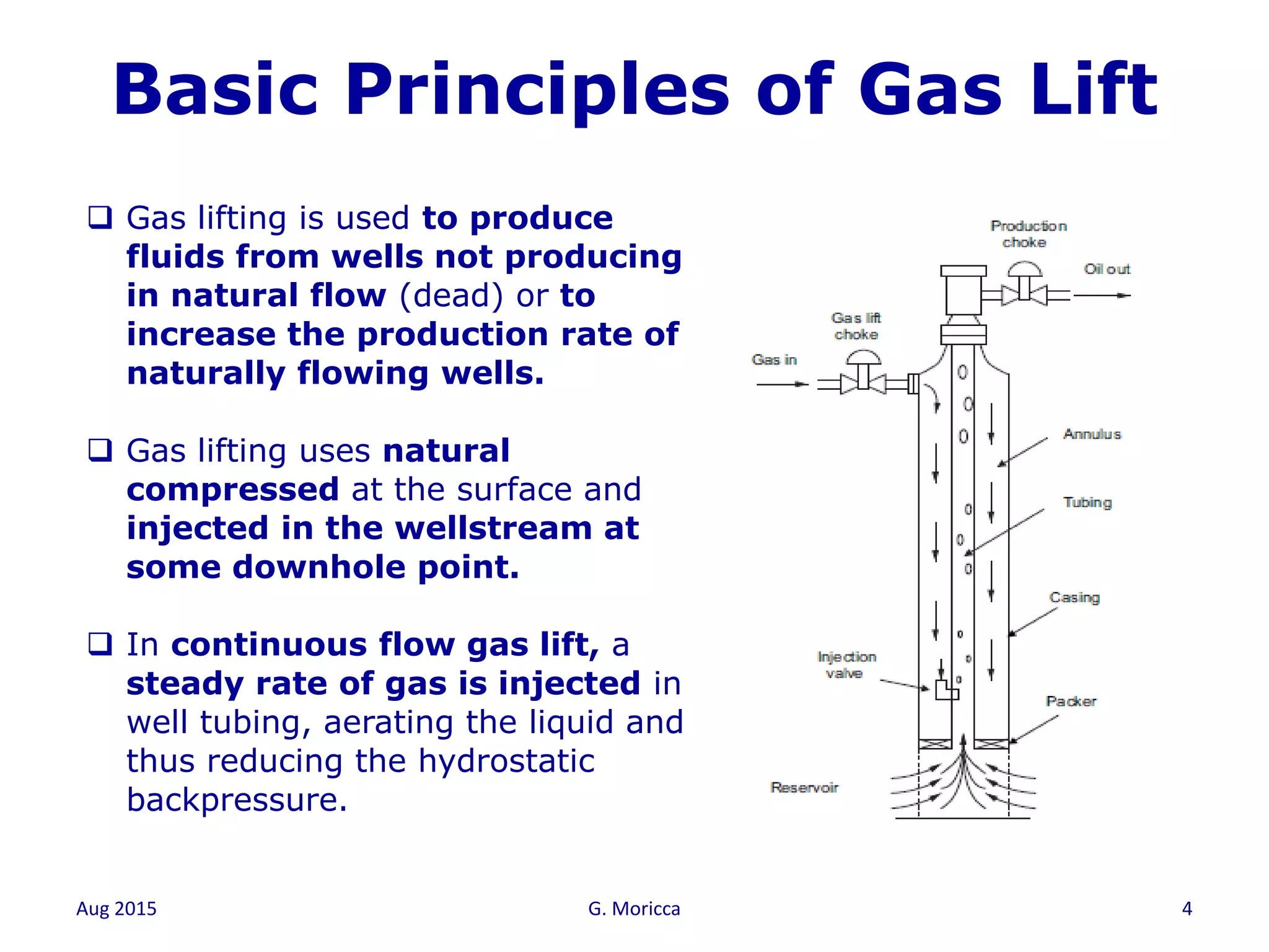
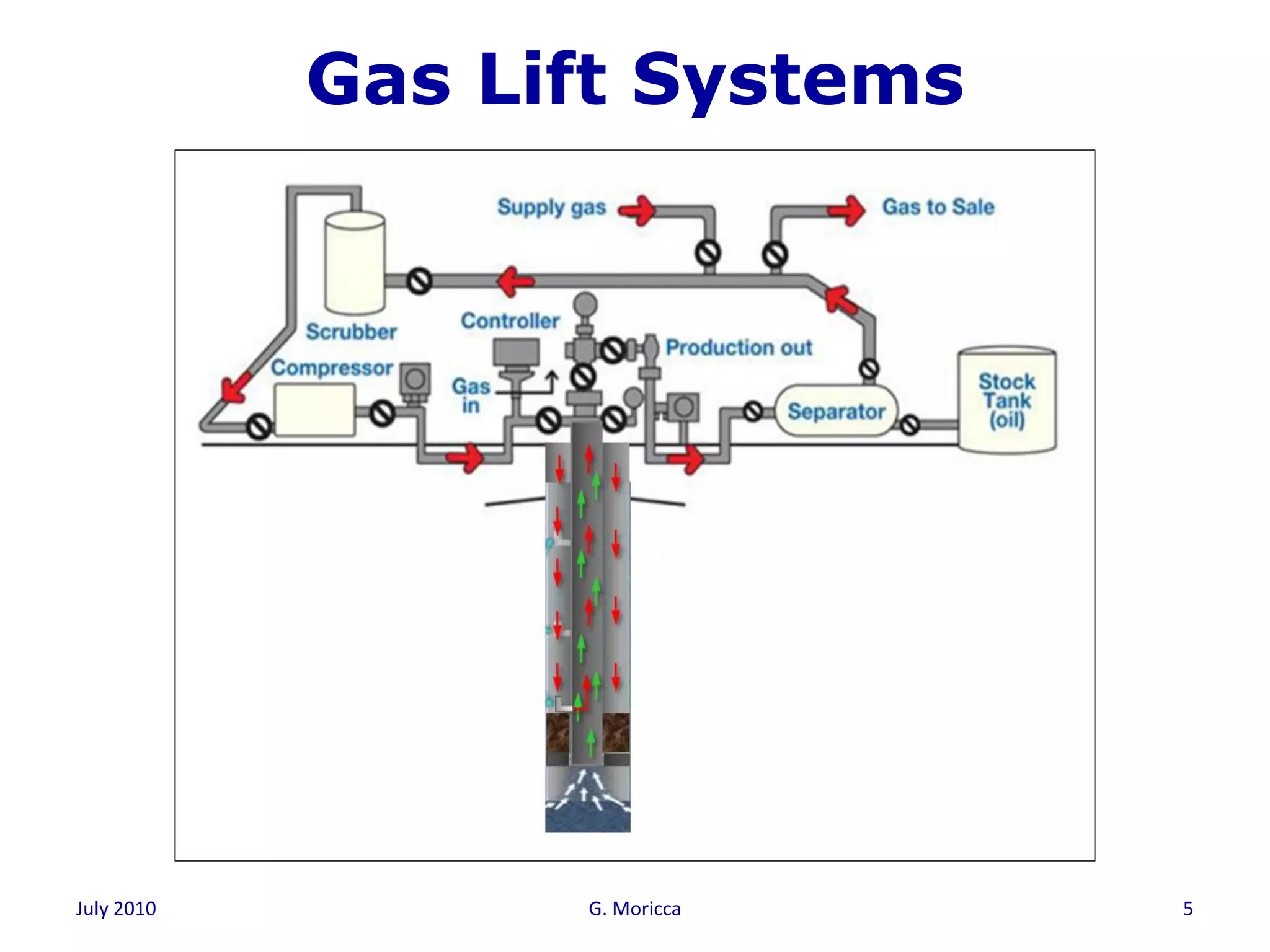
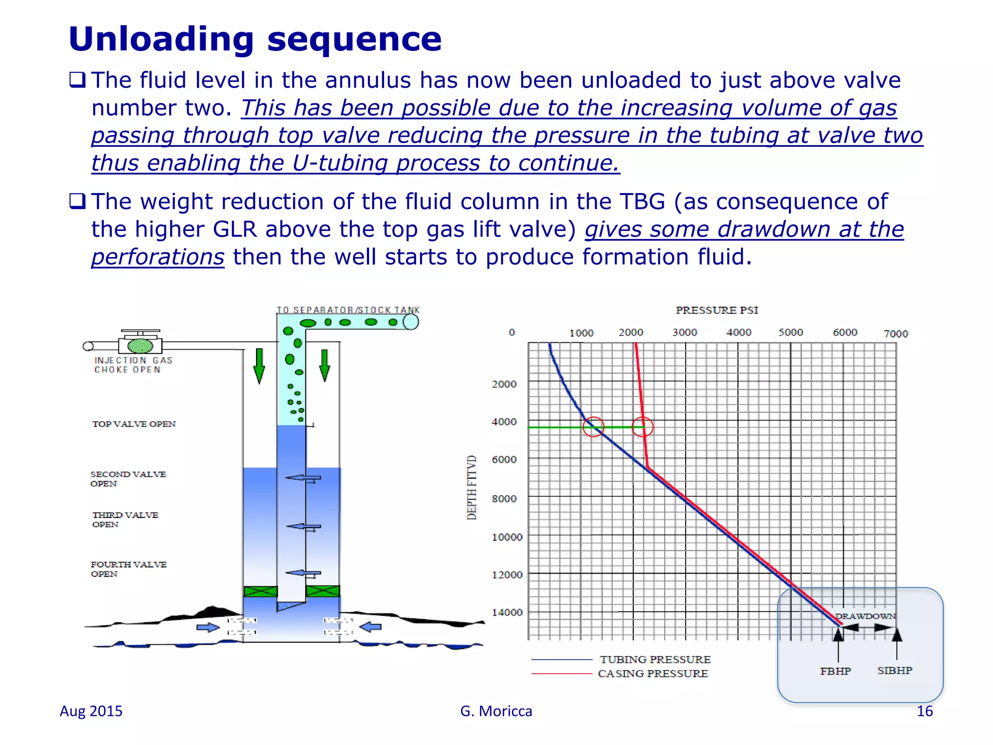
Aug 2015 G. Moricca 1
Gas Lift
One day course
July 2010 G. Moricca 2
One day Gas Lift Course
At the end of this section, you will
know……
1. Why we need Gas Lift
2. Why we need the of Gas Lift Valves
3. How to unload a well
4. How to optimize a Gas Lift well
Aug 2015 G. Moricca 3
Why we need the of Gas Lift
OPERATING
POINT
QACTUALPACTUAL
FLOWING WELLDEAD WELL
Flow rate Q
PressureP
Outflow
(TPR)
Inflow
(IPR)
Aug 2015 G. Moricca 4
 Gas lifting is used to produce
fluids from wells not producing
in natural flow (dead) or to
increase the production rate of
naturally flowing wells.
 Gas lifting uses natural
compressed at the surface and
injected in the wellstream at
some downhole point.
 In continuous flow gas lift, a
steady rate of gas is injected in
well tubing, aerating the liquid and
thus reducing the hydrostatic
backpressure.
Basic Principles of Gas Lift
Gas Lift Systems
July 2010 G. Moricca 5
Aug 2015 G. Moricca 6
Aug 2015 G. Moricca 7
Why we need the of GL Valves
 Gas lifting is a process of lifting fluids from an
oil well by injecting gas into formation
fluids at predetermined depth.
 To achieve an efficient operation and to ensure
that the proper amount of gas is injected at
all times, gas entry must be controlled by
utilizing some kind of downhole control device:
Gas Lift Valves.
Aug 2015 G. Moricca 8
Overview of Gas Lift Valves
 Continuous Gas Lift usually consists of a
number of unloading valves and an
orifice valve at the operating point.
 The role of the unloading gas lift valve
should be to allow smooth, positive
and reliable unloading of the well
 The role of the orifice valve (Operating
valve) should be to allow production
over many years with continuously
changing conditions.
 Several different types of gas lift valves
used in order to achieve this and each
uses a particular design technique
Operating valve
Unloading valve
Unloading valve
Unloading valve
Unloading valve
Aug 2015 G. Moricca 9
 A gas lift valve is designed to stay
closed until certain conditions of
pressure in the annulus and
tubing are met.
 When the valve opens, it permits gas
or fluid to pass from the casing
annulus into the tubing
 An operating gas lift valve is
installed to control the point of gas
injection.
 Valves are installed above the
desired point of injection to unload
the well.
 After unloading, they close to
eliminate gas injection above the
operating valve.
Operating valve
Unloading valve
Unloading valve
Unloading valve
Unloading valve
Overview of Gas Lift Valves
Aug 2015 G. Moricca 10
How the GL Valves work
Aug 2015 G. Moricca 11
Unloading
Sequence
Aug 2015 G. Moricca 12
Unloading sequence
1. After a well is completed or worked over, the fluid level in the
casing and tubing is usually at or near the surface.
2. Casing and Tubing are in hydraulic communication because
the gas lift valve are in open position
3. The gas lift pressure available to unload the well is generally not
sufficient to unload fluid to the desired depth for gas injection.
This is because the pressure caused by the static column of fluid
in the well at the desired depth of injection is greater than the
available gas pressure at the depth of injection.
4. In this case a series of unloading gas lift valves are installed in
the well for the purpose.
5. These valves are designed to use the available gas injection
pressure (depending on gas compression system characteristics)
to unload the well until the desired depth of injection is achieved.
Aug 2015 G. Moricca 13
Unloading sequence
 In this specific case, the fluid level in the casing and the tubing is at surface.
 No gas is being injected into the casing and no fluid is being produced.
 All the gas lift valves are open. The pressure to open the valves is provided by the
weight of the fluid in the casing and tubing.
 The fluid level in the tubing and casing will be determined by the shut in bottom hole
pressure (SIBHP) and the hydrostatic head or weight of the column of fluid which is in
turn determined by the density.
Schlumberger courtesy
Aug 2015 G. Moricca 14
Unloading sequence
 Gas injection into the casing has begun. Fluid is U-tubed through all the open gas lift
valves.
 No formation fluids are being produced because the pressure in the wellbore at
perforation depth is greater than the reservoir pressure i.e. no drawdown.
 All fluid produced is from the casing and the tubing.
 All fluid unloaded from the casing passes through the open gas lift valves. Because
of this, it is important that the well be unloaded at a reasonable rate to prevent damage
to the gas lift valves.
Aug 2015 G. Moricca 15
Unloading sequence
 The fluid level has been unloaded to the top gas lift valve.
 This aerates the fluid above the top gas lift valve, decreasing the fluid density. This
reduces the pressure in the tubing at the top gas lift valve, and also reduces pressure in
the tubing at all valves below the top valve. This is reflected on TBG pressure curve.
 This pressure reduction allows casing fluid below the top gas lift valve to be U-tubed
further down the well and unloaded through valves 2, 3 and 4.
 If this reduction in pressure is sufficient to give some drawdown at the perforations then
the well will start to produce formation fluid.
Aug 2015 G. Moricca 16
Unloading sequence
 The fluid level in the annulus has now been unloaded to just above valve
number two. This has been possible due to the increasing volume of gas
passing through top valve reducing the pressure in the tubing at valve two
thus enabling the U-tubing process to continue.
 The weight reduction of the fluid column in the TBG (as consequence of
the higher GLR above the top gas lift valve) gives some drawdown at the
perforations then the well starts to produce formation fluid.
Aug 2015 G. Moricca 17
Unloading sequence
 The fluid level in the casing has been lowered to a point below the second gas lift
valve. The top two gas lift valves are open and gas being injected through
both valves. All valves below also remain open and continue to pass casing fluid.
 The tubing has now been unloaded sufficiently to sensibly reduce the flowing
bottom hole pressure (FBHP). This increases the differential pressure from the
reservoir to the wellbore and in turn increases the formation fluid flow rate.
Aug 2015 G. Moricca 18
Unloading sequence
 The top gas lift valve is now closed, and all the gas is being injected
through the second valve. When casing pressure operated valves are used
a slight reduction in the casing pressure causes the top valve to close.
With fluid operated and proportional response valves, a reduction in the
tubing pressure at valve depth causes the top valve to close.
 Unloading the well continues with valves 2, 3 and 4 open and casing fluid
being removed through valves 3 and 4.
Aug 2015 G. Moricca 19
Unloading sequence
 The No 3 valve has now been uncovered. Valves 2 and 3 are both open
and passing gas. The bottom valve below the fluid level is also open.
 Note that the deeper the point of injection the lower the FBHP and thus
the greater the drawdown on the well. As well productivity is directly
related to the drawdown then the deeper the injection the greater the
production rate.
Aug 2015 G. Moricca 20
Unloading sequence
 The No. 2 valve is now closed. All gas is being injected through valve No 3. Valve
No 2 is closed by a reduction in casing pressure for casing operated valves or a
reduction in tubing pressure for fluid operated and proportional response valves.
 Valve No 3 is the operating valve in this example. This is because the ability of
the reservoir to produce fluid matches the ability of the tubing to remove fluids
(Inflow/Outflow Performance). The operating valve can either be an orifice valve or
can be a gas lift valve. The valve in mandrel No 4 will remain submerged
unless operating conditions or reservoir conditions change.
Aug 2015 G. Moricca 21
Unloading sequence
Aug 2015 G. Moricca 22
Gas Lift
Optimization
Aug 2015 G. Moricca 23
Gas Lift Optimization Concept
Find the:
1. Optimum injection point for stable flow
conditions (at system design stage)
2. Optimum quantity of gas to be injected to
maximise the oil rate at specific well flow
condition (during the production phase)
Aug 2015 G. Moricca 24
Well Performance Curve
Lift Gas Injection rate vs Oil Rate
0
200
400
600
800
1000
1200
1400
1600
1800
0 0.5 1 1.5 2 2.5 3
Lift Gas Injection Rate mmscf/d
OilRatestb/d
Aug 2015 G. Moricca 25
Gas Lift Optimization
Aug 2015 G. Moricca 26
Question?

One day gas lift system course

  • 1.
    Aug 2015 G.Moricca 1 Gas Lift One day course
  • 2.
    July 2010 G.Moricca 2 One day Gas Lift Course At the end of this section, you will know…… 1. Why we need Gas Lift 2. Why we need the of Gas Lift Valves 3. How to unload a well 4. How to optimize a Gas Lift well
  • 3.
    Aug 2015 G.Moricca 3 Why we need the of Gas Lift OPERATING POINT QACTUALPACTUAL FLOWING WELLDEAD WELL Flow rate Q PressureP Outflow (TPR) Inflow (IPR)
  • 4.
    Aug 2015 G.Moricca 4  Gas lifting is used to produce fluids from wells not producing in natural flow (dead) or to increase the production rate of naturally flowing wells.  Gas lifting uses natural compressed at the surface and injected in the wellstream at some downhole point.  In continuous flow gas lift, a steady rate of gas is injected in well tubing, aerating the liquid and thus reducing the hydrostatic backpressure. Basic Principles of Gas Lift
  • 5.
    Gas Lift Systems July2010 G. Moricca 5
  • 6.
    Aug 2015 G.Moricca 6
  • 7.
    Aug 2015 G.Moricca 7 Why we need the of GL Valves  Gas lifting is a process of lifting fluids from an oil well by injecting gas into formation fluids at predetermined depth.  To achieve an efficient operation and to ensure that the proper amount of gas is injected at all times, gas entry must be controlled by utilizing some kind of downhole control device: Gas Lift Valves.
  • 8.
    Aug 2015 G.Moricca 8 Overview of Gas Lift Valves  Continuous Gas Lift usually consists of a number of unloading valves and an orifice valve at the operating point.  The role of the unloading gas lift valve should be to allow smooth, positive and reliable unloading of the well  The role of the orifice valve (Operating valve) should be to allow production over many years with continuously changing conditions.  Several different types of gas lift valves used in order to achieve this and each uses a particular design technique Operating valve Unloading valve Unloading valve Unloading valve Unloading valve
  • 9.
    Aug 2015 G.Moricca 9  A gas lift valve is designed to stay closed until certain conditions of pressure in the annulus and tubing are met.  When the valve opens, it permits gas or fluid to pass from the casing annulus into the tubing  An operating gas lift valve is installed to control the point of gas injection.  Valves are installed above the desired point of injection to unload the well.  After unloading, they close to eliminate gas injection above the operating valve. Operating valve Unloading valve Unloading valve Unloading valve Unloading valve Overview of Gas Lift Valves
  • 10.
    Aug 2015 G.Moricca 10 How the GL Valves work
  • 11.
    Aug 2015 G.Moricca 11 Unloading Sequence
  • 12.
    Aug 2015 G.Moricca 12 Unloading sequence 1. After a well is completed or worked over, the fluid level in the casing and tubing is usually at or near the surface. 2. Casing and Tubing are in hydraulic communication because the gas lift valve are in open position 3. The gas lift pressure available to unload the well is generally not sufficient to unload fluid to the desired depth for gas injection. This is because the pressure caused by the static column of fluid in the well at the desired depth of injection is greater than the available gas pressure at the depth of injection. 4. In this case a series of unloading gas lift valves are installed in the well for the purpose. 5. These valves are designed to use the available gas injection pressure (depending on gas compression system characteristics) to unload the well until the desired depth of injection is achieved.
  • 13.
    Aug 2015 G.Moricca 13 Unloading sequence  In this specific case, the fluid level in the casing and the tubing is at surface.  No gas is being injected into the casing and no fluid is being produced.  All the gas lift valves are open. The pressure to open the valves is provided by the weight of the fluid in the casing and tubing.  The fluid level in the tubing and casing will be determined by the shut in bottom hole pressure (SIBHP) and the hydrostatic head or weight of the column of fluid which is in turn determined by the density. Schlumberger courtesy
  • 14.
    Aug 2015 G.Moricca 14 Unloading sequence  Gas injection into the casing has begun. Fluid is U-tubed through all the open gas lift valves.  No formation fluids are being produced because the pressure in the wellbore at perforation depth is greater than the reservoir pressure i.e. no drawdown.  All fluid produced is from the casing and the tubing.  All fluid unloaded from the casing passes through the open gas lift valves. Because of this, it is important that the well be unloaded at a reasonable rate to prevent damage to the gas lift valves.
  • 15.
    Aug 2015 G.Moricca 15 Unloading sequence  The fluid level has been unloaded to the top gas lift valve.  This aerates the fluid above the top gas lift valve, decreasing the fluid density. This reduces the pressure in the tubing at the top gas lift valve, and also reduces pressure in the tubing at all valves below the top valve. This is reflected on TBG pressure curve.  This pressure reduction allows casing fluid below the top gas lift valve to be U-tubed further down the well and unloaded through valves 2, 3 and 4.  If this reduction in pressure is sufficient to give some drawdown at the perforations then the well will start to produce formation fluid.
  • 16.
    Aug 2015 G.Moricca 16 Unloading sequence  The fluid level in the annulus has now been unloaded to just above valve number two. This has been possible due to the increasing volume of gas passing through top valve reducing the pressure in the tubing at valve two thus enabling the U-tubing process to continue.  The weight reduction of the fluid column in the TBG (as consequence of the higher GLR above the top gas lift valve) gives some drawdown at the perforations then the well starts to produce formation fluid.
  • 17.
    Aug 2015 G.Moricca 17 Unloading sequence  The fluid level in the casing has been lowered to a point below the second gas lift valve. The top two gas lift valves are open and gas being injected through both valves. All valves below also remain open and continue to pass casing fluid.  The tubing has now been unloaded sufficiently to sensibly reduce the flowing bottom hole pressure (FBHP). This increases the differential pressure from the reservoir to the wellbore and in turn increases the formation fluid flow rate.
  • 18.
    Aug 2015 G.Moricca 18 Unloading sequence  The top gas lift valve is now closed, and all the gas is being injected through the second valve. When casing pressure operated valves are used a slight reduction in the casing pressure causes the top valve to close. With fluid operated and proportional response valves, a reduction in the tubing pressure at valve depth causes the top valve to close.  Unloading the well continues with valves 2, 3 and 4 open and casing fluid being removed through valves 3 and 4.
  • 19.
    Aug 2015 G.Moricca 19 Unloading sequence  The No 3 valve has now been uncovered. Valves 2 and 3 are both open and passing gas. The bottom valve below the fluid level is also open.  Note that the deeper the point of injection the lower the FBHP and thus the greater the drawdown on the well. As well productivity is directly related to the drawdown then the deeper the injection the greater the production rate.
  • 20.
    Aug 2015 G.Moricca 20 Unloading sequence  The No. 2 valve is now closed. All gas is being injected through valve No 3. Valve No 2 is closed by a reduction in casing pressure for casing operated valves or a reduction in tubing pressure for fluid operated and proportional response valves.  Valve No 3 is the operating valve in this example. This is because the ability of the reservoir to produce fluid matches the ability of the tubing to remove fluids (Inflow/Outflow Performance). The operating valve can either be an orifice valve or can be a gas lift valve. The valve in mandrel No 4 will remain submerged unless operating conditions or reservoir conditions change.
  • 21.
    Aug 2015 G.Moricca 21 Unloading sequence
  • 22.
    Aug 2015 G.Moricca 22 Gas Lift Optimization
  • 23.
    Aug 2015 G.Moricca 23 Gas Lift Optimization Concept Find the: 1. Optimum injection point for stable flow conditions (at system design stage) 2. Optimum quantity of gas to be injected to maximise the oil rate at specific well flow condition (during the production phase)
  • 24.
    Aug 2015 G.Moricca 24 Well Performance Curve Lift Gas Injection rate vs Oil Rate 0 200 400 600 800 1000 1200 1400 1600 1800 0 0.5 1 1.5 2 2.5 3 Lift Gas Injection Rate mmscf/d OilRatestb/d
  • 25.
    Aug 2015 G.Moricca 25 Gas Lift Optimization
  • 26.
    Aug 2015 G.Moricca 26 Question?