More Related Content Similar to Inertia dynamic type fb_specsheet Similar to Inertia dynamic type fb_specsheet (15) More from Electromate (20) 1. 18
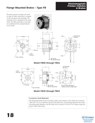
Flange Mounted Brakes – Type FB
Electromagnetic
Friction Clutches
& Brakes
FB series power-on brakes are used
to stop or hold a load that is coupled
to the armature hub assembly. The
armature hub is attached to the load
shaft. The field assembly is mounted
to a bulkhead that is perpendicular
to the shaft.
Model FB08 through FB26
Model FB30 through FB42
H Square
I Pilot Dia.
J Pitch
Circle Dia.
K Dia. (4) Places
A
NF
B
G Dia. M Dia.
.020 Air Gap
.005 Set by Customer
C Dia.
D Dia.
(2) Set Screws
90° Apart
X
Y
L
H
Square
J Pitch
Circle Dia.
I Pilot Dia.
K Dia. (4) Places
A
F
N
B
M Dia.
.005 Air Gap
.020 Set by Customer
G Dia.
(2) Set Screws
90° Apart
Screw Terminals With Nylon
Insulators, Screws & Rubber Boots
X
C Dia.
Y
D Dia.
15°
15°
Customer Shall Maintain:
the perpendicularity of the mounting surface with respect to the shaft not to exceed
.005 inch T.I.R. at a diameter equal to the bolt circle; concentricity between the brake
mounting pilot diameter and the shaft not to exceed .010 inch T.I.R; initial air gap set-
ting of .005-.020 inches.
ELECTROMATE
Toll Free Phone (877) SERVO98
Toll Free Fax (877) SERV099
www.electromate.com
sales@electromate.com
Sold & Serviced By:
2. 19
Flange Mounted Brakes – Type FB
Electromagnetic
Friction Clutches
& Brakes
INERTIA
LB. – IN.2
STATIC
MODEL TORQUE ARM & WGT.
NO. LB. – IN. HUB OZ.
FB08 2.5 .0011 2.0
FB11 6 .0024 3.2
FB15 10 .026 3.8
FB17 15 .031 11
FB19 25 .042 12
FB22 50 .070 20
FB26 80 .320 28
FB30 125 .561 35
FB42 250 2.30 60
MODEL
90 VDC 24 VDC 12 VDC
NO. AMPS OHMS AMPS OHMS AMPS OHMS
FB08 .049 1970 .117 205 .246 48.8
FB11 .047 1930 .198 121 .447 26.8
FB15 .042 2150 .183 132 .380 31.6
FB17 .066 1369 .289 83 .561 21.4
FB19 .074 1213 .322 74.4 .574 20.9
FB22 .079 1140 .322 74.6 .628 19.1
FB26 .092 980 .374 64.2 .760 15.8
FB30 .091 988 .378 65.3 .729 16.5
FB42 .124 722 .468 51.2 .934 12.84
Mechanical Electrical
Lead wire is UL recognized style 1213, 1015 or 1430, 22 gage.
Insulation is .050Љ O.D. on 08, 11, 15 units; .064Љ or .095Љ O.D. on all other units.
NOTES:
1. 08 units have set screws 120° apart.
HUB KEYWAY
MODEL A B C D F G H I J K L NOMINAL KEYWAY M N
NO. MAX. NOM. MAX. NOM. MAX. ± .001 MAX. ± .001 NOM. MIN. ± .500 BORE X Y MAX. NOM.
1
/8
FB08 .885 .634 .905 3
/16 .034 N.A. .980 1.1995 1.030 .094 12.00 N.A. SET SCREWS .500 .070
1
/4
ONLY
3
/16
FB11 .954 .650 1.160 1
/4 .052 N.A. 1.230 1.498 1.312 .123 12.00 N.A. SET SCREWS .687 .093
5
/16
ONLY
1
/4
FB15 1.304 .867 1.500 5
/16 .063 N.A. 1.567 1.999 1.750 .156 12.00 N.A. SET SCREWS .960 .125
3
/8
ONLY
1
/4
1
/4 .0625 – .0655 .285 – .290
FB17 1.269 .848 1.780 5
/16 .064 .751 1.943 2.436 2.125 .186 12.00 5
/16 .0625 – .0655 .347 – .352 1.190 .115
3
/8
3
/8 .094 – .097 .417 – .427
5
/16
5
/16 .0625 – .0655 .347 – .352
FB19 1.330 .901 2.000 3
/8 .062 .751 1.943 2.436 2.125 .186 12.00 3
/8 .094 – .097 .417 – .427 1.190 .115
1
/2
1
/2 .125 – .128 .560 – .567
FB22 1.757 1.173 2.260
3
/8
.096 1.001 2.322 2.873 2.500 .160 18.00
3
/8 .094 – .097 .417 – .427
1.005 .1151
/2
1
/2 .125 – .128 .560 – .567
3
/8
3
/8 .094 – .097 .417 – .427
FB26 1.815 1.300 2.645 1
/2 .080 1.062 2.630 3.499 3.125 .182 18.00 1
/2 .125 – .128 .560 – .567 1.440 .150
5
/8
5
/8 .1885 – .1905 .709 – .716
1
/2 SCREW 1
/2 .125 – .128 .560 – .567
FB30 1.900 1.310 3.268 5
/8 .097 1.751 3.200 4.186 3.750 .182 TER- 5
/8 .1885 – .1905 .709 – .716 1.825 .150
3
/4 MINALS 3
/4 .1885 – .1905 .836 – .844
1
/2
1
/2 .125 – .128 .560 – .567
FB42 2.280 1.490 4.270
5
/8
.097 1.875 4.255 5.624 5.000 .276
SCREW 5
/8 .1885 – .1905 .709 – .716
3
/4 TER- 3
/4 .1885 – .1905 .836 – .844 2.195 .250
7
/8 MINALS 7
/8 .1885 – .1905 .962 – .970
1 1 .251 – .253 1.113 – 1.121
Dimensions
See page 3 for ordering information
PRIME MOVERLOAD
ELECTROMATE
Toll Free Phone (877) SERVO98
Toll Free Fax (877) SERV099
www.electromate.com
sales@electromate.com
Sold & Serviced By:
3. 3
Ordering Information
Electromagnetic
Friction Clutches & Brakes
Spring Applied Brakes
PART NUMBERING SYSTEM FOR PRODUCTS ON PAGES 3 TO 35 OF THIS CATALOG
A A B B - C D E F
DIGIT DIGIT MODEL NO.
1 7 FSB
1 9 FSBR
2 1 FSBR
(MANUAL
RELEASE)
0 1 SL
0 3 BSL
0 5 FL
0 7 SO
0 9 FO
1 1 FB
1 3 SLB
1 5 SOB
1 8 SAB
DIGIT DIGIT SIZE
0 1 001
0 2 003
0 3 007
0 4 015
0 5 035
0 6 050
0 7 100
0 8 200
0 9 08
1 0 11
1 1 15
1 2 17
1 3 19
1 4 22
1 5 26
1 6 30
1 7 42
1 8 20
1 9 90
2 1 180
2 3 400
2 5 1200
DIGIT VOLTS
1 90 VDC
2 24 VDC
3 12 VDC
4 120 VAC
DIGIT BORE
1 1
/8
2 3
/16
3 1
/4
4 5
/16
5 3
/8
6 1
/2
7 5
/8
8 3
/4
9 7
/8
0 1
11 1 1
/8
12 1 1
/4
13 1 3
/8
14 1 1
/2
DIGIT DRIVE
1 ZERO
BACKLASH
2 HEX/SQUARE
3 DYNAMIC
(MANUAL RELEASE
BRAKE ONLY)
4 STATIC
(MANUAL RELEASE
BRAKE ONLY)
5 SPLINE
DIGIT CONNECTION
1 LEAD
WIRES
2 SCREW
TERMINALS
3 SWITCH
(MANUAL RELEASE
BRAKE ONLY)
4 CONDUIT
BOX
How To Order
A. Select the model number from the product guide.
B. Select the size of the clutch or brake.
C. Select the voltage.
D.Select the bore diameter.
E. For all power-on clutches and brakes, select 1. For model FSBR and SAB-20,
& 90, select 2. For model FSB spring applied brakes, select 1 or 2. For man-
ual release brakes, select 3 or 4. For SAB-180, 400, & 1200, select 5.
F. For all clutches and brakes, refer to the product guide and specify 1 or 2.
For manual release brakes, if a switch is desired, select 3, otherwise use a 1.
Example
SL11 clutch, 24 volts, 1
/4Љ bore
Part No. 0110-2311
FSB050 brake, 90 volts, 3
/8Љ bore, Hex drive
Part No. 1706-1521
ELECTROMATE
Toll Free Phone (877) SERVO98
Toll Free Fax (877) SERV099
www.electromate.com
sales@electromate.com
Sold & Serviced By: