Tata AIG General Insurance Company - Insurer Innovation Award 2024
Inertia dynamics sf1000fhd_specsheet
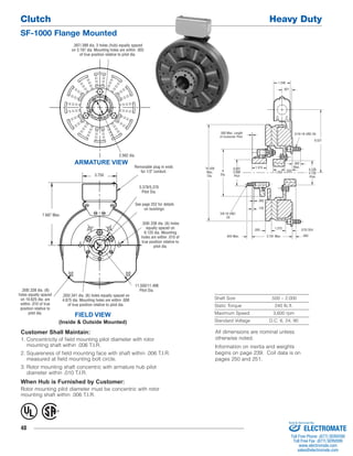
1. Clutch Heavy Duty
SF-1000 Flange Mounted
48
.062
Shaft Size .500 – 2.000
Static Torque 240 lb.ft.
Maximum Speed 3,600 rpm
Standard Voltage D.C. 6, 24, 90
.397/.388 dia. 3 holes (hub) equally spaced
on 3.187 dia. Mounting holes are within .003
of true position relative to pilot dia.
2.562 dia.
ARMATURE VIEW
FIELD VIEW
(Inside & Outside Mounted)
Customer Shall Maintain:
1. Concentricity of field mounting pilot diameter with rotor
mounting shaft within .006 T.I.R.
2. Squareness of field mounting face with shaft within .006 T.I.R.
measured at field mounting bolt circle.
3. Rotor mounting shaft concentric with armature hub pilot
diameter within .010 T.I.R.
When Hub is Furnished by Customer:
Rotor mounting pilot diameter must be concentric with rotor
mounting shaft within .006 T.I.R.
.921
.093 Max. Length 5/16-18 UNC-3A
of Customer Pilot.
.250
.500
.843 Max.
1.375
.570/.554
..093
3/8-16 UNC-
2A
6.531
.562
Max.
1.546
4.128
4.126
Pilot
1.250
1.375
6
Dia.
10.328
Max.
Dia.
.125
3.781 Max.
4.001
3.999
Pilot
Removable plug in ends
for 1/2" conduit.
5.378/5.376
Pilot Dia.
7.687 Max.
3.750
.358/.338 dia. (6) holes
equally spaced on
6.125 dia. Mounting
holes are within .010 of
true position relative to
pilot dia.
11.500/11.498
.358/.338 dia. (8) Pilot Dia.
holes equally spaced
on 10.625 dia. are
within .010 of true
position relative to
pilot dia.
.350/.341 dia. (6) holes equally spaced on
4.875 dia. Mounting holes are within .008
of true position relative to pilot dia.
See page 252 for details
on bushings.
® U
L
All dimensions are nominal unless
otherwise noted.
Information on inertia and weights
begins on page 239. Coil data is on
pages 250 and 251.
Sold & Serviced By:
ELECTROMATE
Toll Free Phone (877) SERVO98
Toll Free Fax (877) SERV099
www.electromate.com
sales@electromate.com
2. Heavy Duty Clutch
SF-1000 Flange Mounted
49
3-1
1
3-4
3-2
3-3
3-6
3-5
2
3
(Shipped
Assembled)
5 6
4
7
8A
9A
10
10
9B
8B
Drawing I-25581
Item Description Part Number Qty.
9B Field, Outside Mounted 1
6 Volt 5202-451-011
24 Volt 5202-451-013
90 Volt 5202-451-014
10 Conduit Box 5200-101-012 1
How to Order:
1. Specify Bore Size for Item 6.
2. Specify Voltage for Item 9A or 9B.
3. Specify Inside Mounted for Items 8A and 9A or Outside
Mounted for Items 8B and 9B.
4. See Controls Section.
Example:
SF-1000 Clutch Coupling, Heavy Duty per I-25581 - 90 Volt,
Inside Mounted, 1-1/4" Bore (Item 6)
These units, when used in conjunction with the correct
Warner Electric conduit box, meet the standards of UL508
and are listed under guide card #NMTR, file #59164.
These units are CSA certified under file #LR11543
Item Description Part Number Qty.
1 Splined Hub 540-0147 1
2 Mounting Accessory 5202-101-001 1
3 Armature & Splined Adapter 5202-111-001 1
3-1 Armature 5322-111-036 1
3-2 Splined Adapter 104-0009 1
3-3 Autogap Accessory 5322-101-004 1
3-4 Screw 797-0341 3
3-5 Locknut 661-0004 3
3-6 Spacer 748-0333 3
4 Mounting Accessory 5201-101-007 1
5 Rotor 1
Standard Friction Material 5202-751-003
†Optional LK Facing 5202-751-007
6 Bushing, Taperlock* 180-0155 to 180-0179 1
7 Rotor Hub 540-0315 1
8A Mounting Accessory, I.M. 5321-101-001 1
8B Mounting Accessory, O.M. 5321-101-002 2
9A Field, Inside Mounted 1
6 Volt 5202-451-004
24 Volt 5202-451-006
90 Volt 5202-451-007
*See page 252 for specific part numbers.
Refer to Service Manual P-215.
†Optional LK facing available. For more information, see
page 232.
Sold & Serviced By:
ELECTROMATE
Toll Free Phone (877) SERVO98
Toll Free Fax (877) SERV099
www.electromate.com
sales@electromate.com