Inertia dynamic type fsbr_specsheet
•
1 like•271 views

This document provides specifications for Inertia Dynamics type FSBR spring applied brakes. It describes the FSBR brakes as being designed for applications requiring minimal space or for motors with short shaft extensions. When mounted, the armature hub is installed on the shaft first, then the brake is installed over the hub and attached to the motor. It includes tables providing model numbers, torque ratings, dimensions, weights and electrical specifications for various FSBR brake models.

Recommended
Recommended
More Related Content
What's hot
What's hot (13)
Viewers also liked
Viewers also liked (18)
Similar to Inertia dynamic type fsbr_specsheet
Similar to Inertia dynamic type fsbr_specsheet (20)
More from Electromate
More from Electromate (20)
Recently uploaded
Recently uploaded (20)
Inertia dynamic type fsbr_specsheet
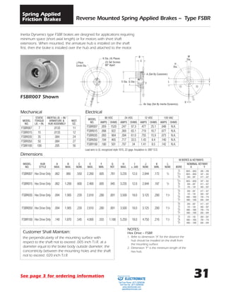
- 1. 31 Reverse Mounted Spring Applied Brakes – Type FSBR Spring Applied Friction Brakes Inertia Dynamics type FSBR brakes are designed for applications requiring minimum space (short axial length) or for motors with short shaft extensions. When mounted, the armature hub is installed on the shaft first, then the brake is installed over the hub and attached to the motor. Customer Shall Maintain: the perpendicularity of the mounting surface with respect to the shaft not to exceed .005 inch T.I.R. at a diameter equal to the brake body outside diameter; the concentricity between the mounting holes and the shaft not to exceed .020 inch T.I.R. STATIC INERTIA LB. – IN.2 MODEL TORQUE ARMATURE & WGT. NO. LB. – IN. HUB ASSEMBLY OZ. FSBR007 7 .0133 11 FSBR015 15 .0133 12 FSBR035 35 .084 24 FSBR050 50 .084 27 FSBR100 100 .205 56 MODEL 90 VDC 24 VDC 12 VDC 120 VAC NO. AMPS OHMS AMPS OHMS AMPS OHMS AMPS OHMS FSBR007 .059 1520 .247 97.3 .477 25.1 .048 N.A. FSBR015 .098 922 .369 65.1 .719 16.7 .077 N.A. FSBR035 .093 964 .394 61.0 .755 15.9 .073 N.A. FSBR050 .194 465 .717 33.5 1.43 8.4 .140 N.A. FSBR100 .180 501 .707 34 1.41 8.5 .142 N.A. Mechanical Electrical Lead wire is UL recognized style 1015, 22 gage. Insulation is .095Љ O.D. NOTES: Hex Drive – FSBR 1. Refer to dimension “A” for the distance the hub should be installed on the shaft from the mounting surface. 2. Dimension “F” is the minimum length of the hex hub. FSBR007 Shown J Pitch Circle Dia. K Dia. (4) Places (2) Set Screws 90° Apart B I C A (Set By Customer) E Dia. G Dia. L Y F H Dia. M Dia. Air Gap (Set By Inertia Dynamics) X M BORES & KEYWAYS MODEL HUB A B C E F G H I J K L NOMINAL KEYWAY NO. STYLE MAX. MAX. NOM. MAX. MIN. REF. MAX. ± .500 NOM. MIN. NOM. BORE X Y 1 /4 .0625 – .0655 .285 – .290 FSBR007 Hex Drive Only .062 .960 .550 2.260 .605 .781 3.235 12.0 2.844 .172 5 /8 5 /16 .0625 – .0655 .347 – .352 3 /8 .094 – .097 .417 – .427 5 /16 .0625 – .0655 .347 – .352 FSBR015 Hex Drive Only .062 1.200 .600 2.400 .605 .945 3.235 12.0 2.844 .187 5 /8 3 /8 .094 – .097 .417 – .427 1 /2 .125 – .128 .560 – .567 3 /8 .094 – .097 .417 – .427 FSBR035 Hex Drive Only .094 1.905 .239 2.810 .280 .891 3.500 18.0 3.125 .200 11 /8 1 /2 .125 – .128 .560 – .567 5 /8 .1885 – .1905 .709 – .716 3 /4 .1885 – .1905 .836 – .844 3 /8 .094 – .097 .417 – .427 FSBR050 Hex Drive Only .094 1.905 .239 2.810 .280 .891 3.500 18.0 3.125 .200 11 /8 1 /2 .125 – .128 .560 – .567 5 /8 .1885 – .1905 .709 – .716 3 /4 .1885 – .1905 .836 – .844 1 /2 .125 – .128 .560 – .567 FSBR100 Hex Drive Only .140 1.870 .545 4.000 .555 1.188 5.250 18.0 4.750 .216 11 /2 5 /8 .1885 – .1905 .709 – .716 3 /4 .1885 – .1905 .836 – .844 Dimensions See page 3 for ordering information ELECTROMATE Toll Free Phone (877) SERVO98 Toll Free Fax (877) SERV099 www.electromate.com sales@electromate.com Sold & Serviced By:
- 2. 32 Manual Release, Spring Applied Brake – Type FSBR Spring Applied Friction Brakes ∅.25 Ref. (2) #8-32 Set Screws ∅.180 (4) Holes Eq. Sp. on .170 a ∅2.844 Bolt Circle Mount with a #8 Socket Head Cap Screw Only Inertia Dynamics features a type FSBR015 spring applied brake with a manual release lever. The brake incor- porates a lever which is rotated to mechanically engage the clapper plate. The clapper plate acts against the compression springs and allows the armature disc to spin freely. The brake is then free of torque. An optional microswitch is activated on the field assembly to disconnect power to your system in case of an accidental start-up with the brake manually released. To return the brake to normal operation, the lever is rotat- ed to re-engage the brake and pro- duce torque. Typical applications include wheel- chairs, three-wheel carts/scooters, and fractional horsepower motors. The brake is available with a higher static torque rating for non-dynamic braking applications where only a statically engaged parking brake is needed. For variations on the manual release brake configuration, in support of high volume OEM applications, consult Inertia Dynamics. Caution: Inertia Dynamics recommends the use of a switch or other method to ensure this brake is not operat- ed while it is in the manually released mode. Customer Shall Maintain: the concentricity between mounting holes and mounting shaft not to exceed .020 T.I.R.; the perpendicularity of mounting face with respect to shaft not to exceed .005 T.I.R. ELECTROMATE Toll Free Phone (877) SERVO98 Toll Free Fax (877) SERV099 www.electromate.com sales@electromate.com Sold & Serviced By:
- 3. 33 Manual Release, Spring Applied Brake – Type FSBR Spring Applied Friction Brakes Bore Dimensions Electrical HUB BORE NOM. HEX KEYWAY .3130 – .3145 5 /16 5 /8 1 /32 x 1 /16 .3755 – .3770 3 /8 5 /8 3 /64 x 3 /32 .5005 – .5020 1 /2 3 /4 1 /16 x 1 /8 VOLTS WATTS AMPS. OHMS. 90 VDC 8.8 .098 922 24 VDC 8.9 .369 65.1 12 VDC 8.6 .719 16.7 120 VAC 8.7 .077 N.A. NOTES: 1. Coil lead data: 22 AWG, 7/30 stranded, 105°C, 600V, UL, style 1430, insulation is .064؆ O.D. Mechanical DYNAMIC STATIC* INERTIA (LB.-IN.2 ) WGT. STYLE STYLE ARM & HUB OZ. Static Torque (LB. – IN.) 15 30 .0133 34 oz. ● 16 lbs. pull force maximum at 3.500 length on lever arm. *For park & hold, static braking conditions only. Switch must be operated within the rated limits for voltage and current. Switch Data Ratings: 5 amps, 125/250 VAC Double-Throw Contacts Short Solder Terminals Engineering may substitute a switch of equal specifications. φ 2.400 Max. 13Њ Ref. 15Њ Nom. 3.50 3.75 .135 Ref. 1.20 Max. 12” Lead Wires φ 3.235 3.220 .062 .042 .645 .602 Snap-Action Switch Assembly Brake Released & Free of Torque See page 3 for ordering information ELECTROMATE Toll Free Phone (877) SERVO98 Toll Free Fax (877) SERV099 www.electromate.com sales@electromate.com Sold & Serviced By:
- 4. 3 Ordering Information Electromagnetic Friction Clutches & Brakes Spring Applied Brakes PART NUMBERING SYSTEM FOR PRODUCTS ON PAGES 3 TO 35 OF THIS CATALOG A A B B - C D E F DIGIT DIGIT MODEL NO. 1 7 FSB 1 9 FSBR 2 1 FSBR (MANUAL RELEASE) 0 1 SL 0 3 BSL 0 5 FL 0 7 SO 0 9 FO 1 1 FB 1 3 SLB 1 5 SOB 1 8 SAB DIGIT DIGIT SIZE 0 1 001 0 2 003 0 3 007 0 4 015 0 5 035 0 6 050 0 7 100 0 8 200 0 9 08 1 0 11 1 1 15 1 2 17 1 3 19 1 4 22 1 5 26 1 6 30 1 7 42 1 8 20 1 9 90 2 1 180 2 3 400 2 5 1200 DIGIT VOLTS 1 90 VDC 2 24 VDC 3 12 VDC 4 120 VAC DIGIT BORE 1 1 /8 2 3 /16 3 1 /4 4 5 /16 5 3 /8 6 1 /2 7 5 /8 8 3 /4 9 7 /8 0 1 11 1 1 /8 12 1 1 /4 13 1 3 /8 14 1 1 /2 DIGIT DRIVE 1 ZERO BACKLASH 2 HEX/SQUARE 3 DYNAMIC (MANUAL RELEASE BRAKE ONLY) 4 STATIC (MANUAL RELEASE BRAKE ONLY) 5 SPLINE DIGIT CONNECTION 1 LEAD WIRES 2 SCREW TERMINALS 3 SWITCH (MANUAL RELEASE BRAKE ONLY) 4 CONDUIT BOX How To Order A. Select the model number from the product guide. B. Select the size of the clutch or brake. C. Select the voltage. D.Select the bore diameter. E. For all power-on clutches and brakes, select 1. For model FSBR and SAB-20, & 90, select 2. For model FSB spring applied brakes, select 1 or 2. For man- ual release brakes, select 3 or 4. For SAB-180, 400, & 1200, select 5. F. For all clutches and brakes, refer to the product guide and specify 1 or 2. For manual release brakes, if a switch is desired, select 3, otherwise use a 1. Example SL11 clutch, 24 volts, 1 /4Љ bore Part No. 0110-2311 FSB050 brake, 90 volts, 3 /8Љ bore, Hex drive Part No. 1706-1521 ELECTROMATE Toll Free Phone (877) SERVO98 Toll Free Fax (877) SERV099 www.electromate.com sales@electromate.com Sold & Serviced By: