Handwritten Text Recognition for manuscripts and early printed texts
Inertia dynamics pcb1225_1000f_specsheet
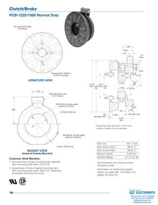
1. Clutch/Brake
PCB-1225/1000 Normal Duty
196
1.640
* Mounting holes are within .010 of true
position relative to pilot diameter.
Shaft Size .500 – 2.500
Static Torque Clutch 465 lb. ft.
Static Torque Brake 240 lb. ft.
Maximum Speed 3,000 rpm
Standard Voltage D.C. 6, 24, 90
ARMATURE VIEW
Removable plug in ends
for 1/2" conduit.
.358/.338 dia. (6) holes equally
spaced on 6.125 dia.*
5.378/5.376 Pilot Dia.
Customer Shall Maintain:
1. Concentricity of brake mounting pilot diameter
with mounting shaft within .010 T.I.R.
2. Squareness of brake magnet mounting face
with mounting shaft within .006 T.I.R. measured
at magnet mounting bolt circle.
4.125 Dia.
.593
.562 1.453
.562
Max.
.171
Max.
6.531
5.750
1.546
.921
.093 When New
2.906
5/16-
18
UNC-
3A
1.750
1.906
13.140
Max. 12.625
Dia.
5.877
Dia. 4.625
Dia.
6.250
Max.
.093 When New
MAGNET VIEW
(Inside & Outside Mounted)
.358/.338 dia. (8) holes equally
spaced on 10.625 dia.*
11.500/11.498 Pilot Dia.
3.750
See page 252 for details
on Bushings.
See page 230 for details on
Drive Pin mountings.
7.687
All dimensions are nominal unless
otherwise noted.
Information on inertia and weights
begins on page 239. Coil data is on
pages 250 and 251.
Sold & Serviced By:
ELECTROMATE
Toll Free Phone (877) SERVO98
Toll Free Fax (877) SERV099
www.electromate.com
sales@electromate.com
2. Clutch/Brake
PCB-1225/1000 Normal Duty
197
Drawing I-25610
How to Order:
1. Specify Voltage for Item 4 and Item 11A or 11B.
2. Specify left hand or right hand hub for Item 5. Bushing
enters from magnet side for L.H. hub and from hub
side for R.H.
3. Specify Bore Size for Item 7.
4. Specify Inside Mounted for Items 10A and 11A or
Outside Mounted for Items 10B and 11B.
5. See Controls Section.
Example:
PCB-1225/1000 Clutch Brake per
I-25610 - 90 Volt, Left Hand hub,
1-1/2" Bore, Inside Mounted
These units meet the standards of UL508 and are listed
under guide card #NMTR2, file #59164. These units are
CSA certified under file #LR11543.
4-1
7
4
3
2
1
6
6-1
5-2
8 10A
11A
11A-1
12
11B
11B-1
12
10B
9
5 (Shipped Assembled)
5-1
Item Description Part Number Qty.
1 Armature 5303-111-009 1
2 Autogap Accessory 5201-101-008 4
3 Mounting Accessory 5321-101-001 1
4 Magnet 1
6 Volt 5333-631-008
90 Volt 5333-631-009
†90 Volt LK Facing 5333-631-013
4-1 Terminal Accessory 5311-101-001 1
5 Magnet Hub 1
Left Hand (shown) 5302-541-004
Right Hand 5302-541-005
5-1 Collector Ring 5301-749-001 1
5-2 Collector Ring Accessory 5303-101-004 1
6 Brushholder 5300-178-001 1
6-1 Brush 176-0001 4
7 Bushing* 1
1/2" to 2-1/2" Bore 180-0185 to 180-0217
8 Armature 5302-111-013 1
9 Autogap Accessory 5201-101-008 3
10A Mounting Accessory - I.M. 5321-101-001 1
10B Mounting Accessory - O.M. 5321-101-002 2
11A Magnet - Inside Mounted 1
6 Volt 5312-631-004
24 Volt 5312-631-005
90 Volt 5312-631-006
Item Description Part Number Qty.
11A-1 Terminal Accessory 5311-101-001 1
11B Magnet - Outside Mounted 1
6 Volt 5312-631-011
24 Volt 5312-631-013
90 Volt 5312-631-012
11B-1 Terminal Accessory 5311-101-001 1
12 Conduit Box 5200-101-011 1
*See page 252 for specific part numbers.
Refer to Service Manual P-214.
†Optional LK facing available. For more information,
see page 232.
Sold & Serviced By:
ELECTROMATE
Toll Free Phone (877) SERVO98
Toll Free Fax (877) SERV099
www.electromate.com
sales@electromate.com