1. 22
S E R V O S Y S T E M S
K o l l m o r g e n GOLDL I N E ®
XT & S E R V O STAR®
CD/600 S y s t e m s
SYSTEM
OVERVIEW
www.DanaherMotion.com•815-226-2222
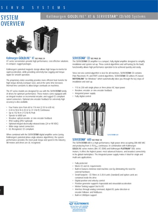
Kollmorgen GOLDLINE®
XT SEE PAGE 24
XT series servomotors provide high performance, cost-effective solutions
in compact, rugged packages.
Kollmorgen’s patented magnetic design allows high torque-to-inertia for
rapid acceleration, while providing extremely low cogging and torque
ripple for smooth operation.
The proprietary stator assembly provides more efficient heat transfer for
high torque density (compact size), and at the same time increases
thermal time constants to allow longer overloads on machines.
The XT series models are designed for use with the SERVOSTAR family
of drives for optimum performance. These motors come equipped with
an integral resolver or incremental encoder, and rugged CE compliant
swivel connectors. Optional sine encoder feedback for extremely high
accuracy is also available.
• Four frame sizes from 60 to 174 mm (2.35 to 6.85 in)
• 0.44 to 50.6 N-m (0.32 to 37.3 lb-ft) Continuous
• Up to 152 N-m (112 lb-ft) Peak
• Speeds to 6000 rpm
• Resolver, optical encoder, or sine encoder feedback
• IP65 sealing (IP67 optional)
• Optional integral electrically-released brake (24 or 90 VDC)
• Wide range swivel connectors
• UL Recognized, CE compliant
When combined with the SERVOSTAR digital amplifier series (using
Kollmorgen’s patented phase angle advance algorithms), the system
performance provides the most peak torque and speed in the industry.
All motors and drives are UL recognized.
SERVOSTAR®
CD SEE PAGE 28
The SERVOSTAR CD amplifier is a compact, fully digital amplifier designed to simplify
installation and system set-up. Three control algorithms and self-tuning (to the load)
functionality allows high performance operation to be achieved quickly and easily.
Since not one control algorithm is best for all machines, SERVOSTAR CD contains
Pole Placement, PI, and PDFF control algorithms. SERVOSTAR CD utilizes PC-based
MOTIONLINK®
for Windows®
which automatically takes you through the key steps of
installation and start up.
• 115 to 230 volt single phase or three phase AC input power
• Resolver, encoder, or sine encoder feedback
• Integrated power supply
• Fully digital control
SERVOSTAR®
600 SEE PAGE 34
The SERVOSTAR 600 is a high performance, high power drive accepting 208-480 VAC
and producing from 3-70 ARMS continuous. In combination with Kollmorgen
GOLDLINE series motors (BH, XT, DDR) and Kollmorgen PLATINUM®
DDL series
motors, it offers the highest power, most advanced features, and broadest connectivity
in the global marketplace. The integrated power supply makes it ideal for single and
multi-axis applications.
• Fully protected
• Meets CE and UL requirements
• Built-in features minimize total machine cost by eliminating the need for
external hardware
• Small footprint - CE Filters in 3-20 A units (standard) and option cards are
contained inside the drive
• Digital position and velocity control
• Position generator supports trapezoidal and sinusoidal acceleration
• Motion Tasking support tied to I/O
• Interface through analog command, digital I/O, pulse direction or
encoder follower, and fieldbuses
• Built-in CANOpen support
SERVOSTAR 600
ELECTROMATE
Toll Free Phone (877) SERVO98
Toll Free Fax (877) SERV099
www.electromate.com
sales@electromate.com
Sold & Serviced By:
3. K o l l m o r g e n GOLDL I N E ®
XT & S E R V O STAR®
CD S y s t e m s
24
S E R V O S Y S T E M S
www.DanaherMotion.com•815-226-2222
XT SERIES MOTORS
4 X 90°
45°
5.59 (.220)KEY SIZE
SEE TABLE
“C” REF
“A” MAX.
“B” REF
2 X 85.9
(3.38)
Ø“E”
Ø“D”
.035 (.0014)
-A-
.076 (.003) A
33.1 (1.30)
16.5 (.65)
115.9
(4.56)
REF
60 (2.36)
4 X Ø79.8 (3.14)
NEMA 23
4 X Ø4.96-5.46 (.195-.215)
THRU, ON Ø66.68 (2.625) B.C.
NEMA 65
4 X Ø5.80-6.29 (.228-.248)
THRU, ON Ø70 (2.756) B.C.
“F”
2.41 ±0.07
(.095 ±.003)
OPTIONAL
MATING PLUGS
NEMA 65
SHAFT DETAIL
MT15xx / MTX15xx
15.88-16.00
(.625-.630)
4.98-5.00
(.196-.197)
“A” MAX. “B” REF. “C” “D” “E” “F” Key Length
Model with brake-without brake with brake-without brake with brake-without brake NEMA 23 NEMA 65 NEMA 23 NEMA 65 NEMA 23 NEMA 65 NEMA 34 NEMA 100
MT(x)1502 158.70 (6.248)-113.4 (4.465) 140.33 (5.525)-95.31 (3.752) 230.38 (9.07)-185.42 (7.30) 20.83 30 no 20 (0.79)
MT(x)1504 174.24 (6.860)-128.94 (5.077) 155.88 (6.137)-110.85 (4.364) 245.87 (9.68)-200.91 (7.91) (0.820) (1.181) keyway 20 (0.79)
MT(x)1506 205.23 (8.080)-160.03 (6.301) 186.97 (7.361)-141.94 (5.588) 277.11 (10.91)-231.90 (9.13) 20 (0.79)
±.76
(±.03)
9.513
9.525
0.3745
0.3750
13.997
14.006
0.5511
0.5515( )( )
38.05
38.15
1.498
1.502
49.99
50.01
1.968
1.969( )( )
MT(x)150x
mm (in)
XT150SERIESMOTORS
PARAMETER SYMBOL UNITS MT1502A1 MT1504A1 MT1506A1 MT1506B1
Horsepower HPRATED hp 0.31 0.50 0.90 0.87
Kilowatts kWRATED kW 0.23 0.37 0.67 0.65
Speed at Rated Power NRATED rpm 6000 6000 6000 6000
Max Operating Speed NMAX rpm 6000 6000 6000 6000
Cont. Torque (Stall) at 40°C Tcs N-m (lb-ft) 0.438 (0.323) 0.742 (0.547) 1.353 (0.998) 1.384 (1.021)
Cont. Torque (Stall) at 25°C Tcs N-m (lb-ft) 0.466 (0.344) 0.790 (0.583) 1.441 (1.063) 1.474 (1.087)
Cont. Line Current Ics ARMS 2.21 2.93 2.89 5.86
Peak Torque Tps N-m (lb-ft) 1.25 (0.92) 2.42 (1.78) 4.62 (3.41) 4.67 (3.44)
Peak Line Current Ips ARMS 7.2 11 11.4 22.7
Max Theoretical Acceleration Z rad/sec2
98013 123864 145746 147062
Torque Sensitivity (Stall) ±10% Kt N-m (lb-ft) ARMS 0.202 (0.149) 0.258 (0.190) 0.476 (0.351) 0.240 (0.177)
Back EMF (Line to Line) ±10% Kb VRMS / krpm 12.2 15.6 28.8 14.5
Max Line-to-Line volts VMAX VRMS 250 250 250 250
DC Res at 25°C
(Line-to-Line) ±10% Rm ohms 6.85 3.77 5.33 1.34
Inductance (Line-to-Line) ±30% Lm mH 13.2 9.3 14.9 3.7
Rotor Inertia Jm kg-m2
0.127 0.195 0.317 0.317
(lb-ft-sec2
) (0.0938) (0.144) (0.234) (0.234)
Weight (without brake) Wt kg (lb) 1.1 (2.4) 1.3 (2.9) 1.9 (4.1) 1.9 (4.1)
Weight (with brake) Wt kg (lb) 1.5 (3.4) 1.8 (3.9) 2.3 (5.1) 2.3 (5.1)
Static Friction Tf N-m (lb-ft) 0.0072 (0.0053) 0.0130 (0.0096) 0.024 (0.018) 0.024 (0.018)
Thermal Time Constant TCT minutes 12 15 24 24
Viscous Damping Z Source Fi N-m (lb-ft)/krpm 0.0023 (0.0017) 0.0049 (0.0036) 0.0069 (0.0051) 0.0069 (0.0051)
Motor Constant at 25°C Km N-m (lb-ft)/ watts 0.068 (0.050) 0.120 (0.086) 0.18 (0.134) 0.18 (0.135)
Thermal Resistance at Stall Rth °C / watt 1.33 1.37 0.99 0.96
Number of Poles 8 8 8 8
BenefitsFeatures
XT Series Motors
Multiple frame sizes and
stack lengths
Low and medium inertia
versions
Short overall motor
lengths
Optimized torque-to-
inertia ratios
Low cogging and torque
ripple
Increased thermal time
constant
English and Metric
standard mounting
UL recognized, CE
compliant
Optimized windings to
match SERVOSTAR drives
Swivel connectors
Resolver, incremental or
sine encoder feedback
Built-in thermostat
IP65 sealing
Wide range of ratings and
sizes to match envelope
Obtain maximum
acceleration or optimize
for compliant loads
Easier to fit into limited
spaces
High acceleration
Extremely smooth low
speed operation
Allows for longer
overloads
Versatile mounting
International applications
Optimum performance
and cost
Accommodate a variety of
application environments
Optimize the application
for lowest cost or
maximum accuracy and
resolution
Over-temperature
protection
Rugged industrial sealing
XT150 SERIES MOTORS
RATINGS AND CHARACTERISTICS
Motor parameters and winding data. See system data beginning on page 23 for typical torque/speed
performance.
Notes:
1. For models with shaft seals, derate torque at all speeds by 0.059 lb-ft (0.08 N-m)
2. Continuous duty operation is based on using 96 in2
x 3/8” aluminum plate.
MT150x = without brake
MTB150x = with 90 VDC brake
MTC150x = with 24 VDC brake
ELECTROMATE
Toll Free Phone (877) SERVO98
Toll Free Fax (877) SERV099
www.electromate.com
sales@electromate.com
Sold & Serviced By:
4. 25
www.DanaherMotion.com•815-226-2222
S E R V O S Y S T E M S
XT30/32 SERIES
MOTORS
MT(x)30/32x
mm (in.)
“A” MAX. “B” MIN. “D” “E” “F” Key Length
Model with brake-without brake with brake-without brake NEMA 34 NEMA 100 NEMA 34 NEMA 100 NEMA 34 NEMA 100 NEMA 34 NEMA 100
MT(x)302 165.6 (6.520)-120.1 (4.730) 65.14 (2.565)-19.93 (0.785) 9.512-9.525 14.01 73.05 80.03 no 20 (0.79)
MT(x)304 183.1 (7.210)-137.7 (5.420) 82.67 (3.255)-37.46 (1.475) (0.3745-0.3750) 13.99 73.00 79.99 31.75 30 keyway 20 (0.79)
MT(x)306 198.6 (7.820)-153.2 (6.030) 98.16 (3.865)-52.95 (2.085) 12.69-12.70 0.5515 2.876 3.151 (1.250) (1.181) 19 (0.75) 20 (0.79)
MT(x)308 231.7 (9.120)-186.2 (7.330) 131.2 (5.165)-85.97 (3.385) (0.4995-0.5000) 0.5511 2.874 3.149 19 (0.75) 20 (0.79)
( )
Notes:
1. Dimensions in mm (inches)
2. Tolerances, unless otherwise specified:
XX decimal places ± 0.38 (0.015);
XXX decimal places ± 0.127 (0.005)
3. Connectors rotate for models MT302/322.
DIM B is too small for cable bend radius.
Rotate connector a minimum of 35°
“A” MAX.
.076 (.003) A
45°
137.3
(5.41) REF.
4 X 90°
2 X 92.3
(3.63)
90.02 (3.544)
NEMA 34
Ø5.42 - 5.79 (.213 - .228) THRU,
4 PL ON A Ø98.43 (3.875)
4 X Ø120
(4.72)
3.13-3.17
(.123-.125)
13.67-14.09
(.538-.555)
NEMA 100 NEMA 34
4.98-5.00
(.196-.197)
15.88-16.00
(.625-.630)
.035 (.0014)
-A-
2.93-3.07 (.115-.121)
35.6 (1.40)
(17.8 (.70))
7.37
(.290)
“B” MIN.
CONNECTOR 1
KEY
SIZE
SEE
TABLE
Ø“E”
Ø“D”
OPTIONAL
MATING
PLUGS
SHAFT DETAIL
MT30x / MTx30x
NEMA 100
Ø6.99 - 7.36 (.275 - .290) THRU,
4 PL ON A Ø100 (3.937)
“F”
.076 (.003) A
XT30/32SERIESMOTORS
RATINGS AND CHARACTERISTICS
Motor parameters and winding data. See system data beginning on page 23 for typical torque/speed performance.
PARAMETER SYMBOL UNITS MT302A1 MT302B1 MT304A1 MT304B1 MT306A1 MT306B1 MT308A1 MT308B1 MT322A1 MT324A1 MT328B1
Horsepower HPRATED hp 0.79 0.97 0.95 1.76 1.1 1.98 0.90 1.72 0.91 1.65 1.59
Kilowatts kWRATED kW 0.59 0.72 0.70 1.31 0.82 1.47 0.67 1.28 0.68 1.22 1.18
Speed at Rated Power NRATED rpm 4500 6000 3000 6000 2500 4600 1500 3000 6000/6000 6000/6000 4200/5000
Max Operating Speed NMAX rpm 4500 6000 3000 6000 2500 4600 1500 3000 6000/6000 6000/6000 4200/5000
Cont. Torque (Stall) at 40°C Tcs N-m (lb-ft) 1.29 (0.95) 1.27 (0.94) 2.52 (1.86) 2.45 (1.81) 3.32 (2.49) 3.32 (2.45) 4.79 (3.53) 4.79 (3.53) 1.21 (0.89) 2.31 (1.70) 4.41 (3.25)
Cont. Torque (Stall) at 25°C Tcs N-m (lb-ft) 1.37 (1.01) 1.35 (1.00) 2.68 (1.98) 2.61 (1.93) 3.60 (2.65) 3.54 (2.61) 5.10 (3.76) 5.10 (3.76) 1.28 (0.95) 2.46 (1.81) 4.70 (3.46)
Cont. Line Current Ics ARMS 2.44 4.44 2.59 5.26 2.73 5.35 2.58 5.16 2.01 3.01 3.65
Peak Torque Tps N-m (lb-ft) 3.23 (2.38) 3.22 (2.38) 7.40 (5.45) 7.41 (5.47) 11.24 (8.29) 11.29 (8.32) 18.76 (13.84) 18.73 (13.81) 3.24 (2.39) 7.41 (5.47) 18.68 (13.78)
Peak Line Current Ips ARMS 9.0 16.5 10.0 20.9 11.1 22.2 12.2 24.5 7.9 12.7 18.7
Max Theoretical Acceleration Z rad/sec2
69364 69346 91524 91714 101243 101643 107278 107091 69573 91703 106831
Torque Sensitivity (Stall) ±10% Kt N-m (lb-ft) ARMS 0.540 (0.398) 0.294 (0.217) 0.985 (0.727) 0.473 (0.349) 1.255 (0.926) 0.630 (0.465) 1.898 (1.400) 0.947 (0.699) 0.617 (0.455) 0.779 (0.574) 1.238 (0.913)
Back EMF (Line to Line) ±10% Kb VRMS / krpm 32.6 17.8 59.6 28.6 75.9 38.1 114.8 57.3 37.3 47.1 74.9
Max Line-to-Line volts VMAX VRMS 250 250 250 250 250 250 250 250 400/480 400/480 400/480
DC Res at 25°C
(Line-to-Line) ±10% Rm ohms 7.77 2.24 7.93 1.79 7.75 1.94 8.45 2.11 11.19 5.45 4.22
Inductance (Line-to-Line) ±30% Lm mH 35 11.5 58 14 60 17 80 22 50.4 38 35
Rotor Inertia Jm kg-m2
0.0000465 0.0000465 0.0000808 0.0000808 0.000111 0.000111 0.0001749 0.0001749 0.0000465 0.0000808 0.0001749
(lb-ft-sec2
) (0.0000343) (0.0000343) (0.0000596) (0.0000596) (0.0000819) (0.0000819) (0.0001290) (0.0001290) (0.0000434) (0.0000596) (0.000129 )
Weight (without brake) Wt kg (lb) 2.5 (5.6) 2.5 (5.6) 3.3 (7.3) 3.3 (7.3) 3.8 (8.4) 3.8 (8.4) 5.1 (11.3) 5.1 (11.3) 2.5 (5.6) 3.3 (7.3) 5.1 (11.3)
Weight (with brake) Wt kg (lb) 3.6 (8.0) 3.6 (8.0) 4.3 (9.7) 4.3 (9.7) 4.8 (10.8) 4.8 (10.8) 6.1 (13.7) 6.1 (13.7) 3.6 (8.0) 4.3 (9.7) 6.1 (13.7)
Static Friction Tf N-m (lb-ft) 0.030 (0.022) 0.030 (0.022) 0.035 (0.026) 0.035 (0.026) 0.052 (0.038) 0.052 (0.038) 0.0781 (0.106) 0.0781 (0.106) 0.030 (0.00573) 0.035 (0.026) 0.106 (0.0781)
Thermal Time Constant TCT minutes 22 22 25 25 31 31 33 33 22 25 33
Viscous Damping Z Source Fi N-m (lb-ft)/krpm 0.0078 (0.0057) 0.0078 (0.0057) 0.0112 (0.0083) 0.0112 (0.0083) 0.023 (0.017) 0.023 (0.017) 0.025 (0.018) 0.025 (0.018) 0.00777 (0.00573) 0.01125 (0.00830) 0.02468 (0.01820)
Motor Constant at 25°C Km N-m (lb-ft)/ watts 0.170 (0.125) 0.173 (0.127) 0.307 (0.226) 0.311 (0.229) 0.397 (0.292) 0.398 (0.293) 0.575 (0.422) 0.574 (0.422) 0.162 (0.119) 0.294 (0.216) 0.530 (0.390)
Thermal Resistance at Stall Rth °C / watt 0.955 1.001 0.828 0.891 0.765 0.795 0.788 0.786 0.979 0.895 0.788
Number of Poles 8 8 8 8 8 8 8 8 8 8 8
Notes:
1. For models with shaft seals, derate torque at all speeds by 0.059 lb-ft (0.08 N-m)
2. Continuous duty operation is based on using 96 in2
x 3/8” aluminum plate.
( ) ( )
K o l l m o r g e n GOLDL I N E ®
XT & S E R V O STAR®
CD/600 S y s t e m s
±.76
(±.03)
MT30/32x = without brake
MTB30/32x = with 90 VDC brake
MTC30/32x = with 24 VDC brake
ELECTROMATE
Toll Free Phone (877) SERVO98
Toll Free Fax (877) SERV099
www.electromate.com
sales@electromate.com
Sold & Serviced By:
5. 26
S E R V O S Y S T E M S
www.DanaherMotion.com•815-226-2222
MT(x)50x/52x
mm (in)
Notes:
Dimensions in mm (inches) Motor designed in English,
Metric provided for reference only. Tolerances, unless
otherwise specified: metric: X decimal place ± 0.4, XX
decimal places ± 0.13 inches: XX decimal places ± 0.015,
XXX decimal places ± 0.005
“A” MAX.
Model with brake-without brake “B”
MT(x)502 218.8 (8.615)-180.6 (7.110) 98 (3.84)
MT(x)504 255.3 (10.05)-217.1 (8.547) 134 (5.28)
MT(x)506 300.5 (11.83)-262.3 (10.327) 179 (7.06)
XT50/52SERIESMOTORS
PARAMETER SYMBOL UNITS MT504B1 MT504B2 MT506A1 MT506A2 MT522B1 MT522B2 MT524C1 MT524C2 MT526B1 MT526B2
Horsepower HPRATED hp 3.2 3.2 3 3 1.6 1.6 2.9 2.9 4.0 4.0
Kilowatts kWRATED kW 2.4 2.4 2.2 2.2 1.2 1.2 2.2 2.2 3.0 3.0
Speed at Rated Power NRATED rpm 4000 4000 2300 2300 4000/4000 4000/4000 4000/4000 4000/4000 3000/3600 3000/3600
Max Operating Speed NMAX rpm 4000 4000 2300 2300 4000/4000 4000/4000 4000/4000 4000/4000 3000/3600 3000/3600
Cont. Torque (Stall) at 40°C Tcs N-m (lb-ft) 6.6 (4.9) 6.6 (4.9) 10.9 (8.0) 10.9 (8.0) 3.3 (2.4) 3.3 (2.4) 6.3 (4.63) 6.3 (4.63) 10.7 (7.91) 10.7 (7.91)
Cont. Torque (Stall) at 25°C Tcs N-m (lb-ft) 7.03 (5.22) 7.0 (5.2) 11.6 (8.5) 11.6 (8.5) 3.5 (2.6) 3.5 (2.6) 6.7 (4.9) 6.7 (4.9) 11.4 (8.4) 11.4 (8.4)
Cont. Line Current Ics ARMS 8.6 8.6 8.0 8.0 2.98 2.98 5.4 5.4 5.88 5.88
Peak Torque Tps N-m (lb-ft) 21.7 (16.0) 21.7 (16) 45.1 (33.2) 45.1 (33.2) 10.2 (7.5) 10.2 (7.5) 21.7 (16.0) 21.7 (16.0) 45.4 (33.5) 45.4 (33.5)
Peak Line Current Ips ARMS 34.7 34.7 37.2 37.2 12.1 12.1 23.2 23.2 40.1 40.1
Max Theoretical Acceleration Z rad/sec2
23279 10444 24869 13063 20087 9462 23279 10444 25063 13165
Torque Sensitivity (Stall) ±10% Kt N-m (lb-ft) ARMS 0.775 (0.572) 0.775 (0.572) 1.37 (1.01) 1.37 (1.01) 1.11 (0.816) 1.11 (0.816) 1.163 (0.858) 1.163 (0.858) 1.83 (1.35) 1.83 (1.35)
Back EMF (Line to Line) ±10% Kb VRMS / krpm 46.9 46.9 82.9 82.9 66.9 66.9 70.4 70.4 110.4 110.4
Max Line-to-Line volts VMAX VRMS 250 250 250 250 400/480 400/480 400/480 400/480 400/480 400/480
DC Res at 25°C
(Line-to-Line) ±10% Rm ohms 1.18 1.18 1.46 1.46 8.66 8.66 2.97 2.97 2.65 2.65
Inductance (Line-to-Line) ±30% Lm mH 10.5 10.5 14.6 14.6 57 57 28 28 13.1 13.1
Rotor Inertia Jm kg-m2
0.00093 0.00208 0.00181 0.00181 0.00051 0.00108 0.00093 0.00208 0.00181 0.00345
(lb-ft-sec2
) (0.00069) (0.00154) (0.00134) (0.00134) (0.00037) (0.00079) (0.00069) (0.00154) (0.00134) (0.00254)
Weight (without brake) Wt kg (lb) 8.0 (17.6) 9.1 (20.1) 11.0 (24.2) 11.0 (24.2) 5.9 (12.9) 6.7 (14.8) 8.0 (17.6) 9.1 (20.1) 11.0 (24.2) 13.1 (28.9)
Weight (with brake) Wt kg (lb) n/a n/a n/a n/a n/a n/a n/a n/a n/a n/a
Static Friction Tf N-m (lb-ft) 0.115 (0.085) 0.115 (0.085) 0.27 (0.2 ) 0.27 (0.2 ) 0.080 (0.059) 0.080 (0.059) 0.115 (0.085) 0.115 (0.085) 0.27 (0.20) 0.27 (0.20)
Thermal Time Constant TCT minutes 40 40 47 47 34 34 40 40 47 47
Viscous Damping Z Source Fi N-m (lb-ft)/krpm 0.050 (0.037) 0.050 (0.037) 0.107 (0.079) 0.107 (0.079) 0.047 (0.0350 0.047 (0.035) 0.050 (0.037) 0.050 (0.037) 0.107 (0.079) 0.107 (0.079)
Motor Constant at 25°C Km N-m (lb-ft)/ watts 0.619 (0.455) 0.619 (0.455) 0.983 (0.723) 0.983 (0.723) 0.325 (0.239) 0.325 (0.239) 0.585 (0.43) 0.585 (0.43) 0.968 (0.712) 0.968 (0.712)
Thermal Resistance at Stall Rth °C / watt 0.549 0.549 0.515 0.515 0.619 0.619 0.55 0.55 0.568 0.568
Number of Poles 8 8 8 8 8 8 8 8 8 8
RATINGS AND CHARACTERISTICS
Motor parameters and winding data. See system data beginning on page 23 for typical torque/speed performance.
XT50/52 SERIES
MOTORS
K o l l m o r g e n GOLDL I N E ®
XT & S E R V O STAR®
CD/600 S y s t e m s
Notes:
1. Continuous duty operation is with motor mounted to a 300 in2
x 3/4” aluminum faceplate.
MT50/52x = without brake
MTB50/52x = with 90 VDC brake
MTC50/52x = with 24 VDC brake
ELECTROMATE
Toll Free Phone (877) SERVO98
Toll Free Fax (877) SERV099
www.electromate.com
sales@electromate.com
Sold & Serviced By:
6. 27
S E R V O S Y S T E M S
www.DanaherMotion.com•815-226-2222
MT(x)72x
mm (in)
Notes:
Dimensions in mm (inches) Motor designed in
English, Metric provided for reference only.
Tolerances, unless otherwise specified: metric: X
decimal place ± 0.4, XX decimal places ± 0.13
inches: XX decimal places ± 0.015, XXX decimal
places ± 0.005
“A” MAX.
Model with brake-without brake “B”
MT(x)702 350 (13.78)-308 (12.1) 205 (8.071)
MT(x)704 411 (16.18)-369 (14.53) 265.89 (10.468)
MT(x)706 300.5 (11.83)-262.3 (10.327) 179 (7.06)
RATINGS AND CHARACTERISTICS
Motor parameters and winding data. See system data beginning on page 23 for typical torque/speed performance.
XT70/72SERIESMOTORS
PARAMETER SYMBOL UNITS MT722B1 MT722B2 MT722C1 MT722C2 MT724A1 MT724A2 MT724B1 MT724B2 MT726B1 MT726B2 MT726C1 MT726C2
Horsepower HPRATED hp 5.6 5.6 5.5 5.5 6.95 6.95 7.63 7.63 13.21 13.21 11.9 11.9
Kilowatts kWRATED kW 4.2 4.2 4.1 4.1 5.2 5.2 5.7 5.7 9.8 9.8 8.8 8.8
Speed at Rated Power NRATED rpm 2500/3000 2500/3000 3200/3400 3200/3400 2000/2250 2000/2250 3150/3400 3150/3400 2000/2300 2000/2300 3200/3400 3200/3400
Max Operating Speed NMAX rpm 2500/3000 2500/3000 3200/3400 3200/3400 2000/2250 2000/2250 3150/3400 3150/3400 2000/2300 2000/2300 3200/3400 3200/3400
Cont. Torque (Stall) at 40°C Tcs N-m (lb-ft) 22.1 (16.3) 22.1 (16.3) 22.4 (16.5) 22.4 (16.5) 31.6 (23.3) 31.6 (23.3) 31.3 (23.1) 31.3 (23.1) 50.4 (37.2) 50.4 (37.2) 50.6 (37.3) 50.6 (37.3)
Cont. Torque (Stall) at 25°C Tcs N-m (lb-ft) 23.5 (17.4) 23.5 (17.4) 23.9 (17.6) 23.9 (17.6) 33.7 (24.8) 33.7 (24.8) 33.3 (24.6) 33.3 (24.6) 53.7 (39.6) 53.7 (39.6) 53.9 (39.7) 53.9 (39.7)
Cont. Line Current Ics ARMS 10.7 10.7 14.0 14.0 13.0 13.0 19.2 19.2 18.3 18.3 31.6 31.6
Peak Torque Tps N-m (lb-ft) 62.2 (45.9) 62.2 (45.9) 62.2 (45.9) 62.2 (45.9) 90.6 (66.8) 90.6 (66.8) 90.6 (66.8) 90.6 (66.8) 152.3 (112.3) 152.3 (112.3) 152.3 (112.3) 152.3 (112.3)
Peak Line Current Ips ARMS 36.7 36.7 47.0 47.0 45.6 45.6 67.1 67.1 64.7 64.7 110.0 110.0
Max Theoretical Acceleration Z rad/sec2
8459 4779 8462 4780 11623 4774 11624 4774 12079 6383 12074 6380
Torque Sensitivity (Stall) ±10% Kt N-m (lb-ft) ARMS 2.07 (1.53) 2.07 (1.53) 1.62 (1.20) 1.62 (1.20) 2.43 (1.79) 2.43 (1.79) 1.65 (1.22) 1.65 (1.22) 2.75 (2.03) 2.75 (2.03) 1.62 (1.19) 1.62 (1.19)
Back EMF (Line to Line) ±10% Kb VRMS / krpm 125.4 125.4 98 98 147.1 147.1 100 100 166.5 166.5 97.9 97.9
Max Line-to-Line volts VMAX VRMS 400/480 400/480 400/480 400/480 400/480 400/480 400/480 400/480 400/480 400/480 400/480 400/480
DC Res at 25°C
(Line-to-Line) ±10% Rm ohms 1.205 1.205 0.718 0.718 0.887 0.887 0.416 0.416 0.553 0.553 0.189 0.189
Inductance (Line-to-Line) ±30% Lm mH 26 26 16 16 21 21 9.7 9.7 18.5 18.5 6.4 6.4
Rotor Inertia Jm kg-m2
0.0054 0.013 0.0054 0.013 0.0078 0.019 0.0078 0.019 0.0126 0.0239 0.019 0.0126
(lb-ft-sec2
) (0.004) (0.0096) (0.004) (0.0096) (0.0058) (0.014) (0.0058) (0.014) (0.0093) (0.0176) (0.014) (0.0093)
Weight (without brake) Wt kg (lb) 22.5 (49.6) 24.2 (53.4) 22.5 (49.6) 24.2 (53.4) 30.0 (66.1) 36.0 (79.3) 30.0 (66.1) 36.0 (79.3) 36.0 (79.3) 42.0 (92.5) 36.0 (79.3) 42.0 (92.5)
Weight (with brake) Wt kg (lb) n/a n/a n/a n/a n/a n/a n/a n/a n/a n/a n/a n/a
Static Friction Tf N-m (lb-ft) 0.237 (0.175) 0.237 (0.175) 0.237 (0.175) 0.237 (0.175) 0.353 (0.260) 0.353 (0.260) 0.353 (0.260) 0.353 (0.260) 0.584 (0.431) 0.584 (0.431) 0.584 (0.431) 0.584 (0.431)
Thermal Time Constant TCT minutes 45 45 45 45 60 60 60 60 72 72 72 72
Viscous Damping Z Source Fi N-m (lb-ft)/krpm 0.114 (0.084) 0.114 (0.084) 0.114 (0.084) 0.114 (0.084) 0.168 (0.124) 0.168 (0.124) 0.168 (0.124) 0.168 (0.124) 0.281 (0.207) 0.281 (0.207) 0.281 (0.207) 0.281 (0.207)
Motor Constant at 25°C Km N-m (lb-ft)/ watts 1.673 (1.23) 1.673 (1.23) 1.686 (1.24) 1.686 (1.24) 2.283 (1.679) 2.283 (1.679) 2.267 (1.667) 2.267 (1.667) 3.274 (2.407) 3.274 (2.407) 3.293 (2.421) 3.293 (2.421)
Thermal Resistance at Stall Rth °C / watt 0.335 0.335 0.328 0.328 0.307 0.307 0.301 0.301 0.248 0.248 0.243 0.243
Number of Poles 8 8 8 8 8 8 8 8 8 8 8 8
XT72 SERIES
MOTORS
K o l l m o r g e n GOLDL I N E ®
XT & S E R V O STAR®
CD/600 S y s t e m s
Notes:
1. Continuous duty operation is with motor mounted to a 400 in2
x 1” aluminum faceplate.
MT72x = without brake
MTB72x = with 90 VDC brake
MTC72x = with 24 VDC brake
ELECTROMATE
Toll Free Phone (877) SERVO98
Toll Free Fax (877) SERV099
www.electromate.com
sales@electromate.com
Sold & Serviced By:
7. SERVOSTAR®
600 FEATURES
Servo Control
• Easy to tune servo loops
• Advanced sinewave commutation technology provides smooth,
precise low-speed control and high speed performance
• Velocity loop bandwidths to 400 Hz
• DQ Current control increases high speed peak torque performance
for faster cycle rates
• Space Vector Modulation reduces normal power stage switching
loses
• Torque angle control enhances motor performance
• Fully digital control loops
• Compact and attractive rugged metal package for space-saving,
modern appearance - metal package minimizes electrical noise
emission & susceptibility
• Command modes: Torque, Velocity, Position, Electronic Gearing
Pulse Following, and Motion Task
• Seven current ratings: 3, 6, 10, 14, 20, 40 and 70 amp
RMS/phase continuous
• 2 to 1 peak/continuous current rating (5 second at peak)
(S610-30 has 3:1 peak/cont.)
Easy Connectivity
• PROFIBUS-DP communication option card
• DeviceNet communication option card
• Built in encoder equivalent output can eliminate the need for an
additional position feedback device
• RS-232 Communication
• Unique multi-drop configuration allows a PC or PLC to communicate
to multiple SERVOSTAR 600 amplifiers via single RS-232
connection
• SERVOSTAR 600's versatile communication capabilities make it
easy to integrate machine control data directly from the factory floor
to your information system
• Analog ±10 V, pulse/direction, master encoder, and serial port,
I/O command options
Robust Design
• ESD rugged circuit design and fully metallic enclosure
• Full protection against short circuit, overvoltage, undervoltage,
heatsink overtemperature, motor overtemperature, overspeed,
overcurrent, and feedback loss
• UL , cUL listed, and CE
• Built-in line filter for CE (models up to 20 amp)
• Flash memory
Windows Start-up Environment
• Graphical environment simplifies set up
• PC “Oscilloscope” for measuring real-time motion performance
• Graphical Motion tasking: fully graphical programming environment
provides single-axis control capability
• On-board Dynamic Signal Analyzer (DSA) generates
Bode plots to improve servo tuning.
Configurable I/O
• 2 separate analog inputs (14 and 12 bit resolution) configurable to 6
different command modes
• 2 analog outputs
• 4 digital inputs
• 2 digital outputs
• I/O can be configured to a variety of functions to customize the SERVOSTAR 600
to individual machines
I/O Option Card
• Adds 14 additional digital inputs and 8 digital outputs
• All I/O are optically isolated
• Simple plug in to top face of amplifier
Regenerative Power Sharing
• Patented circuitry allows the DC bus from two or more amplifiers to be connected
together allowing regen power to be shared among multiple drives
Optional Built-in Safety Relay
• Switches off the power stage to ensure personnel safety and prevents an
unintended restart of the drive, even in the event of a fault
• Allows DC bus to remain on
Motion Capabilities
The SERVOSTAR 600 can be configured to perform motion control that normally
requires a fully programmable drive with a motion language. With the SERVOSTAR
600 there is no programming language to learn; the user only “fill in the blanks” to
create common motion tasks
• Fully graphical programming environment
• Make decisions in real time
• Set parameters in real time
• Up to 180 motion tasks can be stored in permanent memory
• Motion Tasks can be linked together.
• Linking of motion tasks (sequencing)
• 10 types of homing
• Speed profile/registration control
• Adjustable S curve acceleration
• Absolute and relative (index) moves
• Adjustable Following-Error window
• Adjustable window for the In Position signal
Linked motion tasks are started:
• Immediately upon reaching a targeted position
• From a Digital Input upon reaching the targeted position
• At Preset Time Delay after the targeted position is reached
MOTION EXAMPLES
Velocity
Time
Velocity
Position
Velocity
Time
Velocity
Time
APPLICATION EXAMPLES
• Material handling
• Bottle making
• Packaging
• Soft positioning
• Robot
• Conveyor belt controlling
• Fast positioning
• Special cleaning process
• Part selection
• Glass processing
• Wirepuller
• Textile industry
• Printing
• Electronics
• Web converting
• Cut to length
ELECTRONIC GEARING 5:1
(MASTER/SLAVE)
BLENDED MOVE
INCREMENTAL MOVE ABSOLUTE MOVE
www.DanaherMotion.com•815-226-2222
34
S E R V O S Y S T E M S
Kollmorgen GOLDL I N E ®
BH & S E R V O STAR®
600 S y s t e m s
SERVOSTAR®
600
DRIVES
ELECTROMATE
Toll Free Phone (877) SERVO98
Toll Free Fax (877) SERV099
www.electromate.com
sales@electromate.com
Sold & Serviced By:
8. Electrical characteristics
• Closed loop velocity bandwidth up to 400 Hz
• Motor current ripple frequency 16 kHz
• Switching frequency: 8 kHz
• Long term speed regulation (0.01%)
• Position loop update rate 250 µs (4 kHz)
• Velocity loop update rate 62.5 µs (16 kHz)
• Commutation update rate 62.5 µs (16 kHz)
• SVM Current loop update rate 62.5 µs (16 kHz)
Fault protection
• Output phase to phase and phase to ground short circuit protection
• Overvoltage
• Undervoltage
• Overtemperature (motor and amplifier)
• Overspeed
• Overcurrent
• Feedback loss
• Foldback
• Supply loss
• Excessive position error
Environmental
• Operation range
- Ambient 0 to 45°C (derated above ambient up to 55˚C)
- Storage -25°C to 55°C
• Humidity (non-condensing) max. 85%
Velocity Loop Compensation
• PI Plus controller (PDFF Format) or PI controller
• Field tunable and digital repeatability
Position Loop Compensation
• Proportional loop with Feed Forward
Analog I/O
• 2 Configurable Inputs: ±10 V, 12 and 14 bit resolution
• 2 Configurable Outputs: ±10 V, 10 bit resolution
Digital I/O
• 4 Configurable Inputs: 24 volts, PLC-compatible
• 2 Configurable Outputs: 24 volts (open collector), PLC-compatible
• Remote enable Input: 24 V, PLC-compatible Drive Status Relay (BTB/RTO)
• Contact closure rated for 0.5 amps, 24 volt
Pulse or Master/Slave Input
• Pulse command: pulse/direction or quadrature encoder format
• RS-485 receivers
• Up to 16 slave amplifiers can be connected together
• Input ratio is configurable
Position Feedback For User (Encoder Equivalent Output Port)
• Configurable to Encoder Equivalent (ROD) or SSI format
• Encoder Equivalent (ROD): A Quad B with Marker (zero) pulse,
RS-485 driver
• SSI (serial synchronous interface): max clock frequency is 1.5 Mhz,
RS-485 driver
• Programmable resolution
I/O Extension Card (Option)
• Field Installable
• 14 Digital Inputs 24 V, PLC-compatible
• 8 Digital Outputs 24 V, PLC-compatible
• 24 V PLC Interface
Communications
• RS-232 Interface
Motor Feedback
• Resolver, Sine Encoder
Power Regeneration Options
• Internal
• External - using BAR housed resistors
• Bus Sharing - Distributes regen power among multiple amplifiers
Built-in Parameter Unit
• Displays drive status information
• Parameters: drive address, baud rate, velocity loop tuning, motor type,
position output information format, brake, regen type
Motor Brake Control
• 24 V optional holding brake in the motor can be controlled directly by the
SERVOSTAR 600
Power Inputs
• 208-480 VAC 3 phase, 50 or 60 Hz, built in line filter for CE requirements
(models up to 20 amps)
• 24 VDC @ 1 amp (3 amps with brake) For Logic
Model S603 S606 S610 S610-30 S614 S620 S640 S670
Output Continuous
Current Per Phase
(RMS/phase) 3 6 10 10 14 20 40 70
Output Peak
Current Per Phase
(5 sec) 6 12 20 30 28 40 80 140
Rated Input
Power (KVA) @ 480 V 2.3 4.6 8.1 16.6 11.6 16.6 30 50
Internal Power
Dissipation Watts 40 60 90 90 160 200 400 700
AC Input Line
Voltage (3 phase) 208-480 208-480 208-480 208-480 208-480 208-480 208-480 208-480
Continuous Regen Power
Internal Watts 80 200 200 200 200 200 N/A N/A
External Watts 500 1,500 1,500 1,500 1,500 1,500 6,000 6,000
AMPLIFIER SPECIFICATIONS
AMPLIFIER RATINGS
DIMENSIONS
mm (in)
MODEL SIZE (amp) DIM “A” DIM “B” DIM "C"
NO CONN.-WITH CONN
S603 3 70 (2.8) 275 (10.8) 265 (10.4)-273 (10.7)
S606 6 70 (2.8) 275 (10.8) 265 (10.4)-273 (10.7)
S610 10 70 (2.8) 275 (10.8) 265 (10.4)-273 (10.7)
S610-30 10 70 (2.8) 275 (10.8) 265 (10.4)-273 (10.7)
S614 14 100 (3.9) 275 (10.8) 265 (10.4)-273 (10.7)
S620 20 120 (4.7) 275 (10.8) 265 (10.4)-273 (10.7)
S640 40 250 (9.8) 495 (19.5) 300 (11.8)-325 (12.8)
S670 70 250 (9.8) 495 (19.5) 300 (11.8)-325 (12.8)
25.4
(1)
"B"
"A"
"C"
25.4
(1)
www.DanaherMotion.com•815-226-2222
35
S E R V O S Y S T E M S
Kollmorgen GOLDL I N E ®
BH & S E R V O STAR®
600 S y s t e m s
SERVOSTAR®
600
DRIVES
ELECTROMATE
Toll Free Phone (877) SERVO98
Toll Free Fax (877) SERV099
www.electromate.com
sales@electromate.com
Sold & Serviced By: