SFPBC-650 Clutch/Brake Coupling Details
•
0 likes•144 views

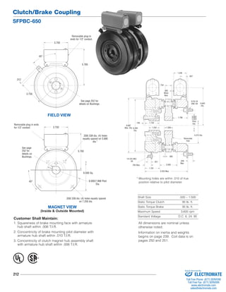
This document provides specifications for the SFPBC-650 clutch/brake coupling, including: - Shaft size range of 0.500-1.500 inches and maximum speed of 3,600 rpm. - Static torque ratings of 95 lb-ft for both the clutch and brake. - Standard voltage options of 6, 24, and 90V DC. - Dimensions and mounting details for the various components.

Recommended
Recommended
More Related Content
What's hot
What's hot (20)
Similar to SFPBC-650 Clutch/Brake Coupling Details
Similar to SFPBC-650 Clutch/Brake Coupling Details (13)
More from Electromate
More from Electromate (20)
Recently uploaded
Recently uploaded (20)
SFPBC-650 Clutch/Brake Coupling Details
- 1. Clutch/Brake Coupling SFPBC-650 5/16-18 UNC-3A 1/4-20 UNC- Reversible 2A .546 2.093 3.750 .358/.338 dia. (4) holes equally spaced on 3.688 See page 252 for details on Bushings. Shaft Size .500 – 1.500 Static Torque Clutch 95 lb. ft. Static Torque Brake 95 lb. ft. Maximum Speed 3,600 rpm Standard Voltage D.C. 6, 24, 90 Customer Shall Maintain: 1. Squareness of brake mounting face with armature hub shaft within .006 T.I.R. 2. Concentricity of brake mounting pilot diameter with armature hub shaft within .010 T.I.R. 3. Concentricity of clutch magnet hub assembly shaft with armature hub shaft within .006 T.I.R. 212 .734 .156 4.375 Dia. .937 .421 .765 Max. Max Hub .062 1.781 5.203 Max. 6.687 Max. Dia. 6.359 Dia. 1.750 1.250 1.000 1.796 2.822 2.820 Pilot Dia. 4.640 Dia. 1.546 .062 When New FIELD VIEW See page 252 for details on Bushings. 45° 5.765 3.750 .312 3.750 Removable plug-in ends for 1/2" conduit. * Mounting holes are within .010 of true position relative to pilot diameter. .358/.338 dia. (4) holes equally spaced MAGNET VIEW on 7.250 dia. (Inside & Outside Mounted) Removable plug in ends for 1/2" conduit. 5.765 dia.* 6.500 Sq. 8.000/7.998 Pilot Dia. 45° ® U L All dimensions are nominal unless otherwise noted. Information on inertia and weights begins on page 239. Coil data is on pages 250 and 251. Sold & Serviced By: ELECTROMATE Toll Free Phone (877) SERVO98 Toll Free Fax (877) SERV099 www.electromate.com sales@electromate.com
- 2. Clutch/Brake Coupling SFPBC-650 213 How to Order: 1. Specify Voltage for Item 1 and Item 8. 2. Specify Bore Size for Item 2 and Item 5. 3. Specify Inside Mounted for Item 8A and Outside Mounted for Item 8B. 4. See Controls Section. Example: SFPBC-650 per I-25751 - 90 Volt, 1" Bore These units, when used in conjunction with the correct Warner Electric conduit box, meet the standards of UL508 and are listed under guide card #NMTR, file #59164. These units are CSA certified under file #LR11543 Drawing I-25751 1( Shipped Assembled) 10 11 1-1 1-2 1-3 1-4 1-4-1 1-5 1-9 1-6 2 1-7 1-8 3 11 8A 11 8A-1 8B-1 9 8B 9 7 4 6 6 5 Item Description Part Number Qty. 1 Field & Rotor Assembly 1 6 Volt 5207-452-002 24 Volt 5207-452-005 90 Volt 5207-452-004 1-1 Retainer Ring External 748-0004 1 1-2 Retainer Ring Internal 748-0104 1 1-3 Ball Bearing 166-0104 1 1-4 Field Assembly 1 6 Volt 5281-451-002 24 Volt 5281-451-004 90 Volt 5281-451-005 1-4-1 Terminal Accessory 5311-101-001 3 1-5 Rotor Hub 540-0614 1 1-6 Rotor Assembly 5281-751-001 1 1-7 Lockwasher 950-0355 4 1-8 Capscrew 797-0083 4 1-9 Reverse Mounting Accessory 5201-101-005 1 2 Bushing* 1 1/2" to 1-1/2" Bore 180-0002 to 180-0018 3 Armature Clutch 5281-111-002 1 4 Armature Hub 5207-541-002 1 5 Bushing* 1/2" to 1-5/8" Bore 180-0326 to 180-0344 1 6 Autogap Accessory 5181-101-010 8 7 Armature - Brake 5281-111-002 1 8A Magnet - Inside Mounted 1 6 Volt 5369-631-003 24 Volt 5369-631-006 90 Volt 5369-631-005 Item Description Part Number Qty. 8A-1 Terminal Accessory 5311-101-001 2 8B Magnet - Outside Mounted 1 6 Volt 5369-631-009 24 Volt 5369-631-012 90 Volt 5369-631-011 8B-1 Terminal Accessory 5311-101-001 2 9 Mounting Accessory 5321-101-002 1 †10 Torque Arm Accessory 5207-101-003 1 11 Conduit Box 5200-101-010 3 *See page 252 for specific part numbers. Refer to Service Manual P-202. †Optional – not included in price. Sold & Serviced By: ELECTROMATE Toll Free Phone (877) SERVO98 Toll Free Fax (877) SERV099 www.electromate.com sales@electromate.com