Thomson Linear RoundRail Continuous Support 1PB Specs
Rsf electronik ms82_catalog
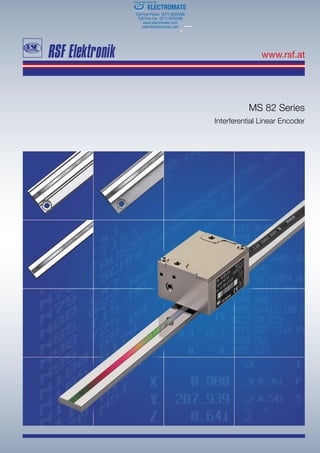
1. Interferential Linear Encoder
MS 82 Series
ELECTROMATE
Toll Free Phone (877) SERVO98
Toll Free Fax (877) SERV099
www.electromate.com
sales@electromate.com
Sold & Serviced By:
2. 02
The scale consists of a glass carrier and a reflection-type
phase grating. The scanning reticle acts as transmission phase
grating.
The light beam, produced by an LED and collimated by a lens,
is deflected by prisms and the phase grating of the reticle
in different directions.
After reflection and diffraction at the scale grating,
the different beams, depending on the change of position
phase shifted, interfere after passing the reticle again.
In this way 2 by 90° shifted, sinusoidal measuring signals
are produced. Using this interferential measuring principle,
one signal period equals half of the scale.
REFLECTION-TYPE PHASE GRATING
TECHNICAL DATA
Reading head: 4 µm signal period , accuracy grades: ±3 µm/m
Scale unit:
- Glass scale: (α ≈ 8.5 x 10⁻⁶
/K)
- Glass ceramic scale: (α ≈ 0 x 10-6
/K)
Grating pitch: 8 µm phase grating (4 µm signal period)
Max. measuring length: Glass: 3140 mm,
Glass ceramic: 1840 mm (longer on request)
Reference mark (RI):
Any position within measuring length.
RI reapeatable only from one direction.
Features: 2 switch tracks (S1, S2)
for individual special functions (reflection light barrier)
The desired switch positions are determined by the customer
with adhesive cover tapes.
- Version 1: TTL output (active high)
- Version 2: open collector output (aktive high impedance)
- Version 3: TTL output (active low)
- Version 4: open collector output (active low)
RoHS-conformity:
The Linear Encoders of the MS 82 series comply with
the guideline of the RoHS-directive 2011/65/EU on
the restriction of the use of certain hazardous substances
in electrical and electronic equipment.
Scale unit: version with glass scale or glass ceramic scale with phase grating
Scale
model
Output
signals
System resolution
[µm]
Integrated
interpolation
Max. velocity
[m/s]
Max. output
frequency [kHz]
MS 82.00 1 Vpp
je nach externer
Unterteilung
-- 0.8* 200
Edge separation
amin
MS 82.70 0.1 times10 0.8 100 ns
MS 82.40 0.05 times20 0.48 100 ns
MS 82.50 0.04 times25 0.38 100 ns
MS 82.80 0.02 times50 0.19 100 ns
MS 82.90 0.01 times100 0.096 100 ns
Features:
Two switch tracks for individual special functions
Non-contact reflective scanning
For high traversing speed
Small dimensions
Any position of the reference mark
within measuring length
Integrated subdividing: Up to times 100
Scale unit: Glass scale or glass ceramic scale
with phase grating
Max. measuring length: 3140 mm
* on request: up to 1.5 m/s
ELECTROMATE
Toll Free Phone (877) SERVO98
Toll Free Fax (877) SERV099
www.electromate.com
sales@electromate.com
Sold Serviced By:
3. 03
MS 82 BO, BK, GO, GK
Version BO: Glass ceramic scale
Version BK: Glass ceramic scale with adhesive tape
Version GO: Glass scale
Version GK: Glass scale with adhesive tape
On request: Other versions with glass- or glass ceramic scale on steel- or aluminum carrier
Weight (approx.):
Version BO: 65 g/m
Version BK: 70 g/m
Version GO: 95 g/m
Version GK: 100 g/m
+ 38 g (reading head without cable)
ELECTROMATE
Toll Free Phone (877) SERVO98
Toll Free Fax (877) SERV099
www.electromate.com
sales@electromate.com
Sold Serviced By:
4. A-5121 Tarsdorf +43 (0)6278 / 8192-0 FAX +43 (0)6278 / 8192-79 e-mail: info@rsf.at internet: www.rsf.at
OUTPUT SIGNALS
PIN ASSIGNMENT
Test* = analog signal switch-over for setup APG 801
By applying +5 V to the test pin, the test signals
(sinusoidal micro-current signals 11 µApp)
are switched to the output connector.
Test** = analog signal switch-over for setup via APG 801 1 Vpp
By applying +5 V to the test pin, the NOT corrected 1 Vpp signals
are switched to the output connected.
*** Versions without switch signals (version 0) = nc
Sensor: The sensor-pins are bridged in the chassis with the particular power supply.
Pin assignment
(view on pins)
APG 801/APG 801 1 VPP ELECTRONIC SIGNAL TEST/SET-UP BOX
Date 04/2013 Art.Nr. 784839-21 Doc.Nr. D784839-00-A-21 Technical adjustments in reserve!
Pin 1 2 3 4 5 6 7 8 9 10 11 12 13 14 15
Sinusoidal
voltage signals 1 Vpp
test** 0 V
sensor
nc RI A2 A1 +5 V
sensor
+5 V 0 V S1*** S2*** RI A2 A1 shield
Square-wave signals
via Line Driver
test* 0 V
sensor
US RI T2 T1 +5 V
sensor
+5 V 0 V S1*** S2*** RI T2 T1 shield
Connector AWS 15-pin
Sinusoidal voltage signals 1 Vpp Square-wave signals „differential“ Error signal
ELECTROMATE
Toll Free Phone (877) SERVO98
Toll Free Fax (877) SERV099
www.electromate.com
sales@electromate.com
Sold Serviced By:

![02
The scale consists of a glass carrier and a reflection-type
phase grating. The scanning reticle acts as transmission phase
grating.
The light beam, produced by an LED and collimated by a lens,
is deflected by prisms and the phase grating of the reticle
in different directions.
After reflection and diffraction at the scale grating,
the different beams, depending on the change of position
phase shifted, interfere after passing the reticle again.
In this way 2 by 90° shifted, sinusoidal measuring signals
are produced. Using this interferential measuring principle,
one signal period equals half of the scale.
REFLECTION-TYPE PHASE GRATING
TECHNICAL DATA
Reading head: 4 µm signal period , accuracy grades: ±3 µm/m
Scale unit:
- Glass scale: (α ≈ 8.5 x 10⁻⁶
/K)
- Glass ceramic scale: (α ≈ 0 x 10-6
/K)
Grating pitch: 8 µm phase grating (4 µm signal period)
Max. measuring length: Glass: 3140 mm,
Glass ceramic: 1840 mm (longer on request)
Reference mark (RI):
Any position within measuring length.
RI reapeatable only from one direction.
Features: 2 switch tracks (S1, S2)
for individual special functions (reflection light barrier)
The desired switch positions are determined by the customer
with adhesive cover tapes.
- Version 1: TTL output (active high)
- Version 2: open collector output (aktive high impedance)
- Version 3: TTL output (active low)
- Version 4: open collector output (active low)
RoHS-conformity:
The Linear Encoders of the MS 82 series comply with
the guideline of the RoHS-directive 2011/65/EU on
the restriction of the use of certain hazardous substances
in electrical and electronic equipment.
Scale unit: version with glass scale or glass ceramic scale with phase grating
Scale
model
Output
signals
System resolution
[µm]
Integrated
interpolation
Max. velocity
[m/s]
Max. output
frequency [kHz]
MS 82.00 1 Vpp
je nach externer
Unterteilung
-- 0.8* 200
Edge separation
amin
MS 82.70 0.1 times10 0.8 100 ns
MS 82.40 0.05 times20 0.48 100 ns
MS 82.50 0.04 times25 0.38 100 ns
MS 82.80 0.02 times50 0.19 100 ns
MS 82.90 0.01 times100 0.096 100 ns
Features:
Two switch tracks for individual special functions
Non-contact reflective scanning
For high traversing speed
Small dimensions
Any position of the reference mark
within measuring length
Integrated subdividing: Up to times 100
Scale unit: Glass scale or glass ceramic scale
with phase grating
Max. measuring length: 3140 mm
* on request: up to 1.5 m/s
ELECTROMATE
Toll Free Phone (877) SERVO98
Toll Free Fax (877) SERV099
www.electromate.com
sales@electromate.com
Sold Serviced By:](data:image/gif;base64,R0lGODlhAQABAIAAAAAAAP///yH5BAEAAAAALAAAAAABAAEAAAIBRAA7)