1. 28
Flange Mounted Spring Applied Brakes – Type FSB
Spring Applied
Friction Brakes
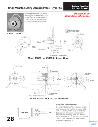
Customer Shall Maintain:
the perpendicularity of the mounting surface
with respect to the shaft not to exceed .005
inch T.I.R. at a diameter equal to the brake
body outside diameter; the concentricity
between the mounting holes and the shaft
not to exceed .010 T.I.R. for sizes 001-015 and
.020 T.I.R. for sizes 035-100. Refer to instruc-
tion manual #040-10110.
Inertia Dynamics type FSB brakes
are designed to decelerate or hold
inertial loads when the voltage is
turned off. These brakes can be
mounted to a bulkhead or motor.
J Pitch
Circle Dia.
30°
A
B
C
H
Pilot Dia.
G Dia. F M D Dia.
Set Screws
(1 – #4-48 For FSB001 Models;
2 – #6-32 For FSB003 Models;
90° Apart)
K Dia. (3 Places)
E Max. Dia.
Hub Assembly
Pressure Plate
Friction Disc
Clapper Plate
Field Assembly
Air Gap (Set By Inertia Dynamics)
K Dia. (4) Places
.625
Hex. Nom
J Pitch Circle Dia.
Model FSB001 or FSB003 - Square Drive
Model FSB007 or FSB015 - Hex Drive
A
B
C
H D
F
E
Max. Dia.
N
G Ref.
Hub Assembly
Pressure Plate
Friction Disc
Field Assembly
.225
Hub Position.205
Clapper Plate
Air Gap (Set By Inertia Dynamics)
45°
M I
Y
(2) Set Screws
90° Apart
.325
.312
(4) Places
X
L
FSB001 Shown
PRIME MOVER LOAD
See page 30 for
dimensional information
ELECTROMATE
Toll Free Phone (877) SERVO98
Toll Free Fax (877) SERV099
www.electromate.com
sales@electromate.com
Sold & Serviced By:
2. 29
Flange Mounted Spring Applied Brakes – Type FSB
Spring Applied
Friction Brakes
Model FSB007 or FSB015 – Zero Backlash
Model FSB035, FSB050 or FSB100 – Zero Backlash
K Dia. (4) Places
J Pitch
Circle Dia.
A
B
C
G Dia. D Dia.H Dia.
N
.225
.205
Hub Position
E Dia.F
Air Gap (Set By Inertia Dynamics)
Air Gap (Set By
Inertia Dynamics)
Y
M Dia.
X
I
45°
(2) Set Screws
90° Apart
.325
.312
(4) Places
K Dia. (4) Places
J Pitch
Circle Dia.
H Dia.
A
C
F
B
N
G Dia. D Dia.
E Dia.
X
Y
M Dia.
15°
(2) Set Screws
90° Apart
FSB035 Shown
FSB007 Shown
See page 30 for
dimensional information
Model FSB035, FSB050,or FSB100 - Hex Drive
(2) Set Screws
90° Apart
K Dia. (4) Places
J Pitch
Circle Dia.
H
A
B
C
N
E
L
X
Y
15°
D
F
Alternate Keyway
Location for 3/4
Bore Only
MG
Hub Assembly
Pressure Plate
Friction Disc
Clapper Plate
Field Assembly
Air Gap (Set By Inertia Dynamics)
ELECTROMATE
Toll Free Phone (877) SERVO98
Toll Free Fax (877) SERV099
www.electromate.com
sales@electromate.com
Sold & Serviced By:
3. 30
Flange Mounted Spring Applied Brakes – Type FSB
Spring Applied
Friction Brakes
INERTIA LB. – IN.2
ARMATURE & HUB
ASSEMBLY
STATIC
MODEL TORQUE SQUARE OR ZERO WGT.
NO. LB. – IN. HEX DRIVE BACKLASH OZ.
FSB001 1 .0004 N.A. 2
FSB003 3 .0017 N.A. 3
FSB007 7 .0133 .0176 15
FSB015 15 .0133 .0176 16
FSB035 35 .084 .1733 33
FSB050 50 .084 .1733 36
FSB100 100 .205 N.A. 64
MODEL
90 VDC 24 VDC 12 VDC 120 VAC
NO. AMPS OHMS AMPS OHMS AMPS OHMS AMPS OHMS
FSB001 .051 1880 .220 117 .430 30 .044 N.A.
FSB003 .041 2177 .182 132 .353 34 .050 N.A.
FSB007 .059 1520 .247 97.3 .477 25.1 .045 N.A.
FSB015 .098 922 .369 65.1 .719 16.7 .077 N.A.
FSB035 .093 964 .394 61.0 .755 15.9 .073 N.A.
FSB050 .194 465 .717 33.5 1.54 7.75 .140 N.A.
FSB100 .180 501 .707 34 1.41 8.5 .142 N.A.
Mechanical Electrical
Lead wire is UL recognized style 1430 or 1015, 22 gage.
Insulation is .064Љ O.D. on 001 & 003 units; .095Љ O.D. on 007, 015, 035, 050 & 100 units.
NOTES:
Hex Drive – FSB
1. For sizes 001 and 003, position hub .010-
.020 inches back from friction disc with coil
de-energized.
2. For sizes 007 and larger, position hub .010-
.030 inches back from clapper plate with coil
de-energized.
3. 1
/2 inch bore not available for sizes 007 and
015.
Zero Backlash – FSB
1. Position hub to run freely with coil energized
taking care to center the friction disc
between the clapper and pressure plate.
M BORES & KEYWAYS
MODEL HUB A B C D E F G H I J K L N NOMINAL KEYWAY
NO. STYLE MAX. MAX. NOM. MAX. MAX. MIN. REF. MAX. ± .500 NOM. MIN. NOM. MAX. BORE X Y
1
/8
FSB001 Square Drive .890 .710 .072 .510 1.485 .320 .280 1.375 12.0 1.180 .113 3
/8 N.A. 3
/16 SET SCREWS ONLY
1
/4
3
/16
FSB003 Square Drive 1.060 .870 .115 .755 1.910 .380 .410 1.752 12.0 1.545 .113 9
/16
1
/4
SET SCREWS ONLYN.A. 5
/16
3
/8
Hex Drive 1.400 1.200 1.255 .722 2.465 .605 .781 2.436 12.0 2.125 .170 5
/8 .120
1
/4 .0625 – .0655 .285 – .290
5
/16 .0625 – .0655 .347 – .352
FSB007 3
/8 .094 – .097 .417 – .427
Zero Backlash 1.400 1.200 1.255 .955 2.465 .450 .781 2.436 12.0 2.125 .170 N.A. — 1
/2* .125 – .128 .560 – .567
Hex Drive 1.400 1.200 1.255 .722 2.465 .605 .781 2.436 12.0 2.125 .170 5
/8 .120
1
/4 .0625 – .0655 .285 – .290
5
/16 .0625 – .0655 .347 – .352
FSB015 3
/8 .094 – .097 .417 – .427
Zero Backlash 1.400 1.200 1.255 .955 2.465 .450 .781 2.436 12.0 2.125 .170 N.A. — 1
/2* .125 – .128 .560 – .567
Hex Drive 2.110 1.920 1.960 1.000 3.010 .580 .891 3.500 18.0 3.125 .200 11
/8 .142
3
/8 .094 – .097 .417 – .427
1
/2 .125 – .128 .560 – .567
FSB035 5
/8 .1885 – .1905 .709 – .716
Zero Backlash 2.230 1.915 1.998 1.625 3.010 .730 .891 3.500 18.0 3.125 .200 N.A. — 3
/4 .1885 – .1905 .836 – .844
Hex Drive 2.110 1.920 1.960 1.000 3.010 .580 .891 3.500 18.0 3.125 .200 11
/8 .142
3
/8 .094 – .097 .417 – .427
1
/2 .125 – .128 .560 – .567
FSB050 5
/8 .1885 – .1905 .709 – .716
Zero Backlash 2.230 1.915 1.998 1.625 3.010 .730 .891 3.500 18.0 3.125 .200 N.A. — 3
/4 .1885 – .1905 .836 – .844
1
/2 .125 – .128 .560 – .567
FSB100 Hex Drive 2.320 2.080 2.100 .975 4.000 .555 1.188 5.250 18.0 4.750 .216 11
/2 .210 5
/8 .1885 – .1905 .709 – .716
3
/4 .1885 – .1905 .836 – .844
Dimensions
*1
/2Љ bore available in Zero Backlash only.
See page 3 for ordering information
ELECTROMATE
Toll Free Phone (877) SERVO98
Toll Free Fax (877) SERV099
www.electromate.com
sales@electromate.com
Sold & Serviced By:
4. 3
Ordering Information
Electromagnetic
Friction Clutches & Brakes
Spring Applied Brakes
PART NUMBERING SYSTEM FOR PRODUCTS ON PAGES 3 TO 35 OF THIS CATALOG
A A B B - C D E F
DIGIT DIGIT MODEL NO.
1 7 FSB
1 9 FSBR
2 1 FSBR
(MANUAL
RELEASE)
0 1 SL
0 3 BSL
0 5 FL
0 7 SO
0 9 FO
1 1 FB
1 3 SLB
1 5 SOB
1 8 SAB
DIGIT DIGIT SIZE
0 1 001
0 2 003
0 3 007
0 4 015
0 5 035
0 6 050
0 7 100
0 8 200
0 9 08
1 0 11
1 1 15
1 2 17
1 3 19
1 4 22
1 5 26
1 6 30
1 7 42
1 8 20
1 9 90
2 1 180
2 3 400
2 5 1200
DIGIT VOLTS
1 90 VDC
2 24 VDC
3 12 VDC
4 120 VAC
DIGIT BORE
1 1
/8
2 3
/16
3 1
/4
4 5
/16
5 3
/8
6 1
/2
7 5
/8
8 3
/4
9 7
/8
0 1
11 1 1
/8
12 1 1
/4
13 1 3
/8
14 1 1
/2
DIGIT DRIVE
1 ZERO
BACKLASH
2 HEX/SQUARE
3 DYNAMIC
(MANUAL RELEASE
BRAKE ONLY)
4 STATIC
(MANUAL RELEASE
BRAKE ONLY)
5 SPLINE
DIGIT CONNECTION
1 LEAD
WIRES
2 SCREW
TERMINALS
3 SWITCH
(MANUAL RELEASE
BRAKE ONLY)
4 CONDUIT
BOX
How To Order
A. Select the model number from the product guide.
B. Select the size of the clutch or brake.
C. Select the voltage.
D.Select the bore diameter.
E. For all power-on clutches and brakes, select 1. For model FSBR and SAB-20,
& 90, select 2. For model FSB spring applied brakes, select 1 or 2. For man-
ual release brakes, select 3 or 4. For SAB-180, 400, & 1200, select 5.
F. For all clutches and brakes, refer to the product guide and specify 1 or 2.
For manual release brakes, if a switch is desired, select 3, otherwise use a 1.
Example
SL11 clutch, 24 volts, 1
/4Љ bore
Part No. 0110-2311
FSB050 brake, 90 volts, 3
/8Љ bore, Hex drive
Part No. 1706-1521
ELECTROMATE
Toll Free Phone (877) SERVO98
Toll Free Fax (877) SERV099
www.electromate.com
sales@electromate.com
Sold & Serviced By: