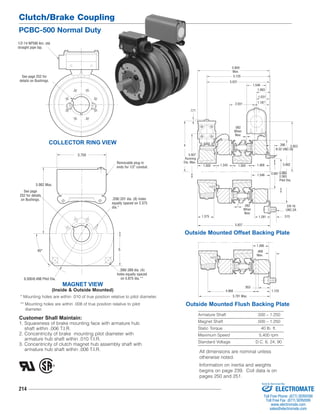
1. Clutch/Brake Coupling
PCBC-500 Normal Duty
1/2-14 NPSM Am. std.
straight pipe tap.
See page 252 for
details on Bushings.
See page
252 for details
on Bushings.
214
1.546
1.093
1.031
5.859
Max.
5.125
5.031
2.031
4 3.953
1.500 1.343 1.500 1.468
1.546
1.375 1.281
8-32 UNC-3A
2.065
2.063
Pilot Dia.
4.968
5.781 Max.
1.390
Armature Shaft .500 – 1.250
Magnet Shaft .500 – 1.250
Static Torque 40 lb. ft.
Maximum Speed 5,400 rpm
Standard Voltage D.C. 6, 24, 90
COLLECTOR RING VIEW
3.750
Customer Shall Maintain:
1. Squareness of brake mounting face with armature hub
shaft within .006 T.I.R.
2. Concentricity of brake mounting pilot diameter with
armature hub shaft within .010 T.I.R.
3. Concentricity of clutch magnet hub assembly shaft with
armature hub shaft within .006 T.I.R.
5.062
2.687
.390
.062
When
New
1.187
.171
.062
When
New
5.937
3/8-16
UNC-2A
.515
5.937
Running
Dia. Max.
Outside Mounted Offset Backing Plate
.953
.468
Max.
1.125
Outside Mounted Flush Backing Plate
MAGNET VIEW
(Inside & Outside Mounted)
Removable plug in
ends for 1/2" conduit.
5.062 Max.
45° 5
6.500/6.498 Pilot Dia.
.208/.201 dia. (8) holes
equally spaced on 2.375
dia.*
.399/.389 dia. (4)
holes equally spaced
on 5.875 dia.**
* Mounting holes are within .010 of true position relative to pilot diameter.
** Mounting holes are within .008 of true position relative to pilot
diameter.
All dimensions are nominal unless
otherwise noted.
Information on inertia and weights
begins on page 239. Coil data is on
pages 250 and 251.
Sold & Serviced By:
ELECTROMATE
Toll Free Phone (877) SERVO98
Toll Free Fax (877) SERV099
www.electromate.com
sales@electromate.com
2. Clutch/Brake Coupling
PCBC-500 Normal Duty
215
Drawing I-25547
11
How to Order:
1. Specify Bore Size for Item 3 (two shafts).
2. Specify Voltage for Item 4 and Item 10A, 10B or 10C.
3. Specify Inside Mounted for Item 10A and Outside
Mounted (Offset) for Item 10B or Outside Mounted
(Flush) for Item 10C.
4. See Controls Section.
Example:
PCBC-500 Clutch Brake Coupling per I-25547 - 90 Volt,
Inside Mounted, 1" Bore
These units meet the standards of UL508 and are listed
under guide card #NMTR2, file #59164. These units are
CSA certified under file #LR11543.
1
(Shipped
Assembled)
2
2-1
1-1
1-2
3
4
4-1
5
6
8
7
6
3
9A
10A
10A-1
9B
11
10B-1
10C-1
10B
10C
Item Description Part Number Qty.
1 Magnet Hub 5300-541-001 1
1-1 Collector Ring 5300-749-001 1
1-2 Collector Ring Mounting
Accessory 5300-101-002 1
2 Brushholder 5300-178-001 1
2-1 Brush 176-0001 4
3 Bushing* 2
1/2" - 1/4" Bore 180-0116 to 180-0128
4 Magnet, Clutch 1
6 Volt 5300-631-002
24 Volt 5300-631-003
90 Volt 5300-631-005
4-1 Terminal Accessory 5311-101-001 1
5 Mounting Accessory 5102-101-001 2
6 Armature 5300-111-002 2
7 Autogap Accessory 5200-101-009 6
8 Armature Hub 5300-541-004 1
9A Mounting Accessory - I.M. 5102-101-001 2
9B Mounting Accessory - O.M. 5300-101-008 1
10A Magnet - I.M. 1
6 Volt 5300-631-002
24 Volt 5300-631-003
90 Volt 5300-631-005
10A-1 Terminal Accessory 5311-101-001 1
Item Description Part Number Qty.
10B Magnet - O.M. - Offset 1
90 Volt 5300-631-014
10B-1 Terminal Accessory 5311-101-001 1
10C Magnet - O.M. - Flush 1
6 Volt 5300-631-009
24 Volt 5300-631-010
90 Volt 5300-631-011
10C-1 Terminal Accessory 5311-101-001 1
11 Conduit Box 5200-101-010 1
*See page 252 for specific part numbers.
Refer to Service Manual P-203.
Sold & Serviced By:
ELECTROMATE
Toll Free Phone (877) SERVO98
Toll Free Fax (877) SERV099
www.electromate.com
sales@electromate.com