Crane Gearbox Helical/Planetary train
•
0 likes•671 views

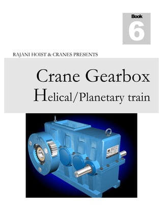
This is a 3 stage helical gearbox with a planetary gear attached in final stage. Helical Gear box could be 35:1 ratio to 120: 1 Ration possible for minimum 25Kw to 5 Kw power rating while final stage is 3.3 Ratio, totally 115:1 to 375:1ratio gearbox is possible. The planetary gear RIM gear should be attached in to the drum for final torque delivery. Total Gearbox Center Distance is 550mm

Recommended
More Related Content
What's hot
What's hot (20)
Similar to Crane Gearbox Helical/Planetary train
Similar to Crane Gearbox Helical/Planetary train (20)
Recently uploaded
Recently uploaded (20)
Crane Gearbox Helical/Planetary train
- 1. RAJANI HOIST & CRANES PRESENTS Crane Gearbox Helical/Planetary train Book 6
- 2. This is a promotional package, Strictly Not for Commercial purpose M U L T I S T A G E H E L I C A L C U M P L A N E T A R Y D E S I G N , C A L C U L A T I O N S & A P P L I C A T I O N Crane duty gearbox Design proposal DOUBLE GEAR Transmission Elements Powered by Double Gear transmission elements #7 Muthumari chetty street. Mannady,Broadway,Chennai, INDIA Mob +91-9791222047 E-mail: ceo.doublegear@gmail.com, www.doublegear.co.in Over 20 years, DOUBLE GEAR has earned a nationally recognized reputation for expertise in power transmission engineering and automation, cranes, hoist and crane duty modular gearbox design would helps engineers and manufacturers to construct robust infrastructures without any complications and completely tested & trusted.
- 3. i WELCOME Good Morning, I am Nagarajan from INDIA doing material handling equipment manufacturing, supplying and exporting, I always used to dream something innovative way to develop concepts and ideas in my field of engineering So for I have designed various components for the cranes, For example gearboxes, Electrical wire rope Hoists, electrical safety circuits and accessories. Among these, my Drum rope guide design, Cross pulling prevention Mechanisms, hypocycloid limit switches are very famously accepted in my colleagues organizations This time I have developed new design for gearboxes, It is very innovative idea for carne applications particularly for driving Rope drum application. Normally Drums are driven by Center shaft/ bull gear with pinion, which consume more power and make the gearbox stressful. The reason is the driven element is getting load from outer circumference, while driving element is laboring from center of the load. This might make the torque depletion By arranging The final stage Planetary method, The generated torque is evenly distributed to the all parts of the rotating part with Ring gear attached inside the drum and more safe from single shaft/pinion failure Comparing to conventional method by attaching Bull Gear with pinion, it is very compact and efficient , I would like to share my concept with you for further developments and improvements. I like to hear your valuable opinions, please share if you like this Thanks Nagarajan.B +91 9791222047 ( CEO) rajanihoistandcranes@gmail.com Thursday, May 9, 2019
- 4. ii SECTION 1 Basic idea Picture showing how the Gear box has been assembled This is a 3 stage helical gearbox with a planetary gear attached in final stage. Helical Gear box could be 35:1 ratio to 120: 1 Ration possible for minimum 25Kw to 5 Kw power rating while final stage is 3.3 Ratio, totally 115:1 to 375:1 ratio gearbox is possible. The planetary gear RIM gear should be attached in to the drum for final torque delivery. Total Gearbox Center Distance is 550mm
- 5. iii SECTION 2 Data Sheet of the helical part Picture shows the Data Sheets of the Helical Gears manufacturing details This data sheets shows the design, calculations and Gear manufacturing details. The total gearbox design follows DIN 3990 method B drafting. Gearbox has been split in to 140+190+220=550mm. Blank OD, Gear cutting Details and Quality inspection details are given. Please see below topic for further details
- 6. iv SECTION 3 Gear Design Details A close look of the Gear Finishing The strength calculation (tooth fracture, pitting, wear and temperature safeties) The strength calculations are carried out according to norms (DIN 3990, ISO 6336, etc.). it is maintained 15 Degree helix left for Gears and The same Right angle for pinion to balanced operation Furthermore, it is necessary to have some knowledge about gear technology, as you have to interpret the results. In general, one can say that, according to DIN 3990, part 11 (Industrial gear boxes), a safety factor for the root of 1.4 and a safety factor for Hertzian stress of 1 is sufficient. But we maintain 1.5 Service factors
- 7. v • Application Factor (service factor) The application factor considers uncertainties in load and impacts. It is always larger than or equal as 1. A hint for the factor can be found in the following table and more comprehensive information is available in DIN 3990, DIN 3991 or ISO 6336. Working condition of the Driving Force Working condition of the driven machine Uniform Moderate Medium Heavy Uniform 1 1.25 1.5 1.75 Moderate Impact 1.1 1.35 1.6 1.85 Medium Impact 1.25 1.5 1.75 2 Heavy Impact 1.5 1.75 2 2.25 • Tooth thickness deviations (backlash) The geometry of the gears is calculated for backlash free state. To prevent the gears from jamming, the tooth thickness is manufactured slightly smaller (than the theoretical value). This decrease of the tooth thickness is called tooth thickness deviation. The upper tooth thickness deviation represents the maximal allowable thickness and the lower the minimal. Tolerance according DIN 3967 Centre Distance Optimizing the centre distance regarding balanced sliding At a predetermined addendum modification factor for gear, the centre distance is calculated with this option, to compensate for balanced sliding of the gear pair. The calculation is carried out with automatic tip radius reduction according DIN 3960 Tolerance according to ISO (z.B. js6)
- 8. vi SECTION 4 Gear Quality Control method Picture shows how Gears and pinions are meshing All gears and pinions are having Addendum modification factor for balances sliding for noiseless operation.the proposal represents the addendum modification required for balanced specific sliding between pinion and wheel While Gears and Pinions are manufacturing, Span measurement over the no of teeth is strictly maintained according to the Addendum modifications and Center Distance. If the gears are designed for profile grounding,
- 9. vii A close look of the Specific Sliding Specific sliding is shown as condition of sliding where engaged flanks slides to transfer the rotation except area of pitch point Sliding velocity is the relative velocity in a transverse plane of a common contact point between mating gear teeth. As shown in Figure it is the vectorial difference between the two rolling velocities that are tangential to the tooth profiles and perpendicular to the line of action. See references AGMA ( 2005) and ISO ( 2007) for gear nomenclature and definitions of terms.
- 10. viii SECTION 5 How the Drum and Gearbox is connected Picture Shown Rope drum connected in to the Gearbox The planetary Rim gear is fastened in to the Drum inside. While the Carrier is fixed with Gearbox Housing, The planet Gears will rotate ring gears subsequently drum will rotate on the speed of Sun gear to Rim Gear ratio Drum Rotation always Same direction to Motor Shaft rotation Due to 3 stage and Planetary gears
- 11. ix Picture Shown Open View Advantages: • Drum Circumference Evenly get Torque • Easy to maintenance For Serving • Consuming Less Power • More Compact for larger size drums Disadvantages (I feel some improvements requires) 1. More moving parts 2. Unique Ring gears required for Different OD Drums 3. Manufacturing Cost Slightly increased
- 12. x The actual performances of this Design could be justified after manufactured and tested, Engineers, amateurs and friends Please give your suggestions and opinions for improvements I have future plans for implementing energy saving alpha starting gearboxes, Rapide Speed Gearboxes and compressors for Cross travel also. Definitely I would share my experience. Stay touched Please Note: This a prototype proposal. Still not verified & tested, If you like it, Please request me, I will send you manufacturing Drawings and specifications. Try to do improve yourself and share your experience & knowledge Thanks For Reading Nagarajan CEO, Rajani Hoist and cranes BANGALORE , INDIA Saturday, May 11, 2019