SlideShare a Scribd company logo
1 of 91
Download to read offline
20MCT31 - DATA COMMUNICATION NETWORKS
UNIT – 1
NETWORK FUNDAMENTALS
DATA COMMUNICATION:
● Data communication is the exchange of data between two devices via some form of
transmission medium such as cable.
● Data communication to occur, the communicating devices must be part of
communicating system made up of combination of hardware and software.
EFFECTIVE COMMUNICATION:
The effectiveness of data communication depends on
● Delivery
● Accuracy
● Timeliness
● Jitter
COMPONENTS OF DATA COMMUNICATION:
Message: The message is the information to be communicated in the form of text, number,
pictures, images, audio, video and etc....
Sender: The sender is the device that sends message via computer, telephone handset,
workstation and so on....
Receiver: The receiver is the device that receives the message through computer,
workstation, telephone handset and so on....
Transmission medium: The transmission medium is the path in which a message travels
from sender to receiver by twisted pair wire, fiber-optic cable,
coaxial cable and radio waves.
Protocol: A protocol is a set of rules that govern data communication. Without protocol two
devices may be connected but not communicate.
DATA FLOW:
Simplex:
● Simplex mode is unidirectional communication where the sender sends the data, but the
sender cannot receive the data.
● Usage of one channel for transmission of data and also provides less performance than half
duplex and full duplex. Eg: Keyboard and Monitor.
Half duplex:
● Half duplex is two-way directional communication but one at a time, that is sender can
send the data also receive the data one at a time.
● Usage of one channel for transmission of medium and provides less performance than full
duplex. Eg: Walkie-Talkies
Full duplex:
● Full duplex is a two-way directional communication, where the sender can send the data
and receive the data simultaneously.
● Usage of two channels for transmission of data and provides better performance than
simplex and half duplexes: Telephone.
NETWORK CRITERIA:
A network must meet a certain number of criteria,
● Performance
● Reliability
● Security
TYPES OF CONNECTION:
● Point to point connection
● Multipoint connection
PHYSICAL TOPOLOGY:
The topology of network is a geometric representation of the relationship between all
the links and the linking devices. There are 4 basic topologies possible
● Mesh
● Star
● Bus
● Ring
MESH TOPOLOGY:
It is a point-to-point connection to all devices. For n devices mesh has n(n-1)/2
physical channels.
Advantage:
● Each and every connection can carry its own data load.
● It is robust.
● Faults are identified easily.
● It provides security and privacy.
Disadvantage:
● Installation and configuration are difficult.
● Cabling costs are more.
● Bulk wiring is required.
Eg: Connection of telephone regional offices need to connect to every other regional office.
STAR TOPOLOGY: In Star topology all hosts are connected to a central device, known as
hub device, using a point-to-point connection.
Advantage:
● If a single computer within the network stops working, then the rest of the network will
work normally.
● This topology is very reliable.
● Fault detection is simple because the links are identified frequently and easily.
Disadvantage:
● It needs high maintenance and resources.
● The cables utilized within the network can damage very easily.
● It mainly depends on the central hub.
Eg: High speed LAN often uses star topology.
BUS TOPOLOGY: In this topology, all the nodes are connected through a single cable
known as ‘Backbone’. If this Backbone cable is damaged the entire network breakdowns.
Advantages:
● Require less cabling compared to other topologies.
● Easy to implement for small networks.
● It is easy to expand by simply joining two cables together.
● Very cost-effective.
Disadvantage:
● This topology is very slow compared to other
● It is difficult to find the fault that occurs.
● Any fault occurs in the cable whole network become lost.
● The performance of the network decreases as traffic increases.
Eg: Traditional Ethernet LAN uses bus topology but now it becomes less popular.
RING TOPOLOGY:
Ring topology is a type of network topology in which each device is connected to two
other devices on either side an RJ-45 cable or coaxial cable.
Data is commonly transferred in one direction along the ring, known as a unidirectional
ring. The data is forwarded from one device to the next, until it reaches the intended
destination.
Advantage:
● Peer-to-peer configuration offers the best sharing of their all-linked resources.
● Performance of the speed doesn’t degrade even though we add some nodes
● It is capable to manage large number of nodes with excellent communication
Disadvantage:
● If any one computer gets down, then the whole network will be affected.
● More expensive to implement than bus topology.
● Unidirectional communication reduces performance.
NETWORK TYPES:
 Local Area Network
 Wide Area Network
PROTOCOL LAYERING:
When the communication is simple, we need only simple protocol but when the
communication is complex, we need to divide the task between different layers, so we need
protocols at each layer is known as protocol layering.
TCP/IP PROTOCOL SUITE:
TCP/IP stands for Transmission Control Protocol/Internet Protocol and is a suite of
communication protocols used to interconnect network devices on the internet. TCP/IP is also
used as a communications protocol in a private computer network.
TCP/IP specifies how data is exchanged over the internet by providing end-to-end
communications that identify how it should be broken into packets, addressed, transmitted,
routed and received at the destination.
The four layers in the TCP/IP protocol suite are:
By using logical connections, it makes us easy to understand the duty of each layer. For the
application, Transport and network layer is end to end i.e.., internet and the last two layers
(datalink and physical layer) have hop to hop i.e.., router.
Data unit created in each layer should not be changed by any router or link layer but in last
two layers the packet created by host is changed by routers not by link layer switches.
PHYSICAL LAYER:
The physical layer is responsible for carrying individual bits in a frame across the
link. The physical layer is the lowest level in TCP/IP and the communication between two
devices in the physical layer is logical communication because of the hidden layer, the
transmission medium under the
physical layer.
Two devices are connected by transmission medium, and we know that transmission
medium doesn’t carry bits. It carries optical or electrical signal. So, the bits received in a
frame from the data link layer are transformed and sent through transmission media, but we
can think that the logical unit between two physical layers in two devices is a bit.
DATA LINK LAYER:
The routers are responsible for choosing the best links. However, When the next link to
travel is determined by the routers, the data link layer is responsible for taking the datagram
and moving it across the link.
TCP/IP does not define any specific protocol for datalink layer. It supports all standard
and proprietary protocols. Any protocols that can take datagram and carry it through link
suffices for network layer. The datalink layer takes a datagram and encapsulates it in a packet
called a frame.
NETWORK LAYER:
The network layer is responsible for creating a connection between the source
computer and the destination computer. Also, the network layer is responsible for host-to-
host communication and routing packet through possible routes. The network layer on the
internet includes the main protocol, Internet Protocol that defines the format of the packet
called datagram at the network layer. IP is connectionless in that it provides no flow control,
no error control and congestion control services.
The network layer also has some auxiliary protocols that help IP in its delivery and
routing task. ICMP helps IP to report some problems when routing a packet. TGMP is
another protocol that helps IP multitasking. DHCP helps IP to get the network layer address
for a host. ARP is a protocol that helps IP to find the link layer of the host or router when its
network layer is given.
TRANSPORT LAYER:
The logical connection at the transport connection is also end to end. It is responsible
for providing services to the application layer. There are few transports layer protocols on the
Internet for specific tasks, the main protocol is TCP which is connection-oriented protocol
that establishes a logical connection between transport layer at two host before transferring
data. Another, UDP which is connectionless that transmit user datagram without creating
logical connection.
APPLICATION LAYER:
The logical connection between two application layers is end to end. The two layers
exchange messages between each other as though there were a bridge between the two layers.
Communication at the application layer is between two processes. Process to Process
communication is the duty of the application layer, as the process sends a request to another
process and receives a response.
The application layer in Internet includes many predefined protocols. HTTP is a vehicle
for accessing WWW.SMPT is the main protocol used in electronic mail.FTP is used for
transferring files from one host to another. DNS is used by another protocol to find the
network layer address of a computer.
ENCAPSULATION AND DECAPSULATION:
One of the important concepts of protocol layering on the internet is
encapsulation/decapsulation.
ENCAPSULATION AT THE SOURCE HOST:
● At the application layer the data to be exchanged is referred to as a message. A message
normally does not contain any header or trailer. The message is passed to the transport layer.
● The transport layer takes the message as the payload, the load that the transport layer
should take care of. It adds the transport layer header to the payload, which contain the
identifiers of the source and destination application program that want to communicate also
some more information that need for end-to-end delivery of the message such as error
control, flow. The result of this layer is called segment in TCP and datagram in UDP. Then
the layer passes the packet to the network layer.
● The network layer takes the transport layer packet as data and adds its own header to
payload. Also, the header contains the address of the source and destination host and some
more information. The result of this layer is called datagram and this passes to datalink layer.
● The datalink layer takes the network layer packet as data and adds its own header which
contains the link layer address of host. The result of link layer is called frame, and this is
passed to physical layer for transmission.
DECAPSULATION AND ENCAPSULATION AT THE ROUTER:
At the router we have both encapsulation and decapsulation because the router is
connected to two or more links.
● After the set of bits are delivered to the datalink layer this layer decapsulates the datagram
from the frame and passes it to the network layer.
● The network layer only inspects the source and destination address in the datagram header
and consults its forwarding table to find the next hop to which datagram is to be delivered.
The datagram layer is then passed to the data link layer of the next link.
● The datalink layer of the next link encapsulates the datagram in a frame andpasses it to the
physical layer for transmission.
DECAPSULATION AT THE DESTINATION HOST:
At the destination host each layer only decapsulates the packet received, removes the payload
and delivers the payload to the next higher layer protocol until the message reaches the
application layer. It is necessary to say that decapsulation in the host involves error checking.
ADDRESSING: There is logical communication between a pair of layers and any
communication that involves two parties needs two address ie., source address and
destination address. At application layer we use name to define the site that provides services
and at transport layer address are called port numbers.
At network layer the address is global and link layer address called MAC addresses each of
which defines a specific host or router in a network.
MULTIPLEXING AND DEMULTIPLEXING:
Multiplexing means that a protocol at a layer can encapsulate a packet from several next
higher layer protocols.
Demultiplexing means that a protocol can decapsulate and deliver a packet to several next
higher layer protocols.
Multiplex and demultiplex a protocol needs to have a field in its header to identify to which
protocol the encapsulated packet belongs. At transport layer either UDP or TCP can accept a
message from several application layers. IP can accept protocols from TCP or UDP and
ICMP, IGMP and so on.
THE OSI MODEL:
The Open Systems Interconnection (OSI) model has seven layers that computer systems use
to communicate over a network. Open System Interconnection (OSI Model) also defines a
logical network and effectively describes computer packet transfer by using various layers of
protocols.
1. Physical Layer:
● The physical layer is responsible for the physical cable or wireless connection between
network nodes.
● It defines the connector, the electrical cable or wireless technology connecting the devices,
and is responsible for transmission of the raw data, which is simply a series of 0s and 1s,
while taking care of bit rate control.
2. Data Link Layer
● The data link layer establishes and terminates a connection between two physically-
connected nodes on a network. It breaks up packets into frames and sends them from source
to destination.
● This layer is composed of two parts—Logical Link Control (LLC), which identifies
network protocols, performs error checking and synchronizes frames, and Media Access
Control (MAC) which uses MAC addresses to connect devices and define permissions to
transmit and receive data.
3. Network Layer
● The network layer has two main functions. One is breaking up segments into network
packets, and reassembling the packets on the receiving end.
● The other is routing packets by discovering the best path across a physical network.
● The network layer uses network addresses (typically Internet Protocol addresses) to route
packets to a destination node.
4. Transport Layer
● The transport layer takes data transferred in the session layer and breaks it into “segments”
on the transmitting end.
● It is responsible for reassembling the segments on the receiving end, turning it back into
data that can be used by the session layer.
● The transport layer carries out flow control, sending data at a rate that matches the
connection speed of the receiving device, and error control, checking if data was received
incorrectly and if not, requesting it again.
5. Session Layer
● The session layer creates communication channels, called sessions, between devices.
● It is responsible for opening sessions, ensuring they remain open and functional while data
is being transferred, and closing them when communication ends.
● The session layer can also set checkpoints during a data transfer—if the session is
interrupted, devices can resume data transfer from the last checkpoint.
6. Presentation Layer
● The presentation layer prepares data for the application layer.
● It defines how two devices should encode, encrypt, and compress data so it is received
correctly on the other end.
● The presentation layer takes any data transmitted by the application layer and prepares it
for transmission over the session layer.
7. Application Layer
● The application layer is used by end-user software such as web browsers and email clients.
● It provides protocols that allow software to send and receive information and present
meaningful data to users.
● A few examples of application layer protocols are the Hypertext Transfer Protocol
(HTTP), File Transfer Protocol (FTP), Post Office Protocol (POP),Simple Mail Transfer
Protocol (SMTP), and Domain Name System (DNS)
.
OSI VS TCP/IP:
● The TCP/IP is older than the OSI model
● OSI layers 5, 6, 7 are combined into one Application Layer in TCP/IP
● OSI layers 1, 2 are combined into one Network Access Layer in TCP/IP
● TCP/IP is a functional model designed to solve specific communication problems, and
which is based on specific, standard protocols.
● OSI is a generic, protocol-independent model intended to describe all forms of network
communication.
● In TCP/IP, most applications use all the layers, while in OSI simple applications do not use
all seven layers. Only layers 1, 2 and 3 are mandatory to enable any data communication.
ANALOG AND DIGITAL DATA:
The term analog data refers to information that is continuous. Digital data refers to
information that has discrete states.
PERIODIC AND NON PERIODIC:
A signal is a periodic signal when it is repeated over a cycle of time or regular interval of
time. This means periodic signal repeats its pattern over a period.
A signal is considered to be non-periodic or aperiodic signal when it does not repeat its
pattern over a period.
PEAK AMPLITUDE:
The peak amplitude of a signal is the absolute value of its highest intensity, proportional
to the energy it carries. Peak amplitude is normally measured in volts.
PERIOD AND FREQUENCY:
 Period refers to the amount of time in seconds, a signal needs to complete 1cycle.
 Frequency refers to the number of periods in 1s.
 Period and frequency are inversly proportional to each other.
F=1/t and T=1/f
WAVELENGTH:
Wavelength is another characteristic of a signal travelling through a transmission
medium. Wavelength binds the period or frequency of a simple sine wave to the propagation
speed of the medium.
BANDWIDTH:
The bandwidth is normally a difference between two numbers ie., Highest frequency
and lowest frequency contained in that signal.
TRANSMISSION IMPAIRMENT:
Signal travel through transmission media which are not perfect. The imperfection
causes signal impairment. This means that the signal at the beginning of the medium is not
the same as the signal at the end of the medium.
Three causes of impairment are
● Attenuation,
● Distortion and
● Noise.
ATTENUATION:
 Attenuation means a loss of energy. When a signal, Simple or composite, travels
through a medium, it loses some of its energy in overcoming the resistance of the
medium.
 Some of the electrical energy in the signal is converted to heat. To compensate for this
loss, amplifiers are used to amplify the signal.
DISTORTION:
 Distortion means that the signal changes its form or shape. Distortion can occur in a
composite signal made of different frequencies.
 Each signal component has its own propagation speed through medium and therefore
its own delay in arriving at the final destination.
 Difference in delay may create a difference in phase if the delay is not exactly the
same as the period duration.
NOISE:
 Noise is another cause of impairment. Several types of noise such as thermal noise,
induced noise, crosstalk and impulse noise may corrupt the signal.
 Thermal noise is the random motion of electrons in a wire, which creates an extra
signal not originally sent by the transmitter.
 Induced noise comes from sources such as motors and appliances. These devices act
as a sending antenna.
 Crosstalk is the effect of one wire on the other. One wire act as the sending antenna
and the other as the receiving antenna.
 Impulse noise is a spike that comes from power lines, lightning and so on. A high
SNR means the signal is less corrupted by noise and a low SNR means the signal is
more corrupted by noise.
THROUGHPUT AND LATENCY:
The throughput is a measure of how fast we can actually send data through network.
The latency or delay defines how long it takes for an entire message to completely arrive at
the destination from the time the first bit is sent out from the source.
UNIT-2
TRANSMISSION MEDIA
Transmission media are actually located below the physical layer and are directly controlled by the
physical layer.
A transmission medium can be broadly defined as anything that can carry information from a source to a
destination.
Guided media:
● Guided media, which are those that provide a conduit from one device to another, include twisted-pair
cable, coaxial cable, and fiber-optic cable.
● A signal traveling along any of these media is directed and contained by the physical limits of the
medium.
● Twisted-pair and coaxial cable use metallic (copper) conductors that accept and transport signals in the
form of electric current. Optical fiber is a cable that accepts and transports signals in the form of light.
1. Twisted-Pair Cable
● A twisted pair consists of two conductors (normally copper), each with its own plastic insulation,
twisted together.
● One of the wires is used to carry signals to the receiver, and the other is used only as a ground reference.
Unshielded Versus Shielded Twisted-Pair Cable
● The most common twisted-pair cable used in communications is referred to as unshielded twisted-pair
(UTP).
● IBM has also produced a version of twisted-pair cable for its use called shielded twisted-pair (STP). STP
cable has a metal foil or braidedmesh covering that encases each pair of insulated conductors.
● Although metal casing improves the quality of cable by preventing the penetration of noise or crosstalk,
it is bulkier and more expensive.
Connectors
The most common UTP connector is RJ45 (RJ stands for registered jack),
Applications
1. Twisted-pair cables are used in telephone lines.
2. TP used in telephone network.
3. In LAN, TP wires are mainly used for low cost, low performance applications.
2. Coaxial cable:
● Coaxial cable (or coax) carries signals of higher frequency ranges than those in twisted pair cable.
● It has a central core conductor of solid or stranded wire (usually copper) enclosed in an insulating sheath,
which is, in turn, encased in an outer conductor of metal foil, braid, or a combination of the two.
● The outer conductor is also enclosed in an insulating sheath, and the whole cable is protected by a plastic
cover.
Coaxial Cable Standards
● Coaxial cables are categorized by their radio government (RG) ratings. Each RG number denotes a
unique set of physical specifications, including the wire gauge of the inner conductor, the thickness and
type of the inner insulator, the construction of the shield, and the size and type of the outer casing. Each
cable defined by an RG rating is adapted for a specialized function.
Coaxial Cable Connectors
● The most common type of connector used today is the Bayone-Neill-Concelman (BNe), connector.
● Three popular types of these connectors: the BNC connector, the BNC T connector, and the BNC
terminator.
● The BNC connector is used to connect the end of the cable to a device, such as a TV set.
● The BNC T connector is used in Ethernet networks to branch out to a connection to a computer or other
device.
● The BNC terminator is used at the end of the cable to prevent the reflection of the signal.
Applications
Coaxial cable was widely used for both analog and digital data transmission.
It has higher bandwidth.
Inexpensive when compared to fiber optical cables.
3. Fiber-Optic Cable:
● A fiber-optic cable is made of glass or plastic and transmits signals in the form of light.
● Light travels in a straight line as long as it is moving through a single uniform substance.
● If a ray of light traveling through one substance suddenly enters another substance, then the ray changes
direction. Figure 1.33 shows how a ray of light changes direction when going from a denser to a less
dense substance.
● if the angle of incidence I is less than the critical angle, the ray refracts and moves closer to the surface.
● If the angle of incidence is equal to the critical angle, the light bends along the interface. If the angle is
greater than the critical angle, the ray reflects (makes a turn) and travels again in the denser substance.
● Note that the critical angle is a property of the substance, and its value differs from one substance to
another.
Optical fibers use reflection to guide light through a channel. A glass or plastic core is surrounded by a
cladding of less dense glass or plastic.
Propagation Modes
● Current technology supports two modes (multimode and single mode) for propagating light along optical
channels, each requiring fiber with different physical characteristics.
 Multimode can be implemented in two forms: step-index or graded-index.
a. Multimode:
● Multimode beams from a light source move through the core in different paths. How these beams move
within the cable depends on the structure of the core.
In multimode step-index fiber, the density of the core remains constant from the center to the edges.
A second type of fiber, called multimode graded-index fiber, decreases this distortion of the signal
through the cable. The word index here refers to the index of refraction.
b. Single-Mode:
● Single-mode uses step-index fiber and a highly focused source of light that limits beams to a small range
of angles, all close to the horizontal.
● The single mode fiber is manufactured with a much smaller diameter.
Fiber Sizes
Optical fibers are defined by the ratio of the diameter of their core to the diameter of their
cladding, both expressed in micrometers.
Fiber-Optic Cable Connectors
There are three types of connectors for fiber-optic cables.
Advantages of Optical Fiber:
Fiber-optic cable has several advantages over metallic cable (twisted pair or coaxial).
Higher bandwidth.
Less signal attenuation.
Immunity to electromagnetic interference.
Resistance to corrosive materials.
Light weight.
Greater immunity to tapping.
Disadvantages of Optical Fiber:
There are some disadvantages in the use of optical fiber.
Installation and maintenance.
Unidirectional light propagation.
Cost.
Unguided media:
● Unguided media transport electromagnetic waves without using a physical conductor.
● This type of communication is often referred to as wireless communication. The part of the
electromagnetic spectrum, ranging from 3 kHz to 900 THz, used for wireless communication.
Wireless transmission into three broad groups: radio waves, microwaves, and infrared waves.
1. Radio Waves:
● Electromagnetic waves ranging in frequencies between 3 kHz and 1 GHz are normally called radio
waves; waves ranging in frequencies between 1 and 300 GHz are called microwaves.
● Radio waves, for the most part, are omnidirectional.
● Radio waves are used for multicast communications, such as radio and television, and paging
systems.
Omnidirectional Antenna
Radio waves use omnidirectional antennas that send out signals in all directions.
Applications
The omnidirectional characteristics of radio waves make them useful for multicasting, in which
there is one sender but many receivers. AM and FM radio, television, maritime radio, cordless phones,
and paging are examples of multicasting.
2. Microwaves
● Electromagnetic waves having frequencies between I and 300 GHz are called Microwaves.
● Microwaves are unidirectional. When an antenna transmits microwave waves, they can be narrowly
focused.
● This means that the sending and receiving antennas need to be aligned. The unidirectional property has an
obvious advantage.
● A pair of antennas can be aligned without interfering with another pair of aligned antennas
Microwaves are used for unicast communication such as cellular telephones, satellite networks, and
wireless LANs.
Unidirectional Antenna
● Microwaves need unidirectional antennas that send out signals in one direction.
● Two types of antennas are used for microwave communications: the parabolic dish and the hom.
Applications
Microwaves, due to their unidirectional properties, are very useful when unicast (communication is
needed between the sender and the receiver. They are used in cellular phones, satellite networks and
wireless LANs.
3. Infrared:
● Infrared waves, with frequencies from 300 GHz to 400 THz can be used for short-range communication.
Infrared waves, having high frequencies, cannot penetrate walls.
● This advantageous characteristic prevents interference between one system and another; a short-range
communication system in one room cannot be affected by another system in the next room.
Infrared signals can be used for short-range communication in a closed area using line-of-sight
propagation.
Applications
The infrared band, almost 400 THz, has an excellent potential for data transmission. Communication
between devices such as keyboards, mice, PCs, and printers. For example, some manufacturers provide a
special port called the IrDA port that allows a wireless keyboard to communicate with a PC.
SWITCHING:
● A switched network consists of a series of interlinked nodes, called switches. Switches are devices
capable of creating temporary connections between two or more devices linked to the switch.
● In a switched network, some of these nodes are connected to the end systems (computers or telephones,
for example). Others are used only for routing.
CIRCUIT-SWITCHED NETWORKS:
● A circuit-switched network consists of a set of switches connected by physical links.
● A connection between two stations is a dedicated path made of one or more links. Each connection uses
only one dedicated channel on each link. Each link is normally divided into n channels by using FDM or
TDM.
A circuit-switched network is made of a set of switches connected by physical links, in which each
link is divided into n channels.
● The end systems, such as computers or telephones, are directly connected to a switch. It shows only two
end systems for simplicity.
● When end system A needs to communicate with end system M, system A needs to request a connection to
M that must be accepted by all switches as well as by M itself.
● This is called the setup phase; a circuit (channel) is reserved on each link, and the combination of circuits
or channels defines the dedicated path. After the dedicated path made of connected circuits (channels) is
established, data transfer can take place. After all data have been transferred, the circuits are top down.
Three Phases
The actual communication in a circuit-switched network requires three phases: connection
setup,data transfer,and connection tear down.
In circuit switching, there sources need to be reserved during the setup phase;t he resources remain
dedicated for the entire duration of data transfer until the tear down phase
Setup Phase
● Before the two parties can communicate, a dedicated circuit needs to be established.
● The end systemsarenormallyconnectedthroughdedicatedlinestotheswitches,so connection setup means
creating dedicated channels between the switches.
● Note that end-to-end addressing is required for creating a connection between thetwo end systems. These
can be,for =example, the addresses of the computers assigned by the administratorina TDM network,or
telephone numbers in an FDM network.
Data Transfer Phase
● After the establishment of the dedicated circuit (channels),the two parties can transfer data.
Teardown Phase
● When one of the parties needs to disconnect, a signal is sent to each switch to release the resources.
Efficiency
● It can be argued that circuit-switched networks are not as efficient as the other two types of networks
because resources are allocated during the entire duration of the connection.
● These resources are unavailable to other connections. In a telephone network, people normally terminate
the communication when they have finished their conversation.
● In computer networks, a computer can be connected to another computer even if there is no activity for a
long time. In this case, allowing resources to be dedicated means that other connections are deprived.
Delay
● A circuit-switched network normally has low efficiency, so the delay in this type of network is minimal.
● During data transfer the data are not delayed at each switch; there sources are allocated for the duration
of the connection.
● The idea ofdelayinacircuit-switchednetworkwhenonlytwoswitchesareinvolved.
● There is no waiting time at each switch. The total delay is due to the time needed to create the
connection,transferdata,anddisconnect the circuit.
In circuit switching, the resources need to be reserved during the setup phase; the resources
remain dedicated for the entire duration of data transfer until the teardown phase.
Datagram Networks:
● In data communications, sending messages from one end system to another.
● If the message is going to pass through a packet-switched network, it needs to be divided into packets of
fixed or variable size. The size of the packet is determined by the network and the governing protocol.
In a packet-switched network, there is no resource reservation; resources are allocated on demand.
● In a datagram network, each packet is treated independently of all others. Even if a packet is part of a
multipacket transmission, the network treats it as though it existed alone. Packets in this approach are
referred to as datagrams. Datagram switching is normally done at the network layer. It shows how the
datagram approach is used to deliver four packets from station A to station X.
1. Routing table:
● In this network, each switch (or packet switch) has a routing table which is based on the destination
address.
The routing tables are dynamic and are updated periodically. The destination addresses and the
corresponding forwarding output ports are recorded in the tables. This is different from the table of a
circuit switched network in which each entry is created when the setup phase is completed and deleted
when the teardown phse is over.
A switch in a datagram network uses a routing table that is based on the destination address.
Destination Address
● Every packet in a datagram network carries a header that contains, among other information, the
destination address of the packet.
● When the switch receives the packet, this destination address is examined; the routing table is consulted
to find the corresponding port through which the packet should be forwarded.
The destination address in the header of a packet in a datagram network remains the same during
the entire journey of the packet.
Efficiency
The efficiency of a datagram network is better than that of a circuit-switched network; resources are
allocated only when there are packets to be transferred.
If a source sends a packet and there's a delay of a few minutes before another packet can be sent, there
sources can be real located during these minutes for other packets from other sources.
Delay
● There may be greater delay in a datagram network than in a virtual-circuit network.
● There are no setup and teardown phases, each packet may experience a wait at a switch before it is
forwarded.
● Here not all packets in a message necessarily travel through the same switches, the delay is not uniform
for the packets of a message.
Delay in a datagram network
Datagram Networks in the Internet:
● The Internet has chosen the datagram approach to switching at the network layer. It uses the universal
addresses defined in the network layer to route packets from the source to the destination.
Virtual-Circuit Networks:
● A virtual-circuit network is a cross between a circuit-switched network and a datagram network.
● It has some characteristics of both.
1. As in a circuit-switched network, there are setup and teardown phases in addition to the data
transfer phase.
2. Resources can be allocated during the setup phase, as in a circuit- switched network, or on
demand, as in a datagram network.
3. As in a datagram network, data are packetized and each packet carries an address in the header.
However, the address in the header has local jurisdiction not end-to-end jurisdiction. The reader may ask
how the intermediate switches know where to send the packet if there is no final destination address
carried by a packet.
4. As in a circuit-switched network, all packets follow the same path established during the
connection.
5. A virtual-circuit network is normally implemented in the data link layer, while a circuit-Switched
network is implemented in the physical layer and a datagram network in the network layer.
1. Addressing
In a virtual-circuit network, two types of addressing are involved: global and local (virtual-circuit
identifier).
Global Addressing
● A source or a destination needs to have a global address-an address that can be unique in the scope of the
network or internationally if the network is part of an international network.
Virtual-Circuit Identifier
● The identifier that is actually used for data transfer is called the virtual-circuit identifier (VCl).
● A VCl, unlike a global address, is a small number that has only switch scope; it is used by a frame
between two switches. When a frame arrives at a switch, it has a VCI; when it leaves, it has a different
VCl.
Three Phases
● In a circuit-switched network, a source and destination need to go through three phases in a virtual-circuit
network :setup, data transfer,and teardown.
Data Transfer Phase
• Data transfer occurs between these two phases. We first discuss the data transfer phase, which is more
straightforward
• To transfer a frame from a source to its destination, all switches need to have a table entry for this virtual
circuit. The table, in its simplest form, has four columns.
·
• This means that the switch holds four pieces of information for each virtual circuit that is already set up.
Setup Phase
● In the setup phase, the source and destination use their global addresses to help switches make table
entries for the connection.
A. switch creates an entry for a virtual circuit. For example, suppose sourceA needs to create a
virtual circuit to B. Two steps are required: the setup requests and the acknowledgmentSwitch and
tables in a virtual-circuitnetwork
2. Circuit-Switched Technology in WANs
● Virtual-circuit networks are used in switched WANs such as Frame Relay and ATM networks. The data
link layer of these technologies is well suited to the virtual-circuit technology.
● Switching at the data link layer in a switched WAN is normally implemented by using virtual-
circuit techniques.
Teardown Phase
In the teardown phase, the source and destination inform the switches to delete the corresponding entry
Efficiency
Resource reservation in a virtual-circuit network can be made during the setup or can be on
demand during the data transfer phase. In the first case, the delay for each packet is the same.
STRUCTURE OF A SWITCH
Structures Of The Switches Used In Each Type Of Network.
Structure of Circuit Switches
Circuit switching can use either of two technologies: the space-division switch or the time-
division switch.
Space-Division Switch
● In space-division switching, the paths in the circuit are separated from one another spatially.This
technology was originally designed for use in analog networks but is used currently in both analog and
digital networks. It has evolved through a long history of many designs.
● Crossbar Switch A crossbar switch connects n inputs to m outputs in a grid, using electronic micro
switches(transistors)at each cross point this design is the number of cross points required.To Connect n
inputs to m outputs using a crossbar switch requires n x m cross points.For example, to connect1000
inputs 1000 output requires switch with 1,000,000 cross points. A crossbar with this number of
crosspoints is impractical. Such a switch is also inefficient because statistics show that,in practice, fewer
than 25 percent of the cross points are in use at any given time.There stare idle.
Multistage Switch
• The Solution to the limitations of the crossbar switch is the multistage switch,which combines cross bars
witches in several(normally three)stages.
• Ina single crossbar switch,only one row or column(one path) is active for any connection. So we need N x
N crosspoints.
• If we can allow multiple paths inside the switch,we can decrease the number of crosspoints.Each
Crosspoint in the middle stage can be accessed by multiple crosspoints in in the first or third stage.
Multistage Switch
Time-DivisionSwitch
Time-division switching uses time-division multiplexing (TDM) inside a switch. The Most
Popular Technology Is Called The Time-slot interchange(TSI).
Time-Slot Interchange Figure 8.19 shows a system connecting four input lines to four output
lines.Imagine that each input line wants to send data to an output line according the following pattern:
Structureof PacketSwitches
A switch used in a packet-switched network has a different structure from a switch used in a circuit-
switched network.We can say that a packet switch has four components:input ports,output ports,the
routing processor,and the switching fabric
InputPorts
An input port performs the physical and data link functions of the packet switch. Thebits are
constructed from the received signal. The packet is decapsulated from the frame.Errors are detected and
corrected. The packet is now ready to be routed by the network layer. In addition to a physical layer
processor and a data link processor, the input port as buffers (queues) to hold the packet before it is
directed to the switching fabric.
OutputPort:
The output port performs the same functions as the input port, but in the reverse order.First the outgoing
packets are queued, then the packet is encapsulated in a frame, andfinally the physical layer functions are
applied to the frame to create the signal to besentontheline.Figure8.23showsa
schematicdiagramofanoutputport.
Routing Processor
The routing processor performs the function of the network layer. The destination address is used
to find the address of the next hop and, at the same time, the output port number from which the packet is
sent out.
This activity is sometimes referred to as table lookup because the routing processor searches the
routing table. In the newer packet switches,this function of the routing processor is being moved to the
input ports to facilitate and expedite the process.
Switch Fabrics
The most difficult task in a packet switch is to move the packet from input queue to the output queue.
The speed with which this is done affects the size of the input/output queue and the overall delay in
packet delivery. In the past, when a packet switch was actually a dedicated computer, the memory of the
computer or a bus was used as the switching fabric. The input port stored the packet in memory; the
output port retrieved the packet from memory.
ERROR DETECTION AND CORRECTION
BLOCK CODING
● We divide our message into blocks, each of k bits, called datawords.
● We add r redundant bits to each block to make the length n = k + r.
● The resulting n-bit blocks are called codewords
Error Detection
1. The receiver has (or can find) a list of valid codewords.
2. The original codeword has changed to an invalid one.
Example:
Let us assume that k = 2 and n = 3. Table 10.1 shows the list of datawords and codewords. Later,
We will see how to derive a codeword from a dataword.
Step 1.The receiver receives 011. It is a valid codeword. The receiver extracts the dataword 01 from it.
Step 2. The codeword is corrupted during transmission, and 111 is received (the leftmost bit is
corrupted). This is not a valid codeword and is discarded.
Step 3. The codeword is corrupted during transmission, and 000 is received (the right two bits are
corrupted). This is a valid codeword. The receiver incorrectly extracts the dataword 00. Two corrupted bits
have made the error undetectable.
Hamming Distance
● One of the central concepts in coding for error control is the idea of the Hamming distance.
● The Hamming distance between two words (of the same size) is the number of differences
between the corresponding bits.
● The Hamming distance can easily be found if we apply the XOR operation (⊕) on the
two words and count the number of 1s in the result. Minimum Hamming Distance for Error Detection:-
● Minimum Hamming distance is the smallest Hamming distance between all possible pairs of
codewords.
Linear Block Codes:
● Almost all block codes used today belong to a subset of block codes called linear block codes.
● The use of nonlinear block codes for error detection and correction is not as widespread
because their structure makes theoretical analysis and implementation difficult.
● We therefore concentrate on linear block codes.
Example:
Find Minimum Distance for Linear Block Codes
The numbers of 1s in the nonzero codewords are 2, 2, and 2. So the minimum Hamming distance is
dmin = 2.
Parity-Check Code
● Perhaps the most familiar error-detecting code is the parity-check code.
● This code is a linear block code. In this code, a k-bit dataword is changed to an n-bit codeword
where n = k + 1.
● The extra bit, called the parity bit, is selected to make the total number of 1s in the codeword
even.
The code is also a parity-check code with k = 4 and n = 5.
Encoder and decoder for simple parity-check code:
● The calculation is done in modular arithmetic.
● The encoder uses a generator that takes a copy of a 4-bit dataword (a0, a1, a2, and a3) and
generates a parity bit r0. The dataword bits and the parity bit create the 5-bit codeword.
● The parity bit that is added makes the number of 1s in the codeword even.
● This is normally done by adding the 4 bits of the dataword (modulo-2); the result is the parity
bit.
r0 =a3 + a2 + a1 + a0 (modulo-2)
If the number of 1s is even, the result is 0; if the number of 1s is odd, the result is 1.
In both cases, the total number of 1s in the codeword is even.
The addition is done over all 5 bits. The result which is called the syndrome, is just 1 bit.
s0 = b3 + b2 + b1 + b0 + q0 (modulo-2)
“A parity-check code can detect an odd number of errors.”
CYCLIC CODES:
● Cyclic codes are special linear block codes with one extra property.
● In a cyclic code, if a codeword is cyclically shifted (rotated), the result is another codeword.
Cyclic Redundancy Check
● we simply discuss a subset of cyclic codes called the cyclic redundancy check (CRC), which is
used in networks such as LANs and WANs.
Example for Cyclic redundancy by send and receiver
Dividend:1010111 Divisor:10010 1
Polynomials
 A pattern of 0s and 1s can be represented as a polynomial with coefficients of 0 and
The power of each term shows the position of the bit; the coefficient shows the value of the
bit.Below diagram shows how to translate a binary pattern into a polynomial; in Figure 10.8b
we show how the polynomial can be shortened by removing all terms with zero coefficients
and replacing x1
by x and x0
by 1.
 It shows one immediate benefit; a 7-bit pattern can be replaced by three terms. The benefit is
even more conspicuous when we have a polynomial such as x23
+ x3
+ 1. Here the bit pattern is
24 bits in length (three 1s and twenty-one 0s) while the polynomial is just three terms.
A polynomial to represent a binary word
Cyclic Code Encoder Using Polynomials
The criteria for a good polynomial generator:
CHECKSUM:
Checksum is an error-detecting technique that can be applied to a message of any
length. In the Internet, the checksum technique is mostly used at the network and trans-
port layer rather than the data-link layer.
The message is first divided into m-bit units. The generator then creates an extra m-bit
unit called the checksum, which is sent with the message.
A good polynomial generator needs to have the following characteristics:
It should have at least two terms.
The coefficient of the term x0
should be 1.
It should not divide xt
1 1, for tbetween 2 and n 2 1.
It should have the factor x 1 1.
At the destination, the checker creates a new checksum from the
combination of the message and sent checksum. If the new checksum is all
0s, the message is accepted; otherwise, the message is discarded. Note that
in the real implementation, the checksum unit is not necessarily added at the
end of the message; it can be inserted in the middle of the message.
Internet Checksum
The Internet has used a 16-bit checksum. The sender and the receiver
follow the steps.The sender or the receiver uses five steps.
Procedure to calculate the traditional checksum.
FORWARD ERROR CORRECTION
● Retransmission of corrupted and lost packets is not useful for
real-time multimedia transmission because it creates an unacceptable delay
in reproducing.
● It needs to wait until the lost or corrupted packet is resent. We
need to correct the error or reproduce the packet immediately. Several
schemes have been designed and used in this case that are collectively
referred to as forward error correction (FEC) techniques.
Using Hamming Distance
● We said that to detect errors, the minimum Hamming distance
should be dmin = s + 1.
● It can be shown that to detect t errors, we need to have dmin = 2t
+ 1.
● If we want to correct 10 bits in a packet, we need to make the
minimum hamming distance 21 bits,
● Which means a lot of redundant bits need to be sent with the
data.
Using XOR
In other words, if we apply the exclusive OR operation on N data items (P1 to
PN), we can recreate any of the data items by exclusive-ORing all of the items,
replacing the one to be created by the result of the previous operation(R).
● This means that we can divide a packet into N chunks, create the
exclusive OR of all the chunks and send N + 1 chunks.
Chunk Interleaving
● We cannot afford to let all the chunks belonging to the same
packet be missing. We can afford to let one chunk be missing in each
packet.
 That we can divide each packet into 5 chunks.
 We can then create data chunk by chunk (horizontally), but combine the chunks
into packets vertically.
 case, each packet sent carries a chunk from several original packets.
Combining Hamming Distance and Interleaving
 Hamming distance and interleaving can be combined. We can first create n-bit
packets that can correct t-bit errors.
 Then we interleave m rows and send the bits column by column.
 In this way, we can automatically correct burst errors up to m × t-bit errors.
Compounding High- and Low-Resolution Packets
Still another solution is to create a duplicate of each packet with a low-
resolution redundancy and combine the redundant version with the next packet.we can
create four low-resolution packets out of five high-resolution packets and send
If packet is lost, we can use the low-resolution version from the next packet.
Note that the low-resolution section in the first packet is empty.
In this method, if the last packet is lost, it cannot be recovered, but we use the
low-resolution version of a packet if the lost packet is not the last one.
The audio and video reproduction does not have the same quality, but the lack of
quality is not recognized most of the time.
Media Access Control (MAC):
● When nodes or stations are connected and use a common link, called a
multipoint or
broadcastlink.we need a multiple-access protocol to coordinate access to the
link.
● All of these protocols belong to a sublayer in the data-link layer called
media access control (MAC).
Taxonomy of multiple access
Random Access:
● In random access or contention methods, no station is superior to another
station and none is assigned the control over another. No station permits, or
does not permit, another station to send.
● At each instance, a station that has data to send uses a procedure defined by
the protocol to make a decision on whether or not to send. This decision
depends on the state of the medium . In other words, each station can
transmit when it desires on the condition that it follows the predefined
procedure, including the testing of the state of the medium.
Two features give this method its name.
● First, there is no scheduled time for a station to transmit. Transmission is
random among the stations. That is why these methods are called random
access.
● Second, no rules specify which station should send next. Stations compete
with one another to access the medium. That is why these methods are also
called contention methods.
1. ALOHA
● It was designed for a radio (wireless) LAN, but it can be used on any shared
medium.
● It is obvious that there are potential collisions in this arrangement. The
medium is shared between the stations. When a station sends data, another
station may attempt to do so at the same time. The data from the two
stations collide and become garbled.
Pure ALOHA
● The original ALOHA protocol is called pure ALOHA. This is a simple, but
elegant protocol. The idea is that each station sends a frame whenever it has
a frame to send. Since there is only one channel to share, there is the
possibility of collision between frames from different stations.
Frames in a a pure ALOHA Network
● There are four stations (unrealistic assumption) that contend with one
another for access to the shared channel. It shows that each station sends
two frames; there are a total of eight frames on the shared medium.
● Some of these frames collide because multiple frames are in contention for
the shared channel. Frame 1.1 from station 1 and frame 3.2 from station 3.
We need to mention that even if one bit of a frame coexists on the channel
with one bit from another frame, there is a collision and both will be
destroyed.
● The time-out period is equal to the maximum possible round-trip
propagation delay, which is twice the amount of time required to send a
frame between the two most widely separated stations (2 x Tp)'.
● The back-off time TB is a random value that normally depends on K. The
formula for TB depends on the implementation. One common formula is
the binary exponential back-off.
● off time TB is a random value that normally depends on K (the number of
attempted unsuccessful transmissions). The formula for TB depends on the
implementation. One common formula is the binary exponential back-off.
Procedure for Pure ALOHA Protocol
Vulnerable time:
● Let us find the length of time, the vulnerable time, in which there is a
possibility of collision. We assume that the stations send fixed-length
frames with each frame taking Tfr S to send.
● Station A sends a frame at time t. Now imagine station B has already sent a
frame between t - Tfr and t. This leads to a collision between the frames
from station A and station B.
● The end of B's frame collides with the beginning of A's frame. On the other
hand, suppose that station C sends a frame between t and t + Tfr. Here, there
is a collision between frames from station A and station C. The beginning
of C's frame collides with the end of A's frame.
● During which a collision may occur in pure ALOHA, is 2 times the frame
transmission time. Pure ALOHA vulnerable time = 2 x Tfr
Vulnerable time for pure ALOHA Protocol
Slotted ALOHA:
● Pure ALOHA has a vulnerable time of 2 x Tfr . This is so because there is
no rule that defines when the station can send. A station may send soon
after another station has started or soon before another station has finished.
Slotted ALOHA was invented to improve the efficiency of pure ALOHA.
● In slotted ALOHA we divide the time into slots of Tfr s and force the station
to send only at the beginning of the time slot.
Frames in a slotted ALOHA Network
Throughput:
● It can be proved that the average number of successful transmissions for
slotted ALOHA is S = G x e-G
. The maximum throughput Smax is 0.368,
when G = 1.
● Therefore, if a station generates only one frame in this vulnerable time the
frame will reach its destination successfully.
Vulnerable time for slotted ALOHA protocol
2.Carrier Sense Multiple Access (CSMA)
● To minimize the chance of collision and, therefore, increase the
performance, the CSMA method was developed.
● The chance of collision can be reduced if a station senses the medium
before trying to use it. Carrier sense multiple access (CSMA) requires that
each listen to the medium before sending.
Space/time model of the collision in CSMA
Vulnerable Time
● The vulnerable time for CSMA is the propagation time Tp.
● This is the time needed for a signal to propagate from one end of the
medium to the other. When a station sends a frame, and any other station
tries to send a frame during this time, a collision will result.
€
Persistence Methods:
● Three methods have been devised to answer these questions: the I-persistent
method, the nonpersistent method, and the p-persistent method.
BehaviorOf Three Persistence Methods
Flow diagram for three persistence methods.
3.Carrier Sense Multiple Access with Collision Detection (CSMA/CD):
● The CSMA method does not specify the procedure following a collision.
● Carrier sense multiple access with collision detection (CSMA/CD)
augments the algorithm to handle the collision. In this method, a station
monitors the medium after it sends a frame to see if the transmission was
successful. If so, the station is finished.
● If, however, there is a collision, the frame is sent again.
Collision of the first bit in CSMA/CD
4.Carrier Sense Multiple Access with Collision Avoidance (CSMA/CA)
● In a wired network, the received signal has almost the same energy as the
sent signal because either the length of the cable is short or there are
repeaters that amplify the energy between the sender and the receiver.
● This means that in a collision, the detected energy almost doubles. In
wireless network, much of the sent energy is lost in transmission. The
received signal has very little energy.
● A collision may add only 5 to 10 percent additional energy. This is not
useful for effective collision detection. We need to avoid collisions on
wireless networks because they cannot be detected.
● Carrier sense multiple access with collision avoidance (CSMA/CA) was
invented for this network. Collisions are avoided through the use of
CSMA/CA's three strategies: the interframe space, the contention window,
and acknowledgments.
Timing in CSMA/CA
Interframe Space (IFS):
● Collisions are avoided by deferring transmission even if the channel is
found idle. When an idle channel is found, the station does not send
immediately.
● It waits for a period of time called the interframe space or IFS. Even though
the channel may appear idle when it is sensed, a distant station may have
already started transmitting. The distant station's signal has not yet reached
this station.
Contention Window :
● The contention window is an amount of time divided into slots. A station
that is ready to send chooses a random number of slots as its wait time.
● The number of slots in the window changes according to the binary
exponential back-off strategy. This means that it is set to one slot the first
time and then doubles each time the station cannot detect an idle channel
after the IFS time.
CSMA/CA and Wireless Networks
● CSMA/CA was mostly intended for use in wireless networks. The
procedure described above, however, is not sophisticated enough to handle
some particular issues related to wireless networks, such as hidden
terminals or exposed terminals.
Controlled Access :
In controlled access, the stations consult one another to find which station
has the right to send. A station cannot send unless it has been authorized by
other stations. We discuss three popular controlled-access methods.
1.Reservation
● In the reservation method, a station needs to make a reservation before
sending data. Time is divided into intervals. In each interval, a reservation
frame precedes the data frames sent in that interval. 
● If there are N stations in the system, there are exactly N reservation
minislots in the reservation frame. Each minislot belongs to a station. When
a station needs to send a data frame, it makes a reservation in its own
minislot. The stations that have made reservations can send their data
frames after the reservation frame.
● In the first interval, only stations 1, 3, and 4 have made reservations. In the
second interval, only station 1 has made a reservation.
2. Polling:
● Polling works with topologies in which one device is designated as a
primary station and the other devices are secondary stations.
● All data exchanges must be made through the primary device even when
the ultimate destination is a secondary device.
● The primary device controls the link; the secondary devices follow its
instructions. It is up to the primary device to determine which device is
allowed to use the channel at a given time. The primary device, therefore, is
always the initiator of a session.
3.Token Passing:
● In the token-passing method, the stations in a network are organized in a
logical ring. In other words, for each station, there is a predecessor and
a successor.
● The predecessor is the station which is logically before the station in the
ring; the successor is the station which is after the station in the ring. The
current station is the one that is accessing the channel now.
● The right to this access has been passed from the predecessor to the current
station. The right will be passed to the successor when the current station
has no more data to send.
CHANNELIZATION PROTOCOLS
CHANNELIZATION
● It is a channelization protocol that allows the total usable bandwidth in a
shared channel to be shared across multiple stations based on their time,
distance and codes.
● It can access all the stations at the same time to send the data frames to the
channel.
● Let's consider a transmission line with four users, namely D1, D2, D3, D4.
● Here, when data is transmitted from a destined source for D2, it can also be
accessed by D1, D3, D4 because they all are on the same transmission line.
● D1, D3, and D4 can knowingly or unknowingly access the data destined
for D2.
● There is a possibility that they thought that data was supposed for them.
● We use Channelization Protocols to solve this problem.
● Channelization is a way to provide multiple access by sharing the available
bandwidth in time, frequency, or through code between source and
destination nodes.
TYPES OF CHANNELIZATION
Channelization Protocols can be classified as
● FDMA (Frequency Division Multiple Access)
● TDMA (Time Domain Multiple Access)
● CDMA (Code Division Multiple Access)
FREQUENCY DIVISION MULTIPLE ACCESS(FDMA)
● In this technique, the bandwidth is divided into frequency bands, and each
frequency band is allocated to a particular station to transmit its data.
● The frequency band distributed to the stations becomes reserved.
● Each station uses a band-pass filter to confine their data transmission into
their assigned frequency band.
● Each frequency band has some gap in-between to prevent interference of
multiple bands, and these are called guard bands.
ADVANTAGES OF FDMA
● FDMA system is easy to implement, and it's not very complex.
● Frequency bands ensure continuous transmission, saving the bits used for
synchronization and framing.
● When the traffic is uniform, FDMA becomes very efficient due to its
separate frequency band for each station.
● All stations can run simultaneously at all times without waiting for their
turn.
● If the channel is not being used, then it sits idle.
● There is no restriction regarding the baseband or modulation.
Disadvantages of FDMA
● The bandwidth channel is narrow.
● The planning of the network and spectrum is very time-consuming.
● The presence of a guard band reduces the bandwidth available for use.
● Bandwidth is assigned permanently to each station which reduces its
flexibility.
TIME DOMAIN MULTIPLE ACCESS (TDMA)
● TDMA is another technique to enable multiple access in a shared medium.
● In this, the stations share the channel's bandwidth time-wise.
● Every station is allocated a fixed time to transmit its signal.
● The data link layer tells its physical layer to use the allotted time.
● TDMA requires synchronization between stations.
● There is a time gap between the time intervals, called guard time, which is
assigned for the synchronization between stations.
● The rate of data in TDMA is greater than FDMA but lesser than CDMA.
ADVANTAGES OF TDMA
● TDMA separates users according to time, and this ensures that there is no
interference from the simultaneous transmissions
● No frequency guard band is required in TDMA
● It shares a single carrier frequency with multiple users.
● It saves power as the user is only active while transmitting in its allotted
time frame.
● There is no need for precise, narrow band filters as there is no division in
the frequency range.
DISADVANTAGES OF TDMA
● If the stations are spread over a wide area, there is a propagation delay, and
we use guard time to counter this.
● Slot allocation in TDMA is complex.
● Synchronization between different channels is difficult to achieve. Each
station has to know the beginning of its slot and its location.
● The stations configured according to TDMA demand high peak power
during uplink in their allotted time slot.
CODE DIVISION MULTIPLE ACCESS (CDMA)
● In the CDMA technique, communication happens using codes
● Using this technique, different stations can transmit their signal on the
same channel using other codes.
● There is only one channel in CDMA that carries all the signals.
● CDMA is based on the coding technique, where each station is assigned a
code (a sequence of numbers called chips).
● It differs from TDMA as all the stations can transmit simultaneously in the
channel as there is no time sharing.
● And it differs from FDMA as only one channel occupies the whole
bandwidth.
ADVANTAGES OF CDMA
● CDMA operates at low power than FDMA and TDMA
● The capacity of a CDMA system is higher than FDMA and TDMA
● CDMA is cost-effective
● It provides high voice quality than TDMA and FDMA.
● It has the most outstanding spectrum efficiency.
● Hackers can't decode the communication on CDMA
DISADVANTAGES OF CDMA
● The performance of CDMA decreases with the increasing number of users.
● The cost of CDMA is higher due to the requirement of types of equipment.
● Incorrect code selection can induce delay.
UNIT-3
LOGICAL ADDRESSING
IP ADDRESSES:
Internet address is used to identify the connection of each device to the internet is known as
Internet address or IP address.
It is the address of the connection that not host or router, because if the device is
moved to another network the IP address will be changed.
IPV4 ADDRESSES:
It is a 32-bit address that uniquely and universally defines the connection of host or router to
the internet.
In IPV4 the address would not be change even the network changes since it is
unique and universe.
ADDRESS SPACE:
An address space is the total number of address used by the protocol.
IPV4 uses 32-bit addresses so that the address space is defined as 232
or
4,294,967,296.
CLASSFULL ADDRESSING:
IPV4 address were designed with a fixed length prefix, but to consider both small and large
networks, The whole address space was divided into five classes A,B,C,D and E.
Class A - 8 bits – 0 to 127
Class B – 16 bits – 128 to 191
Class C – 24 bits – 192 to 223
Class D – Not applicable – 224 to 239
Class E – Not applicable – 240 to 255
CLASSLESS ADDRESSING:
To solve the address depletion problem, larger address space is required and it is created by
increasing the length of IP address though it is implemented in IPV6 in large range.
The short term solution is created by using the same address but to change the
distribution of the address to provide a fair share between each other is called as classless
addressing.
Dynamic Host Configuration Protocol (DHCP):
Network Address Translation (NAT):
A technology that allows a private network to use a setof private addresses for internal
communication and a set of global Internet addresses for external communication.
PROBLEMS:
An ISP is granted a block of addresses starting with 190.100.0.0/16 (65,536 addresses). The
ISP needs to distribute these addresses to three groups of customers as follows:
a) The first group has 64 customers; each needs 256 addresses.
b) The second group has 128 customers; each needs 128 addresses.
c) The third group has 128 customers; each needs 64 addresses.
Design the subblocks and find out how many addresses are still available after these
allocations.
Solution:
Group 1
Each customer needs 256 addresses. 28
=256
The prefix length is then 32 - 8 =24. The addresses are,
1st Customer: 190.100.0.0/24 190.100.0.255/24
2nd Customer: 190.100.1.0/24190 190.100.1.255/24
….
64th Customer: 190.100.63.0/24 190.100.63.255/24
Total =64 X 256 =16,384
Group2
For this group, each customer needs 128 addresses. 27
=128
The prefix length is then 32 - 7 =25. The addresses are
1st Customer: 190.100.64.0/25 190.100.64.127/25
2nd Customer: 190.100.64.128/25 190.100.64.255/25
….
128th Customer: 190.100.127.128/25 190.100.127.255/25
Total =64 X 256 =16,384
3. Group3
For this group, each customer needs 64 addresses. 26
=64
The prefix length is then 32 - 6 =26. The addresses are
1st Customer: 190.100.128.0/26 190.100.128.63/26
2nd Customer: 190.100.128.64/26 190.100.128.127/26
…..
128th Customer: 190.100.159.192/26 190.100.159.255/26
Total =128 X 64 =8192
Number of granted addresses to the ISP: 65,536
Number of allocated addresses by the ISP: 40,960
Number of available addresses: 24,576
First address:
A block of addresses is granted to a small organization. We know that one of the addresses is
205.16.37.39/28. What is the first address in the block?
Solution
The binary representation of the given address is 11001101 00010000 00100101 00100 I 11.
If we set 32 - 28 rightmost bits to 0, we get 11001101 000100000100101 0010000 or
205.16.37.32.
Last address:
A block of addresses is granted to a small organization. We know that one of the addresses is
205.16.37.39/28. What is the last address?
Solution
The binary representation of the given address is 11001101 000100000010010100100111. If
we set 32 - 28 rightmost bits to 1, we get 11001101 00010000 001001010010 1111 or
205.16.37.47.
IPv4 addresses:
Change the following IPv4 addresses from binary notation to dotted-decimal notation.
a)10000001 00001011 00001011 11101111
b)11000001 10000011 00011011 11111111
Solution
We replace each group of 8 bits with its equivalent decimal number and add dots for
separation.
a)129.11.11.239
b)193.131.27.255
Change the following IPv4 addresses from dotted-decimal notation to binary notation.
a)111.56.45.78
b)221.34.7.82
Solution
We replace each decimal number with its binary equivalent.
a)01101111 00111000 00101101 01001110
b)11011101 00100010 00000111 01010010
Classfull addressing:
Find the class of each address.
a)00000001 00001011 00001011 11101111
b)11000001 10000011 00011011 11111111
c) 14.23.120.8
d)252.5.15.111
Solution
a)The first bit is O. This is a class A address.
b)The first 2 bits are 1; the third bit is O. This is a class C address.
c) The first byte is 14 (between 0 and 127); the class is A.
d)The first byte is 252 (between 240 and 255); the class is E.
PROCESS TO PROCESS DELIVERY:
User Datagram Protocol:
The User Datagram Protocol (UDP) is a connection less, unreliable protocol.
It provides process – to – process communication instead of host – to – host
communication for IP as a service.
It is a simple protocol using a minimum of overhead.
Example:
Sending a small message using UDP takes much less interaction between the
sender and receiver than using TCP.
User Datagram:
User Datagram Protocol (UDP) packets are called as user datagram.
It have a fixed – size of 8 bytes made of four fields each of 2 bytes(16 bits).
Format of user datagram:
UDP services:
Process to process communication:
UDP uses Socket address to provide process – to – process communication, a combination of
IP address and port numbers.
 Connectionless Services
 Flow Control
 Error Control
 Checksum
 Congestion Control
 Encapsulation and Decapsulation
 Queuing
 Multiplexing and Demultiplexing
Transmission Control Protocol:
TCP is a connection – oriented, reliable protocol. It defines connection establishment, data
transfer and connection tear-down phases to provides a connection – oriented service. It is the
most common transport layer protocol in the internet.
TCP services:
The services offered by TCP in application layer,
Process – to – process Communication:
It is provided by UDP and TCP using port numbers.
Sending and Receiving Buffer:
TCP allows the sending process to deliver data as a stream of bytes and
allows the receiving process to obtain data as a stream of bytes. It creates an environment in
which the two process seem to be connected by an imaginary tube that carries their bytes
across internet.
Sending and Receiving Buffer:
TCP needs buffer for storage.
There are two types of buffers,
Sending buffer
Receiving buffer
both are at different direction.
Normal buffers are hundreds or thousands of bytes, it depends on the
implementation.
The sender buffer has three types of chambers, White section is empty where
sending process is filled, Colored area holds that have been sent but not yet acknowledged.
Shaded area contains bytes to be sent by the sending TCP.
Segments:
The network layer, as a service provider for TCP, needs to send data in packets, not as a
stream of bytes. At the transport layer, TCP groups a number of bytes together into a packet
called a segment.
The segments are encapsulated in an IP datagram and transmitted. This entire operation is
transparent to the receiving process.
Full-Duplex Communication:
TCP offers full-duplex service, where data can flow in both directions at the same time. Each
TCP endpoint then has its own sending and receiving buffer, and segments move in both
directions
Multiplexing and Demultiplexing:
TCP performs multiplexing at the sender and demultiplexing at the receiver However, since
TCP is a connection-oriented protocol, a connection needs to be established for each pair of
processes
Connect-Oriented Service:
TCP is a connection-oriented protocol. When a process starts A wants to send to and receive
data from another process at site B, the following three phases occur
1. The two TCP's establish a logical connection between them
2. Data are exchanged in both directions
3. The connection is terminated
The TCP segment is encapsulated in an IP datagram and can be sent out of order, or lost or
corrupted, and then resent. Each may be rated over a different path to reach the destination.
Reliable Service:
TCP is a reliable transport protocol. It uses an acknowledgment mechanism so check the
safe and sound arrival of data. We will discuss this feature further in the section on error
control.
TCP Features:
Numbering System
Byte Number
Sequence Number
Acknowledgment Number
Segment:
A TCP packets are called as a segment.
The packets of TCP has a certain format they are,
The Segment consists of header of 20 to 60 bytes by data from the
application program.
Source port address:
This is a 16-bit field that defines the port number of the application program in the host that
is sending the segment.
Destination port address:
This is a 16-bit field that defines the port number of theapplication program in the host that is
receiving the segment.
Sequence number:
This 32-bit field defines the number assigned to the first byte of data contained in this
segment. The sequence number tells the destination which byte in this sequence is the first
byte in the segment.
Acknowledgment number.
This 32-bit field defines the byte number that the receiver of the segment is expecting to
receive from the other party.
If the receiver of the segment has successfully received byte number x from the other party, it
returns + I as the acknowledgment number. Acknowledgment and data can be piggybacked
together.
Header length:
This 4-bit field indicates the number of 4-byte words in the TCPheader. The length of the
header can be between 20 and 60 bytes. These bits enable flow control, connection
establishment and termination, connection abortion, and the mode of datatransfer in TCP.
Window size:
This field defines the window size of the sending TCP in bytes. Note that the length of this
field is 16 bits.This value is normally referred to as the receiving window (rwnd) and is
determined by the receiver. The sender must obey the dictation of the receiver in this case.
Checksum:
This 16-bit field contains the checksum. The inclusion of the checksum forTCP is
mandatory. For the TCP pseudoheader, the value for the protocol field is 6.
Urgent pointer:
This l6-bit field, which is valid, only if the urgent flag is set, is usedwhen the segment
contains urgent data. It defines the number that must be added to the sequence number to
obtain the number of the last urgent byte in the data section of the segment.
Options:There can be up to 40 bytes of optional information in the TCP header.
SYN Flooding Attack
The connection establishment procedure in TCP is susceptible to a serious security
problem called the SYN flooding attack. This happens when a malicious attacker sends a
large number of SYN segments to a server, pretending that each of them is corning from a
different client by faking the source IP addresses in the datagrams.
Piggybacked
After connection is established, bidirectional data transfer can take place. The client
and server can both send data and acknowledgments in both directions. The acknowledgment
is piggybacked with the data.
Three-Way Handshaking
Most implementations today allow three-way handshaking for connection
termination.
1. In a normal situation, the client TCP, after receiving a close command from the client
process, sends the first segment, a FIN segment in which the FIN flag is set. Note that a FIN
segment can include the last chunk of data sent by the client, or it can be just a control
segment. If it is only a control segment, it consumes only one sequence number.
2. The server TCP, after receiving the FIN segment, informs its process of the situation and
sends the second segment, a FIN +ACK segment, to confirm the receipt of the FIN segment
from the client and at the same time to announce the closing of the connection in the other
direction.
3. The client TCP sends the last segment, an ACK segment, to confirm the receipt of the FIN
segment from the TCP server. This segment contains the acknowledgment number, which is
1 plus the sequence number received in the FIN segment from the server. This segment
cannot carry data and consumes no sequence numbers.
Half-Close
In TCP, one end can stop sending data while still receiving data. This is called a half-
close. Although either end can issue a half-close, it is normally initiated by the client. It can
occur when the server needs all the data before processing can begin.
The data transfer from the client to the server stops. The server, however, can still
send data. When the server has sent all the processed data, it sends a FIN segment, which is
acknowledged by an ACK from the client.
After half-closing of the connection, data can travel from the server to the client and
acknowledgments can travel from the client to the server.
CONGESTION CONTROL :
Congestion control refers to techniques and mechanisms that can either prevent
congestion, before it happens, or remove congestion, after it has happened.
1. Open-Loop Congestion Control
In open-loop congestion control, policies are applied to prevent congestion before it
happens. In these mechanisms, congestion control is handled by either the source or the
destination.
a. Retransmission Policy:
Retransmission is sometimes unavoidable. If the sender feels that a sent packet is lost
or corrupted, the packet needs to be retransmitted. Retransmission in general may increase
congestion in the network.Good retransmission policy can prevent congestion.
b. Window Policy:
Window at the sender side may also affect congestion. The Selective Repeat window
is better than the Go-Back-N window for congestion control. This duplication may make the
congestion worse.
c. Acknowledgment Policy:
The acknowledgment policy imposed by the receiver may also affect congestion. If
the receiver does not acknowledge every packet it receives, it may slow down the sender and
help prevent congestion. A receiver may send an acknowledgment only if it has a packet to
be sent or a special timer expires. A receiver may decide to acknowledge only N packets at a
time.
d. Discarding Policy:
A good discarding policy by the routers may prevent congestion and at the same time
may not harm the integrity of the transmission.
e. Admission Policy:
An admission policy is a quality-of-service mechanism, can also prevent congestion
in virtual-circuit networks. Switches in a flow, first check the resource requirement of a flow
before admitting it to the network. A router can deny establishing a virtual circuit connection
if there is congestion in the network or if there is a possibility of future congestion.
2. Closed-Loop Congestion Control
Closed-loop congestion control mechanisms try to alleviate congestion after it
happens. Several mechanisms have been used by different protocols.
a. Backpressure
The technique of backpressure refers to a congestion control mechanism in which a
congested node stops receiving data from the immediate upstream node or nodes. The
backpressure technique can be applied only to virtual circuit networks, in which each node
knows the upstream node from which a flow of data is corning.
b. Choke Packet
A choke packet is a packet sent by a node to the source to inform it of congestion.
Note the difference between the backpressure and choke packet methods.In the choke packet
method, the warning is from the router, which has encountered congestion, to the source
station directly. The intermediate nodes through which the packet has traveled are not
warned.
c. Implicit Signaling
In implicit signaling, there is no communication between the congested node or nodes
and the source. The source guesses that there is congestion somewhere in the network from
other symptoms.The delay in receiving an acknowledgment is interpreted as congestion in the
network; the source should slow down.
d. Explicit Signaling
The node that experiences congestion can explicitly send a signal to the source or
destination. The explicit signaling method, however, is different from the choke packet
method. Explicit signaling in Frame Relay congestion control, can occur in either the forward
or the backward direction.
QUALITY OF SERVICE (QOS):
Quality of service is the use of mechanisms or technologies that work on a network to
control traffic and ensure the performance of critical applications with limited network
capacity. It enables organizations to adjust their overall network traffic by prioritizing
specific high-performance applications.
Techniques to Improve QoS
The four common methods: scheduling, traffic shaping, admission control, and resource
reservation.
a. Scheduling
Packets from different flows arrive at a switch or router for processing. A good
scheduling technique treats the different flows in a fair and appropriate manner. Three
scheduling techniques of them : FIFO queuing, priority queuing, and weighted fair
queuing.
i. FIFO Queuing
In first-in, first-out (FIFO) queuing, packets wait in a buffer (queue) until the node
(router or switch) is ready to process them. If the average arrival rate is higher than the
average processing rate, the queue will fill up and new packets will be discarded.
ii. Priority Queuing
In priority queuing, packets are first assigned to a priority class. Each priority class
has its own queue. The packets in the highest-priority queue are processed first. Packets in
the lowest- priority queue are processed last.
A priority queue can provide better QoS than the FIFO queue because higher priority
traffic, such as multimedia, can reach the destination with less delay. There is a potential
drawback. If there is a continuous flow in a high-priority queue, the packets in the lower-
priority queues will never have a chance to be processed. This is a condition called
starvation.
iii. Weighted Fair Queuing
A better scheduling method is weighted fair queuing. In this technique, the packets
are still assigned to different classes and admitted to different queues.
The system processes packets in each queue in a round-robin fashion with the number
of packets selected from each queue based on the corresponding weight.
b. Traffic Shaping or policing
Traffic shaping is a mechanism to control the amount and the rate of the traffic
sent to the network. Two techniques can shape traffic.
i. Leaky Bucket
If a bucket has a small hole at the bottom, the water leaks from the bucket at a
constant rate as long as there is water in the bucket. The rate at which the water leaks does
not depend on the rate at which the water is input to the bucket unless the bucket is empty.
The input rate can vary, but the output rate remains constant. Similarly, in networking, a
technique called leaky bucket.
ii. Token Bucket
The leaky bucket is very restrictive. It does not credit an idle host. For example, if a
host is not sending for a while, its bucket becomes empty. Now if the host has bursty data, the
leaky bucket allows only an average rate. The time when the host was idle is not taken into
account. On the other hand, the token bucket algorithm allows idle hosts to accumulate credit
for the future in the form of tokens.
c. Resource Reservation
A flow of data needs resources such as a buffer, bandwidth, CPU time, and so on. The
quality of service is improved if these resources are reserved beforehand.QoS model is called
as Integrated Services, which depends heavily on resource reservation to improve the quality
of service.
d. Admission Control
Admission control refers to the mechanism used by a router, or a switch, to accept or
reject a flow based on predefined parameters called flow specifications. Before a router
accepts a flow for processing, it checks the flow specifications to see if its capacity and its
previous commitments to other flows can handle the new flow.
UNIT 4 – WIRELESS COMMUNICATION
Wireless communication transfer the information without any physical connection between
two or more points.
Two kinds of mobility:
 User mobility
 Device portability
User mobility:
User who has a access to the similar telecommunication services at different places.
Example: User can have a mobile and he can login to his mail account from any
desktop to check or compose emails.
Device portability:
The communication device moves with or without a user.
Example: mobile phone
Characteristics of communication devices:
 Accuracy
 Timeliness
 Deliver
 Jitter
Applications of wireless communication and mobile communications:
 Vehicles
 Emergencies
 Business
 Infotainment
 Location dependant services
Services of location dependant:
 Location aware services
 Follow on services
 Privacy
 Information services
 Support services
Examples of wireless devices:
 Mobile phones
 Pocket computer
 Pager
 Laptop
Multiplexing:
Multiplexing describes how several users can share a medium with minimum or no
interference.
 Space division multiplexing
 Frequency division multiplexing
 Time division multiplexing
 Code division multiplexing
Space division multiplexing:
For wireless communication, multiplexing can be carried out in four dimensions:
 Space
 Time
 Frequency
 Code
The task of multiplexing is to assign the 4 dimensions to each communication channel
with a minimum of interference and a maximum of medium utilization.
6 -channels(k1-k6)
c -code
t -time
f –frequency
Space is represented via circles indicating the interference range
The channels k1 to k3 can be mapped onto the three ‘spaces’ s1 to s3 which
clearly separate the channels and prevent the interference ranges from overlapping.
The space between the interference ranges is sometimes called guard space.
The remaining channels (k4 to k6) three additional spaces would be needed.
In SDM, a separate sender for each communication channel with a wide enough
distance between senders.
Problem - if two or more channels were established within the same space
Frequency division multiplexing:
Subdivide the frequency dimension into several non-overlapping frequency bands.
Senders using a certain frequency band can use this band.
Guard spaces are needed to avoid frequency band overlapping (also called
adjacent channel interference).
K1 is allotted its own frequency band.
Used for radio stations within the same region, where each radio station has its
own frequency.
Does not need complex coordination between sender and receiver.
Disadvantages - a separate frequency for each possible communication scenario
would be a tremendous waste of frequency resources.
Time division multiplexing:
More flexible multiplexing
A channel k1 is given the whole bandwidth for a certain amount of time, i.e., all
senders use the same frequency but at different points in time.
Two transmissions overlap in time called co-channel interference.
To avoid this type of interference, precise synchronization between different
senders is necessary.
Can assign more sending time to senders with a heavy load and less to those with a
light load.
Frequency and time division multiplexing can be combined.
Guard spaces are needed both in the time and in the frequency dimension.
Short period of time
One has to control the sequence of frequencies and the time of changing to another
frequency. Two senders will interfere as soon as they select the same frequency at the same
time.
Code division multiplexing:
Commercial communication systems
Cheap processing power
channels ki use the same frequency at the same time for transmission.
Exmple - a party with many participants from different countries around the
world who establish communication channels, i.e.,they talk to each other, using the same
frequency range at the same time.
Built-in security: if the language is unknown, the signals can still be received,
but they are useless.
Advantages – good protection against interference and tapping
Disadvantages - high complexity of the receiver.
A receiver has to know the code and must separate the channel with user data
from the background noise composed of other signals and environmental noise.
To apply CDM, precise power control is required.
Spread spectrum:
Techniques involve spreading the bandwidth needed to transmit data – which does not
make sense at first sight.
The main advantage of spreading the bandwidth is the resistance to narrowband
interface.
diagram i) shows narrowband signal from a sender of user data
diagram ii) The sender now spreads the signal and converts the narrowband signal into a
broadband signal.
The energy needed to send the signal but transmitted over a large frequency range.
Without losing data, power level of the spread signal can be much lower than that
of the original narrowband signal
The power level of the user signal can even be as low as the background noise.
Hard to detect the user signal from the background noise.
diagram iii) During transmission, narrowband and broadband interference add to the signal.
The sum of interference and user signal is received
diagram iv) The receiver de-spread the signal, converting the spread user signal into a
narrowband signal again, while spreading the narrowband interference and leaving the
broadband interference.
diagram v) The receiver applies a bandpass filter to cut off frequencies left and right of the
narrowband signal.
Finally, the receiver can reconstruct the original data because the power level of
the user signal is high enough.
Spreading the spectrum can be achieved in two ways. They are
 Direct Sequence Spread Spectrum(DSSS)
 Frequency Hoping Spread Spectrum(FHSS)
Direct Sequence Spread Spectrum(DSSS):
Systems take a user bit stream and performan (XOR) with a so-called
chipping sequence.
The chipping sequence consists of smaller pulses called chips.
If the chipping sequence is generated properly it appears as random noise: this
sequence is also sometimes called pseudo-noise sequence
The spreading factor s = tb/tc determines the bandwidth of the resulting signal.
Barker codes exhibit a good robustness against interference and insensitivity to multi-path
propagation. Other known Barker codes are 11, 110, 1110, 11101, 1110010, and
1111100110101
DSSS Transmitter:
DSSS Receiver:
The DSSS receiver is more complex than the transmitter.
The receiver only has to perform the inverse functions of the two transmitter
modulation steps .
However, noise and multi-path propagation require additional mechanisms to
reconstruct the original data.
The first step in the receiver involves demodulating the received signal.
This is achieved using the same carrier as the transmitter reversing the modulation and
results in a signal with approximately the same bandwidth as the original spread spectrum
signal. Additional filtering can be applied to generate this signal.
DSSS works perfectly well if transmitter and receiver are perfectly synchronized and
the signal is not too distorted by noise or multi-path propagation.
Frequency hopping spread spectrum :
The total available bandwidth is split into many channels of smaller bandwidth plus
guard spaces between the channels.
Transmitter and receiver stay on one of these channels for a certain time and then hop
to another channel.
This system implements FDM and TDM. The pattern of channel usage is called the
hopping sequence, the time spend on a channel with a certain frequency is called the dwell
time.
Two or more transmitters may choose the same frequency for a hop, but dwell time is
short for fast hopping systems, so interference is minimal.
The receiver of an FHSS system has to know the hopping sequence and must stay
synchronized.
Compared to DSSS, spreading is simpler using FHSS systems.
FHSS systems only use a portion of the total band at any time, while DSSS systems
always use the total bandwidth available.
DSSS signals are much harder to detect – without knowing the spreading code, detection
is virtually impossible.
Motivation for a specialized MAC
 Hidden and exposed terminals
 Near and far terminals
Hidden and exposed terminals:
Two nodes that are outside each other’s range perform simultaneous transmission to a
node that is within a range of each of them, hence there is a packet collision
Problem - node within the range of node is transmitting and cannot transmit to any
node.
Near and far terminals:
The near/far effect is a severe problem of wireless networks using CDM.
All signals should arrive at the receiver with more or less the same strength.
Space Division Multiple Access(SDMA):
Used for allocating a separated space to users in wireless networks.
SDMA is never used in isolation but always in combination with one or more other
schemes.
The basis for the SDMA algorithm is formed by cells and sectorized antennas
which constitute the infrastructure implementing SDM.
Frequency Division Multiple Access:
Comprises all algorithms allocating frequencies to transmission channels according
to the frequency division multiplexing (FDM)
Channels can be assigned to the same frequency at all times, i.e., pure FDMA, or
change frequencies according to a certain pattern, i.e., FDMA combined with TDMA.
Sender and receiver have to agree on a hopping pattern, otherwise the receiver could
not tune to the right frequency.
Hopping patterns are typically fixed, at least for a longer period.
Assign a certain frequency to a transmission channel between sender and receiver.
Time Division Multiple Access(TDMA)
Assign the fixed sending frequency to a transmission channel between a sender
and a receiver for a certain period of time.
Fixed TDM:
The simplest algorithm for using TDM is allocating time slots for channels in a fixed
pattern.
Fixed access patterns (at least fixed for some period in time) fit perfectly well for
connections with a fixed bandwidth.
Fixed TDM patterns are used to implement multiple access and a duplex channel
between a base station and mobile station.
Classical Aloha:
The simple Aloha works fine for a light load and does not require any complicated
access mechanisms.
Slotted Aloha:
Random, distributed(no arbitrer) , time multiplex.
Additionally used time slots, sending must always start at slot boundaries.
Carrier sense multiple access:
Sensing the carrier before accessing the medium.
Sensing the carrier and accessing the medium only if the carrier is idle decreases the
probability of a collision.
Demand Assign Multiple Access(Reservation Aloha):
Channel efficiency only 18% for Aloha and 36% slotted aloha
Reservation can increase efficiency to 80%
 Sender receives a future time-slot
 Sending within the reserved time slot is possible without collision
 Reservation also causes higher delays
 Typical scheme for satellite links
Packet Reservation Multiple Access(PRMA):
Implicit reservation
Slots can be reserved implicitly.
A certain number of slots form a frame.
Stations compete for empty slot according to the slotted Aloha principle.
Reservation TDMA:
Every frame consists of N mini-slots and X data-slots.
Every station has its own mini-slot and can reserve up to k-data slots using this mini-
slots.
Other station can send data in unused data-slots according to round-robin sending
scheme.
Multiple Access with Collision Avoidance(MACA):
Uses short signaling packets for collision avoidance.
RTS(request to send): a sender request the right to send from a receiver with a short
RTS packet before it sends a data packet.
CTS(clear to send): the receiver grants the right to send as soon as it is ready to
receive.
Signaling packets contain
 Sender address
 Receiver address
 Packet size
Polling:
Strictly centralized scheme
Where one station is to be heard by all others polling schemes (known from the
mainframe/terminal world) can be applied.
One master and several slave stations
Round robin
Inhibit Sense Multiple Access :
Combination of different schemes
used for the packet data transmission service Cellular Digital Packet Data (CDPD)
in the AMPS mobile phone system, is also known as digital sense multiple access (DSMA)
Code Division Multiple Access(CDMA):
codes to separate different users in code space and to enable access to a shared
medium without interference.
The main problem is how to find “good” codes and how to separate the signal from
noise generated by other signals and the environment.
Each sender has a unique random number, the sender XORs the signal with this
random number.
The receiver can “tune” can turn into this signal , if it knows the pseudo random
number, tuning its done via a correlation function.
Advantages – All terminals can use the same frequency, no planning needed
Huge code space compared to frequency space
Interferences is not coded
Disadvantages – Higher complexity of a receiver
All signals should have the same strength at a receiver
20MCT31 - DATA COMMUNICATION NETWORKS_NOTES.pdf

More Related Content

Similar to 20MCT31 - DATA COMMUNICATION NETWORKS_NOTES.pdf

COMPUTER NETWORKING SYSTEM
COMPUTER NETWORKING SYSTEMCOMPUTER NETWORKING SYSTEM
COMPUTER NETWORKING SYSTEMprapti borthakur
 
TCP/IP Protocols With All Layer Description
TCP/IP Protocols With All Layer DescriptionTCP/IP Protocols With All Layer Description
TCP/IP Protocols With All Layer DescriptionShubham Khedekar
 
BCE L-1 networking fundamentals 111.pptx
BCE L-1  networking fundamentals 111.pptxBCE L-1  networking fundamentals 111.pptx
BCE L-1 networking fundamentals 111.pptxKirti Verma
 
presentation on TCP/IP protocols data comunications
presentation on TCP/IP protocols data comunicationspresentation on TCP/IP protocols data comunications
presentation on TCP/IP protocols data comunicationsAnyapuPranav
 
presentation_internet.pptx
presentation_internet.pptxpresentation_internet.pptx
presentation_internet.pptxbantisworld
 
Concept of networking
Concept of networkingConcept of networking
Concept of networkingsumit dimri
 
Network Topologies, L1-L2 Basics, Networking Devices
Network Topologies, L1-L2 Basics, Networking DevicesNetwork Topologies, L1-L2 Basics, Networking Devices
Network Topologies, L1-L2 Basics, Networking DevicesAalok Shah
 
pppppppppppppppppjjjjjjjjjjjpppppppp.pptx
pppppppppppppppppjjjjjjjjjjjpppppppp.pptxpppppppppppppppppjjjjjjjjjjjpppppppp.pptx
pppppppppppppppppjjjjjjjjjjjpppppppp.pptxzeyadosama505
 
Introduction to Computer Networks
Introduction to Computer NetworksIntroduction to Computer Networks
Introduction to Computer NetworksPankaj Gautam
 
Unit dsffffdgdigigjgkjxclvjxcvxcvxciofjgerioutsiosrut1.pptx
Unit dsffffdgdigigjgkjxclvjxcvxcvxciofjgerioutsiosrut1.pptxUnit dsffffdgdigigjgkjxclvjxcvxcvxciofjgerioutsiosrut1.pptx
Unit dsffffdgdigigjgkjxclvjxcvxcvxciofjgerioutsiosrut1.pptxgurjardeep68
 

Similar to 20MCT31 - DATA COMMUNICATION NETWORKS_NOTES.pdf (20)

COMPUTER NETWORKING SYSTEM
COMPUTER NETWORKING SYSTEMCOMPUTER NETWORKING SYSTEM
COMPUTER NETWORKING SYSTEM
 
Note 1
Note 1Note 1
Note 1
 
Osi model
Osi modelOsi model
Osi model
 
TCP/IP Protocols With All Layer Description
TCP/IP Protocols With All Layer DescriptionTCP/IP Protocols With All Layer Description
TCP/IP Protocols With All Layer Description
 
BCE L-1 networking fundamentals 111.pptx
BCE L-1  networking fundamentals 111.pptxBCE L-1  networking fundamentals 111.pptx
BCE L-1 networking fundamentals 111.pptx
 
presentation on TCP/IP protocols data comunications
presentation on TCP/IP protocols data comunicationspresentation on TCP/IP protocols data comunications
presentation on TCP/IP protocols data comunications
 
Networking
NetworkingNetworking
Networking
 
Module 1 slides
Module 1 slidesModule 1 slides
Module 1 slides
 
presentation_internet.pptx
presentation_internet.pptxpresentation_internet.pptx
presentation_internet.pptx
 
Concept of networking
Concept of networkingConcept of networking
Concept of networking
 
Network Topologies, L1-L2 Basics, Networking Devices
Network Topologies, L1-L2 Basics, Networking DevicesNetwork Topologies, L1-L2 Basics, Networking Devices
Network Topologies, L1-L2 Basics, Networking Devices
 
lecture 2.pptx
lecture 2.pptxlecture 2.pptx
lecture 2.pptx
 
pppppppppppppppppjjjjjjjjjjjpppppppp.pptx
pppppppppppppppppjjjjjjjjjjjpppppppp.pptxpppppppppppppppppjjjjjjjjjjjpppppppp.pptx
pppppppppppppppppjjjjjjjjjjjpppppppp.pptx
 
Networking lecture1
Networking lecture1Networking lecture1
Networking lecture1
 
Introduction to Computer Networks
Introduction to Computer NetworksIntroduction to Computer Networks
Introduction to Computer Networks
 
section 4.3.pptx
section 4.3.pptxsection 4.3.pptx
section 4.3.pptx
 
Lecture 02
Lecture 02Lecture 02
Lecture 02
 
Unit dsffffdgdigigjgkjxclvjxcvxcvxciofjgerioutsiosrut1.pptx
Unit dsffffdgdigigjgkjxclvjxcvxcvxciofjgerioutsiosrut1.pptxUnit dsffffdgdigigjgkjxclvjxcvxcvxciofjgerioutsiosrut1.pptx
Unit dsffffdgdigigjgkjxclvjxcvxcvxciofjgerioutsiosrut1.pptx
 
computer network basics
computer network basicscomputer network basics
computer network basics
 
Ta 104-tcp
Ta 104-tcpTa 104-tcp
Ta 104-tcp
 

Recently uploaded

History Class XII Ch. 3 Kinship, Caste and Class (1).pptx
History Class XII Ch. 3 Kinship, Caste and Class (1).pptxHistory Class XII Ch. 3 Kinship, Caste and Class (1).pptx
History Class XII Ch. 3 Kinship, Caste and Class (1).pptxsocialsciencegdgrohi
 
ECONOMIC CONTEXT - LONG FORM TV DRAMA - PPT
ECONOMIC CONTEXT - LONG FORM TV DRAMA - PPTECONOMIC CONTEXT - LONG FORM TV DRAMA - PPT
ECONOMIC CONTEXT - LONG FORM TV DRAMA - PPTiammrhaywood
 
Enzyme, Pharmaceutical Aids, Miscellaneous Last Part of Chapter no 5th.pdf
Enzyme, Pharmaceutical Aids, Miscellaneous Last Part of Chapter no 5th.pdfEnzyme, Pharmaceutical Aids, Miscellaneous Last Part of Chapter no 5th.pdf
Enzyme, Pharmaceutical Aids, Miscellaneous Last Part of Chapter no 5th.pdfSumit Tiwari
 
Software Engineering Methodologies (overview)
Software Engineering Methodologies (overview)Software Engineering Methodologies (overview)
Software Engineering Methodologies (overview)eniolaolutunde
 
Alper Gobel In Media Res Media Component
Alper Gobel In Media Res Media ComponentAlper Gobel In Media Res Media Component
Alper Gobel In Media Res Media ComponentInMediaRes1
 
Introduction to ArtificiaI Intelligence in Higher Education
Introduction to ArtificiaI Intelligence in Higher EducationIntroduction to ArtificiaI Intelligence in Higher Education
Introduction to ArtificiaI Intelligence in Higher Educationpboyjonauth
 
POINT- BIOCHEMISTRY SEM 2 ENZYMES UNIT 5.pptx
POINT- BIOCHEMISTRY SEM 2 ENZYMES UNIT 5.pptxPOINT- BIOCHEMISTRY SEM 2 ENZYMES UNIT 5.pptx
POINT- BIOCHEMISTRY SEM 2 ENZYMES UNIT 5.pptxSayali Powar
 
Employee wellbeing at the workplace.pptx
Employee wellbeing at the workplace.pptxEmployee wellbeing at the workplace.pptx
Employee wellbeing at the workplace.pptxNirmalaLoungPoorunde1
 
Hybridoma Technology ( Production , Purification , and Application )
Hybridoma Technology  ( Production , Purification , and Application  ) Hybridoma Technology  ( Production , Purification , and Application  )
Hybridoma Technology ( Production , Purification , and Application ) Sakshi Ghasle
 
Science 7 - LAND and SEA BREEZE and its Characteristics
Science 7 - LAND and SEA BREEZE and its CharacteristicsScience 7 - LAND and SEA BREEZE and its Characteristics
Science 7 - LAND and SEA BREEZE and its CharacteristicsKarinaGenton
 
_Math 4-Q4 Week 5.pptx Steps in Collecting Data
_Math 4-Q4 Week 5.pptx Steps in Collecting Data_Math 4-Q4 Week 5.pptx Steps in Collecting Data
_Math 4-Q4 Week 5.pptx Steps in Collecting DataJhengPantaleon
 
Solving Puzzles Benefits Everyone (English).pptx
Solving Puzzles Benefits Everyone (English).pptxSolving Puzzles Benefits Everyone (English).pptx
Solving Puzzles Benefits Everyone (English).pptxOH TEIK BIN
 
Science lesson Moon for 4th quarter lesson
Science lesson Moon for 4th quarter lessonScience lesson Moon for 4th quarter lesson
Science lesson Moon for 4th quarter lessonJericReyAuditor
 
Blooming Together_ Growing a Community Garden Worksheet.docx
Blooming Together_ Growing a Community Garden Worksheet.docxBlooming Together_ Growing a Community Garden Worksheet.docx
Blooming Together_ Growing a Community Garden Worksheet.docxUnboundStockton
 
Pharmacognosy Flower 3. Compositae 2023.pdf
Pharmacognosy Flower 3. Compositae 2023.pdfPharmacognosy Flower 3. Compositae 2023.pdf
Pharmacognosy Flower 3. Compositae 2023.pdfMahmoud M. Sallam
 
A Critique of the Proposed National Education Policy Reform
A Critique of the Proposed National Education Policy ReformA Critique of the Proposed National Education Policy Reform
A Critique of the Proposed National Education Policy ReformChameera Dedduwage
 
Proudly South Africa powerpoint Thorisha.pptx
Proudly South Africa powerpoint Thorisha.pptxProudly South Africa powerpoint Thorisha.pptx
Proudly South Africa powerpoint Thorisha.pptxthorishapillay1
 
Incoming and Outgoing Shipments in 1 STEP Using Odoo 17
Incoming and Outgoing Shipments in 1 STEP Using Odoo 17Incoming and Outgoing Shipments in 1 STEP Using Odoo 17
Incoming and Outgoing Shipments in 1 STEP Using Odoo 17Celine George
 
EPANDING THE CONTENT OF AN OUTLINE using notes.pptx
EPANDING THE CONTENT OF AN OUTLINE using notes.pptxEPANDING THE CONTENT OF AN OUTLINE using notes.pptx
EPANDING THE CONTENT OF AN OUTLINE using notes.pptxRaymartEstabillo3
 

Recently uploaded (20)

History Class XII Ch. 3 Kinship, Caste and Class (1).pptx
History Class XII Ch. 3 Kinship, Caste and Class (1).pptxHistory Class XII Ch. 3 Kinship, Caste and Class (1).pptx
History Class XII Ch. 3 Kinship, Caste and Class (1).pptx
 
Model Call Girl in Tilak Nagar Delhi reach out to us at 🔝9953056974🔝
Model Call Girl in Tilak Nagar Delhi reach out to us at 🔝9953056974🔝Model Call Girl in Tilak Nagar Delhi reach out to us at 🔝9953056974🔝
Model Call Girl in Tilak Nagar Delhi reach out to us at 🔝9953056974🔝
 
ECONOMIC CONTEXT - LONG FORM TV DRAMA - PPT
ECONOMIC CONTEXT - LONG FORM TV DRAMA - PPTECONOMIC CONTEXT - LONG FORM TV DRAMA - PPT
ECONOMIC CONTEXT - LONG FORM TV DRAMA - PPT
 
Enzyme, Pharmaceutical Aids, Miscellaneous Last Part of Chapter no 5th.pdf
Enzyme, Pharmaceutical Aids, Miscellaneous Last Part of Chapter no 5th.pdfEnzyme, Pharmaceutical Aids, Miscellaneous Last Part of Chapter no 5th.pdf
Enzyme, Pharmaceutical Aids, Miscellaneous Last Part of Chapter no 5th.pdf
 
Software Engineering Methodologies (overview)
Software Engineering Methodologies (overview)Software Engineering Methodologies (overview)
Software Engineering Methodologies (overview)
 
Alper Gobel In Media Res Media Component
Alper Gobel In Media Res Media ComponentAlper Gobel In Media Res Media Component
Alper Gobel In Media Res Media Component
 
Introduction to ArtificiaI Intelligence in Higher Education
Introduction to ArtificiaI Intelligence in Higher EducationIntroduction to ArtificiaI Intelligence in Higher Education
Introduction to ArtificiaI Intelligence in Higher Education
 
POINT- BIOCHEMISTRY SEM 2 ENZYMES UNIT 5.pptx
POINT- BIOCHEMISTRY SEM 2 ENZYMES UNIT 5.pptxPOINT- BIOCHEMISTRY SEM 2 ENZYMES UNIT 5.pptx
POINT- BIOCHEMISTRY SEM 2 ENZYMES UNIT 5.pptx
 
Employee wellbeing at the workplace.pptx
Employee wellbeing at the workplace.pptxEmployee wellbeing at the workplace.pptx
Employee wellbeing at the workplace.pptx
 
Hybridoma Technology ( Production , Purification , and Application )
Hybridoma Technology  ( Production , Purification , and Application  ) Hybridoma Technology  ( Production , Purification , and Application  )
Hybridoma Technology ( Production , Purification , and Application )
 
Science 7 - LAND and SEA BREEZE and its Characteristics
Science 7 - LAND and SEA BREEZE and its CharacteristicsScience 7 - LAND and SEA BREEZE and its Characteristics
Science 7 - LAND and SEA BREEZE and its Characteristics
 
_Math 4-Q4 Week 5.pptx Steps in Collecting Data
_Math 4-Q4 Week 5.pptx Steps in Collecting Data_Math 4-Q4 Week 5.pptx Steps in Collecting Data
_Math 4-Q4 Week 5.pptx Steps in Collecting Data
 
Solving Puzzles Benefits Everyone (English).pptx
Solving Puzzles Benefits Everyone (English).pptxSolving Puzzles Benefits Everyone (English).pptx
Solving Puzzles Benefits Everyone (English).pptx
 
Science lesson Moon for 4th quarter lesson
Science lesson Moon for 4th quarter lessonScience lesson Moon for 4th quarter lesson
Science lesson Moon for 4th quarter lesson
 
Blooming Together_ Growing a Community Garden Worksheet.docx
Blooming Together_ Growing a Community Garden Worksheet.docxBlooming Together_ Growing a Community Garden Worksheet.docx
Blooming Together_ Growing a Community Garden Worksheet.docx
 
Pharmacognosy Flower 3. Compositae 2023.pdf
Pharmacognosy Flower 3. Compositae 2023.pdfPharmacognosy Flower 3. Compositae 2023.pdf
Pharmacognosy Flower 3. Compositae 2023.pdf
 
A Critique of the Proposed National Education Policy Reform
A Critique of the Proposed National Education Policy ReformA Critique of the Proposed National Education Policy Reform
A Critique of the Proposed National Education Policy Reform
 
Proudly South Africa powerpoint Thorisha.pptx
Proudly South Africa powerpoint Thorisha.pptxProudly South Africa powerpoint Thorisha.pptx
Proudly South Africa powerpoint Thorisha.pptx
 
Incoming and Outgoing Shipments in 1 STEP Using Odoo 17
Incoming and Outgoing Shipments in 1 STEP Using Odoo 17Incoming and Outgoing Shipments in 1 STEP Using Odoo 17
Incoming and Outgoing Shipments in 1 STEP Using Odoo 17
 
EPANDING THE CONTENT OF AN OUTLINE using notes.pptx
EPANDING THE CONTENT OF AN OUTLINE using notes.pptxEPANDING THE CONTENT OF AN OUTLINE using notes.pptx
EPANDING THE CONTENT OF AN OUTLINE using notes.pptx
 

20MCT31 - DATA COMMUNICATION NETWORKS_NOTES.pdf

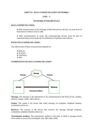
  • 1. 20MCT31 - DATA COMMUNICATION NETWORKS UNIT – 1 NETWORK FUNDAMENTALS DATA COMMUNICATION: ● Data communication is the exchange of data between two devices via some form of transmission medium such as cable. ● Data communication to occur, the communicating devices must be part of communicating system made up of combination of hardware and software. EFFECTIVE COMMUNICATION: The effectiveness of data communication depends on ● Delivery ● Accuracy ● Timeliness ● Jitter COMPONENTS OF DATA COMMUNICATION: Message: The message is the information to be communicated in the form of text, number, pictures, images, audio, video and etc.... Sender: The sender is the device that sends message via computer, telephone handset, workstation and so on.... Receiver: The receiver is the device that receives the message through computer, workstation, telephone handset and so on.... Transmission medium: The transmission medium is the path in which a message travels from sender to receiver by twisted pair wire, fiber-optic cable,
  • 2. coaxial cable and radio waves. Protocol: A protocol is a set of rules that govern data communication. Without protocol two devices may be connected but not communicate. DATA FLOW: Simplex: ● Simplex mode is unidirectional communication where the sender sends the data, but the sender cannot receive the data. ● Usage of one channel for transmission of data and also provides less performance than half duplex and full duplex. Eg: Keyboard and Monitor. Half duplex: ● Half duplex is two-way directional communication but one at a time, that is sender can send the data also receive the data one at a time. ● Usage of one channel for transmission of medium and provides less performance than full duplex. Eg: Walkie-Talkies Full duplex: ● Full duplex is a two-way directional communication, where the sender can send the data and receive the data simultaneously. ● Usage of two channels for transmission of data and provides better performance than simplex and half duplexes: Telephone.
  • 3. NETWORK CRITERIA: A network must meet a certain number of criteria, ● Performance ● Reliability ● Security TYPES OF CONNECTION: ● Point to point connection ● Multipoint connection PHYSICAL TOPOLOGY: The topology of network is a geometric representation of the relationship between all the links and the linking devices. There are 4 basic topologies possible ● Mesh ● Star ● Bus ● Ring MESH TOPOLOGY: It is a point-to-point connection to all devices. For n devices mesh has n(n-1)/2 physical channels. Advantage: ● Each and every connection can carry its own data load. ● It is robust. ● Faults are identified easily. ● It provides security and privacy. Disadvantage: ● Installation and configuration are difficult. ● Cabling costs are more. ● Bulk wiring is required.
  • 4. Eg: Connection of telephone regional offices need to connect to every other regional office. STAR TOPOLOGY: In Star topology all hosts are connected to a central device, known as hub device, using a point-to-point connection. Advantage: ● If a single computer within the network stops working, then the rest of the network will work normally. ● This topology is very reliable. ● Fault detection is simple because the links are identified frequently and easily. Disadvantage: ● It needs high maintenance and resources. ● The cables utilized within the network can damage very easily. ● It mainly depends on the central hub. Eg: High speed LAN often uses star topology. BUS TOPOLOGY: In this topology, all the nodes are connected through a single cable known as ‘Backbone’. If this Backbone cable is damaged the entire network breakdowns. Advantages: ● Require less cabling compared to other topologies. ● Easy to implement for small networks. ● It is easy to expand by simply joining two cables together. ● Very cost-effective.
  • 5. Disadvantage: ● This topology is very slow compared to other ● It is difficult to find the fault that occurs. ● Any fault occurs in the cable whole network become lost. ● The performance of the network decreases as traffic increases. Eg: Traditional Ethernet LAN uses bus topology but now it becomes less popular. RING TOPOLOGY: Ring topology is a type of network topology in which each device is connected to two other devices on either side an RJ-45 cable or coaxial cable. Data is commonly transferred in one direction along the ring, known as a unidirectional ring. The data is forwarded from one device to the next, until it reaches the intended destination. Advantage: ● Peer-to-peer configuration offers the best sharing of their all-linked resources. ● Performance of the speed doesn’t degrade even though we add some nodes ● It is capable to manage large number of nodes with excellent communication Disadvantage: ● If any one computer gets down, then the whole network will be affected. ● More expensive to implement than bus topology. ● Unidirectional communication reduces performance. NETWORK TYPES:  Local Area Network  Wide Area Network
  • 6. PROTOCOL LAYERING: When the communication is simple, we need only simple protocol but when the communication is complex, we need to divide the task between different layers, so we need protocols at each layer is known as protocol layering. TCP/IP PROTOCOL SUITE: TCP/IP stands for Transmission Control Protocol/Internet Protocol and is a suite of communication protocols used to interconnect network devices on the internet. TCP/IP is also used as a communications protocol in a private computer network. TCP/IP specifies how data is exchanged over the internet by providing end-to-end communications that identify how it should be broken into packets, addressed, transmitted, routed and received at the destination. The four layers in the TCP/IP protocol suite are:
  • 7. By using logical connections, it makes us easy to understand the duty of each layer. For the application, Transport and network layer is end to end i.e.., internet and the last two layers (datalink and physical layer) have hop to hop i.e.., router. Data unit created in each layer should not be changed by any router or link layer but in last two layers the packet created by host is changed by routers not by link layer switches. PHYSICAL LAYER: The physical layer is responsible for carrying individual bits in a frame across the link. The physical layer is the lowest level in TCP/IP and the communication between two devices in the physical layer is logical communication because of the hidden layer, the transmission medium under the physical layer. Two devices are connected by transmission medium, and we know that transmission medium doesn’t carry bits. It carries optical or electrical signal. So, the bits received in a frame from the data link layer are transformed and sent through transmission media, but we can think that the logical unit between two physical layers in two devices is a bit. DATA LINK LAYER: The routers are responsible for choosing the best links. However, When the next link to travel is determined by the routers, the data link layer is responsible for taking the datagram and moving it across the link. TCP/IP does not define any specific protocol for datalink layer. It supports all standard and proprietary protocols. Any protocols that can take datagram and carry it through link suffices for network layer. The datalink layer takes a datagram and encapsulates it in a packet called a frame. NETWORK LAYER: The network layer is responsible for creating a connection between the source computer and the destination computer. Also, the network layer is responsible for host-to- host communication and routing packet through possible routes. The network layer on the
  • 8. internet includes the main protocol, Internet Protocol that defines the format of the packet called datagram at the network layer. IP is connectionless in that it provides no flow control, no error control and congestion control services. The network layer also has some auxiliary protocols that help IP in its delivery and routing task. ICMP helps IP to report some problems when routing a packet. TGMP is another protocol that helps IP multitasking. DHCP helps IP to get the network layer address for a host. ARP is a protocol that helps IP to find the link layer of the host or router when its network layer is given. TRANSPORT LAYER: The logical connection at the transport connection is also end to end. It is responsible for providing services to the application layer. There are few transports layer protocols on the Internet for specific tasks, the main protocol is TCP which is connection-oriented protocol that establishes a logical connection between transport layer at two host before transferring data. Another, UDP which is connectionless that transmit user datagram without creating logical connection. APPLICATION LAYER: The logical connection between two application layers is end to end. The two layers exchange messages between each other as though there were a bridge between the two layers. Communication at the application layer is between two processes. Process to Process communication is the duty of the application layer, as the process sends a request to another process and receives a response. The application layer in Internet includes many predefined protocols. HTTP is a vehicle for accessing WWW.SMPT is the main protocol used in electronic mail.FTP is used for transferring files from one host to another. DNS is used by another protocol to find the network layer address of a computer. ENCAPSULATION AND DECAPSULATION: One of the important concepts of protocol layering on the internet is encapsulation/decapsulation.
  • 9. ENCAPSULATION AT THE SOURCE HOST: ● At the application layer the data to be exchanged is referred to as a message. A message normally does not contain any header or trailer. The message is passed to the transport layer. ● The transport layer takes the message as the payload, the load that the transport layer should take care of. It adds the transport layer header to the payload, which contain the identifiers of the source and destination application program that want to communicate also some more information that need for end-to-end delivery of the message such as error control, flow. The result of this layer is called segment in TCP and datagram in UDP. Then the layer passes the packet to the network layer. ● The network layer takes the transport layer packet as data and adds its own header to payload. Also, the header contains the address of the source and destination host and some more information. The result of this layer is called datagram and this passes to datalink layer. ● The datalink layer takes the network layer packet as data and adds its own header which contains the link layer address of host. The result of link layer is called frame, and this is passed to physical layer for transmission. DECAPSULATION AND ENCAPSULATION AT THE ROUTER: At the router we have both encapsulation and decapsulation because the router is connected to two or more links. ● After the set of bits are delivered to the datalink layer this layer decapsulates the datagram from the frame and passes it to the network layer. ● The network layer only inspects the source and destination address in the datagram header and consults its forwarding table to find the next hop to which datagram is to be delivered. The datagram layer is then passed to the data link layer of the next link. ● The datalink layer of the next link encapsulates the datagram in a frame andpasses it to the physical layer for transmission. DECAPSULATION AT THE DESTINATION HOST: At the destination host each layer only decapsulates the packet received, removes the payload and delivers the payload to the next higher layer protocol until the message reaches the application layer. It is necessary to say that decapsulation in the host involves error checking. ADDRESSING: There is logical communication between a pair of layers and any communication that involves two parties needs two address ie., source address and destination address. At application layer we use name to define the site that provides services and at transport layer address are called port numbers.
  • 10. At network layer the address is global and link layer address called MAC addresses each of which defines a specific host or router in a network. MULTIPLEXING AND DEMULTIPLEXING: Multiplexing means that a protocol at a layer can encapsulate a packet from several next higher layer protocols. Demultiplexing means that a protocol can decapsulate and deliver a packet to several next higher layer protocols. Multiplex and demultiplex a protocol needs to have a field in its header to identify to which protocol the encapsulated packet belongs. At transport layer either UDP or TCP can accept a message from several application layers. IP can accept protocols from TCP or UDP and ICMP, IGMP and so on. THE OSI MODEL: The Open Systems Interconnection (OSI) model has seven layers that computer systems use to communicate over a network. Open System Interconnection (OSI Model) also defines a logical network and effectively describes computer packet transfer by using various layers of protocols.
  • 11. 1. Physical Layer: ● The physical layer is responsible for the physical cable or wireless connection between network nodes. ● It defines the connector, the electrical cable or wireless technology connecting the devices, and is responsible for transmission of the raw data, which is simply a series of 0s and 1s, while taking care of bit rate control. 2. Data Link Layer ● The data link layer establishes and terminates a connection between two physically- connected nodes on a network. It breaks up packets into frames and sends them from source to destination. ● This layer is composed of two parts—Logical Link Control (LLC), which identifies network protocols, performs error checking and synchronizes frames, and Media Access Control (MAC) which uses MAC addresses to connect devices and define permissions to transmit and receive data. 3. Network Layer ● The network layer has two main functions. One is breaking up segments into network packets, and reassembling the packets on the receiving end. ● The other is routing packets by discovering the best path across a physical network.
  • 12. ● The network layer uses network addresses (typically Internet Protocol addresses) to route packets to a destination node. 4. Transport Layer ● The transport layer takes data transferred in the session layer and breaks it into “segments” on the transmitting end. ● It is responsible for reassembling the segments on the receiving end, turning it back into data that can be used by the session layer. ● The transport layer carries out flow control, sending data at a rate that matches the connection speed of the receiving device, and error control, checking if data was received incorrectly and if not, requesting it again. 5. Session Layer ● The session layer creates communication channels, called sessions, between devices. ● It is responsible for opening sessions, ensuring they remain open and functional while data is being transferred, and closing them when communication ends. ● The session layer can also set checkpoints during a data transfer—if the session is interrupted, devices can resume data transfer from the last checkpoint. 6. Presentation Layer ● The presentation layer prepares data for the application layer. ● It defines how two devices should encode, encrypt, and compress data so it is received correctly on the other end. ● The presentation layer takes any data transmitted by the application layer and prepares it for transmission over the session layer. 7. Application Layer ● The application layer is used by end-user software such as web browsers and email clients. ● It provides protocols that allow software to send and receive information and present meaningful data to users. ● A few examples of application layer protocols are the Hypertext Transfer Protocol (HTTP), File Transfer Protocol (FTP), Post Office Protocol (POP),Simple Mail Transfer Protocol (SMTP), and Domain Name System (DNS) .
  • 13. OSI VS TCP/IP: ● The TCP/IP is older than the OSI model ● OSI layers 5, 6, 7 are combined into one Application Layer in TCP/IP ● OSI layers 1, 2 are combined into one Network Access Layer in TCP/IP ● TCP/IP is a functional model designed to solve specific communication problems, and which is based on specific, standard protocols. ● OSI is a generic, protocol-independent model intended to describe all forms of network communication. ● In TCP/IP, most applications use all the layers, while in OSI simple applications do not use all seven layers. Only layers 1, 2 and 3 are mandatory to enable any data communication. ANALOG AND DIGITAL DATA: The term analog data refers to information that is continuous. Digital data refers to information that has discrete states.
  • 14. PERIODIC AND NON PERIODIC: A signal is a periodic signal when it is repeated over a cycle of time or regular interval of time. This means periodic signal repeats its pattern over a period. A signal is considered to be non-periodic or aperiodic signal when it does not repeat its pattern over a period. PEAK AMPLITUDE: The peak amplitude of a signal is the absolute value of its highest intensity, proportional to the energy it carries. Peak amplitude is normally measured in volts.
  • 15. PERIOD AND FREQUENCY:  Period refers to the amount of time in seconds, a signal needs to complete 1cycle.  Frequency refers to the number of periods in 1s.  Period and frequency are inversly proportional to each other. F=1/t and T=1/f
  • 16. WAVELENGTH: Wavelength is another characteristic of a signal travelling through a transmission medium. Wavelength binds the period or frequency of a simple sine wave to the propagation speed of the medium. BANDWIDTH: The bandwidth is normally a difference between two numbers ie., Highest frequency and lowest frequency contained in that signal. TRANSMISSION IMPAIRMENT: Signal travel through transmission media which are not perfect. The imperfection causes signal impairment. This means that the signal at the beginning of the medium is not the same as the signal at the end of the medium. Three causes of impairment are ● Attenuation, ● Distortion and ● Noise. ATTENUATION:  Attenuation means a loss of energy. When a signal, Simple or composite, travels through a medium, it loses some of its energy in overcoming the resistance of the medium.  Some of the electrical energy in the signal is converted to heat. To compensate for this loss, amplifiers are used to amplify the signal. DISTORTION:  Distortion means that the signal changes its form or shape. Distortion can occur in a composite signal made of different frequencies.
  • 17.  Each signal component has its own propagation speed through medium and therefore its own delay in arriving at the final destination.  Difference in delay may create a difference in phase if the delay is not exactly the same as the period duration. NOISE:  Noise is another cause of impairment. Several types of noise such as thermal noise, induced noise, crosstalk and impulse noise may corrupt the signal.  Thermal noise is the random motion of electrons in a wire, which creates an extra signal not originally sent by the transmitter.  Induced noise comes from sources such as motors and appliances. These devices act as a sending antenna.  Crosstalk is the effect of one wire on the other. One wire act as the sending antenna and the other as the receiving antenna.  Impulse noise is a spike that comes from power lines, lightning and so on. A high SNR means the signal is less corrupted by noise and a low SNR means the signal is more corrupted by noise.
  • 18. THROUGHPUT AND LATENCY: The throughput is a measure of how fast we can actually send data through network. The latency or delay defines how long it takes for an entire message to completely arrive at the destination from the time the first bit is sent out from the source.
  • 19. UNIT-2 TRANSMISSION MEDIA Transmission media are actually located below the physical layer and are directly controlled by the physical layer. A transmission medium can be broadly defined as anything that can carry information from a source to a destination. Guided media: ● Guided media, which are those that provide a conduit from one device to another, include twisted-pair cable, coaxial cable, and fiber-optic cable. ● A signal traveling along any of these media is directed and contained by the physical limits of the medium. ● Twisted-pair and coaxial cable use metallic (copper) conductors that accept and transport signals in the form of electric current. Optical fiber is a cable that accepts and transports signals in the form of light. 1. Twisted-Pair Cable ● A twisted pair consists of two conductors (normally copper), each with its own plastic insulation, twisted together. ● One of the wires is used to carry signals to the receiver, and the other is used only as a ground reference. Unshielded Versus Shielded Twisted-Pair Cable ● The most common twisted-pair cable used in communications is referred to as unshielded twisted-pair (UTP). ● IBM has also produced a version of twisted-pair cable for its use called shielded twisted-pair (STP). STP cable has a metal foil or braidedmesh covering that encases each pair of insulated conductors. ● Although metal casing improves the quality of cable by preventing the penetration of noise or crosstalk, it is bulkier and more expensive.
  • 20. Connectors The most common UTP connector is RJ45 (RJ stands for registered jack), Applications 1. Twisted-pair cables are used in telephone lines. 2. TP used in telephone network. 3. In LAN, TP wires are mainly used for low cost, low performance applications. 2. Coaxial cable: ● Coaxial cable (or coax) carries signals of higher frequency ranges than those in twisted pair cable. ● It has a central core conductor of solid or stranded wire (usually copper) enclosed in an insulating sheath, which is, in turn, encased in an outer conductor of metal foil, braid, or a combination of the two. ● The outer conductor is also enclosed in an insulating sheath, and the whole cable is protected by a plastic cover. Coaxial Cable Standards ● Coaxial cables are categorized by their radio government (RG) ratings. Each RG number denotes a unique set of physical specifications, including the wire gauge of the inner conductor, the thickness and type of the inner insulator, the construction of the shield, and the size and type of the outer casing. Each cable defined by an RG rating is adapted for a specialized function. Coaxial Cable Connectors ● The most common type of connector used today is the Bayone-Neill-Concelman (BNe), connector. ● Three popular types of these connectors: the BNC connector, the BNC T connector, and the BNC terminator. ● The BNC connector is used to connect the end of the cable to a device, such as a TV set. ● The BNC T connector is used in Ethernet networks to branch out to a connection to a computer or other device. ● The BNC terminator is used at the end of the cable to prevent the reflection of the signal.
  • 21. Applications Coaxial cable was widely used for both analog and digital data transmission. It has higher bandwidth. Inexpensive when compared to fiber optical cables. 3. Fiber-Optic Cable: ● A fiber-optic cable is made of glass or plastic and transmits signals in the form of light. ● Light travels in a straight line as long as it is moving through a single uniform substance. ● If a ray of light traveling through one substance suddenly enters another substance, then the ray changes direction. Figure 1.33 shows how a ray of light changes direction when going from a denser to a less dense substance. ● if the angle of incidence I is less than the critical angle, the ray refracts and moves closer to the surface. ● If the angle of incidence is equal to the critical angle, the light bends along the interface. If the angle is greater than the critical angle, the ray reflects (makes a turn) and travels again in the denser substance. ● Note that the critical angle is a property of the substance, and its value differs from one substance to another. Optical fibers use reflection to guide light through a channel. A glass or plastic core is surrounded by a cladding of less dense glass or plastic. Propagation Modes ● Current technology supports two modes (multimode and single mode) for propagating light along optical channels, each requiring fiber with different physical characteristics.
  • 22.  Multimode can be implemented in two forms: step-index or graded-index. a. Multimode: ● Multimode beams from a light source move through the core in different paths. How these beams move within the cable depends on the structure of the core. In multimode step-index fiber, the density of the core remains constant from the center to the edges. A second type of fiber, called multimode graded-index fiber, decreases this distortion of the signal through the cable. The word index here refers to the index of refraction. b. Single-Mode: ● Single-mode uses step-index fiber and a highly focused source of light that limits beams to a small range of angles, all close to the horizontal. ● The single mode fiber is manufactured with a much smaller diameter. Fiber Sizes Optical fibers are defined by the ratio of the diameter of their core to the diameter of their cladding, both expressed in micrometers.
  • 23. Fiber-Optic Cable Connectors There are three types of connectors for fiber-optic cables. Advantages of Optical Fiber: Fiber-optic cable has several advantages over metallic cable (twisted pair or coaxial). Higher bandwidth. Less signal attenuation. Immunity to electromagnetic interference. Resistance to corrosive materials. Light weight. Greater immunity to tapping. Disadvantages of Optical Fiber: There are some disadvantages in the use of optical fiber. Installation and maintenance. Unidirectional light propagation. Cost. Unguided media: ● Unguided media transport electromagnetic waves without using a physical conductor. ● This type of communication is often referred to as wireless communication. The part of the electromagnetic spectrum, ranging from 3 kHz to 900 THz, used for wireless communication.
  • 24. Wireless transmission into three broad groups: radio waves, microwaves, and infrared waves. 1. Radio Waves: ● Electromagnetic waves ranging in frequencies between 3 kHz and 1 GHz are normally called radio waves; waves ranging in frequencies between 1 and 300 GHz are called microwaves. ● Radio waves, for the most part, are omnidirectional. ● Radio waves are used for multicast communications, such as radio and television, and paging systems. Omnidirectional Antenna Radio waves use omnidirectional antennas that send out signals in all directions. Applications The omnidirectional characteristics of radio waves make them useful for multicasting, in which there is one sender but many receivers. AM and FM radio, television, maritime radio, cordless phones, and paging are examples of multicasting. 2. Microwaves ● Electromagnetic waves having frequencies between I and 300 GHz are called Microwaves. ● Microwaves are unidirectional. When an antenna transmits microwave waves, they can be narrowly focused. ● This means that the sending and receiving antennas need to be aligned. The unidirectional property has an obvious advantage. ● A pair of antennas can be aligned without interfering with another pair of aligned antennas
  • 25. Microwaves are used for unicast communication such as cellular telephones, satellite networks, and wireless LANs. Unidirectional Antenna ● Microwaves need unidirectional antennas that send out signals in one direction. ● Two types of antennas are used for microwave communications: the parabolic dish and the hom. Applications Microwaves, due to their unidirectional properties, are very useful when unicast (communication is needed between the sender and the receiver. They are used in cellular phones, satellite networks and wireless LANs. 3. Infrared: ● Infrared waves, with frequencies from 300 GHz to 400 THz can be used for short-range communication. Infrared waves, having high frequencies, cannot penetrate walls. ● This advantageous characteristic prevents interference between one system and another; a short-range communication system in one room cannot be affected by another system in the next room. Infrared signals can be used for short-range communication in a closed area using line-of-sight propagation. Applications The infrared band, almost 400 THz, has an excellent potential for data transmission. Communication between devices such as keyboards, mice, PCs, and printers. For example, some manufacturers provide a special port called the IrDA port that allows a wireless keyboard to communicate with a PC. SWITCHING: ● A switched network consists of a series of interlinked nodes, called switches. Switches are devices capable of creating temporary connections between two or more devices linked to the switch. ● In a switched network, some of these nodes are connected to the end systems (computers or telephones, for example). Others are used only for routing.
  • 26. CIRCUIT-SWITCHED NETWORKS: ● A circuit-switched network consists of a set of switches connected by physical links. ● A connection between two stations is a dedicated path made of one or more links. Each connection uses only one dedicated channel on each link. Each link is normally divided into n channels by using FDM or TDM. A circuit-switched network is made of a set of switches connected by physical links, in which each link is divided into n channels. ● The end systems, such as computers or telephones, are directly connected to a switch. It shows only two end systems for simplicity. ● When end system A needs to communicate with end system M, system A needs to request a connection to M that must be accepted by all switches as well as by M itself. ● This is called the setup phase; a circuit (channel) is reserved on each link, and the combination of circuits or channels defines the dedicated path. After the dedicated path made of connected circuits (channels) is established, data transfer can take place. After all data have been transferred, the circuits are top down. Three Phases The actual communication in a circuit-switched network requires three phases: connection setup,data transfer,and connection tear down.
  • 27. In circuit switching, there sources need to be reserved during the setup phase;t he resources remain dedicated for the entire duration of data transfer until the tear down phase Setup Phase ● Before the two parties can communicate, a dedicated circuit needs to be established. ● The end systemsarenormallyconnectedthroughdedicatedlinestotheswitches,so connection setup means creating dedicated channels between the switches. ● Note that end-to-end addressing is required for creating a connection between thetwo end systems. These can be,for =example, the addresses of the computers assigned by the administratorina TDM network,or telephone numbers in an FDM network. Data Transfer Phase ● After the establishment of the dedicated circuit (channels),the two parties can transfer data. Teardown Phase ● When one of the parties needs to disconnect, a signal is sent to each switch to release the resources. Efficiency ● It can be argued that circuit-switched networks are not as efficient as the other two types of networks because resources are allocated during the entire duration of the connection. ● These resources are unavailable to other connections. In a telephone network, people normally terminate the communication when they have finished their conversation. ● In computer networks, a computer can be connected to another computer even if there is no activity for a long time. In this case, allowing resources to be dedicated means that other connections are deprived. Delay ● A circuit-switched network normally has low efficiency, so the delay in this type of network is minimal. ● During data transfer the data are not delayed at each switch; there sources are allocated for the duration of the connection. ● The idea ofdelayinacircuit-switchednetworkwhenonlytwoswitchesareinvolved. ● There is no waiting time at each switch. The total delay is due to the time needed to create the connection,transferdata,anddisconnect the circuit. In circuit switching, the resources need to be reserved during the setup phase; the resources remain dedicated for the entire duration of data transfer until the teardown phase.
  • 28. Datagram Networks: ● In data communications, sending messages from one end system to another. ● If the message is going to pass through a packet-switched network, it needs to be divided into packets of fixed or variable size. The size of the packet is determined by the network and the governing protocol. In a packet-switched network, there is no resource reservation; resources are allocated on demand. ● In a datagram network, each packet is treated independently of all others. Even if a packet is part of a multipacket transmission, the network treats it as though it existed alone. Packets in this approach are referred to as datagrams. Datagram switching is normally done at the network layer. It shows how the datagram approach is used to deliver four packets from station A to station X. 1. Routing table: ● In this network, each switch (or packet switch) has a routing table which is based on the destination address. The routing tables are dynamic and are updated periodically. The destination addresses and the corresponding forwarding output ports are recorded in the tables. This is different from the table of a circuit switched network in which each entry is created when the setup phase is completed and deleted when the teardown phse is over. A switch in a datagram network uses a routing table that is based on the destination address. Destination Address ● Every packet in a datagram network carries a header that contains, among other information, the destination address of the packet. ● When the switch receives the packet, this destination address is examined; the routing table is consulted to find the corresponding port through which the packet should be forwarded.
  • 29. The destination address in the header of a packet in a datagram network remains the same during the entire journey of the packet. Efficiency The efficiency of a datagram network is better than that of a circuit-switched network; resources are allocated only when there are packets to be transferred. If a source sends a packet and there's a delay of a few minutes before another packet can be sent, there sources can be real located during these minutes for other packets from other sources. Delay ● There may be greater delay in a datagram network than in a virtual-circuit network. ● There are no setup and teardown phases, each packet may experience a wait at a switch before it is forwarded. ● Here not all packets in a message necessarily travel through the same switches, the delay is not uniform for the packets of a message. Delay in a datagram network Datagram Networks in the Internet: ● The Internet has chosen the datagram approach to switching at the network layer. It uses the universal addresses defined in the network layer to route packets from the source to the destination. Virtual-Circuit Networks: ● A virtual-circuit network is a cross between a circuit-switched network and a datagram network. ● It has some characteristics of both. 1. As in a circuit-switched network, there are setup and teardown phases in addition to the data transfer phase. 2. Resources can be allocated during the setup phase, as in a circuit- switched network, or on demand, as in a datagram network. 3. As in a datagram network, data are packetized and each packet carries an address in the header. However, the address in the header has local jurisdiction not end-to-end jurisdiction. The reader may ask how the intermediate switches know where to send the packet if there is no final destination address carried by a packet.
  • 30. 4. As in a circuit-switched network, all packets follow the same path established during the connection. 5. A virtual-circuit network is normally implemented in the data link layer, while a circuit-Switched network is implemented in the physical layer and a datagram network in the network layer. 1. Addressing In a virtual-circuit network, two types of addressing are involved: global and local (virtual-circuit identifier). Global Addressing ● A source or a destination needs to have a global address-an address that can be unique in the scope of the network or internationally if the network is part of an international network. Virtual-Circuit Identifier ● The identifier that is actually used for data transfer is called the virtual-circuit identifier (VCl). ● A VCl, unlike a global address, is a small number that has only switch scope; it is used by a frame between two switches. When a frame arrives at a switch, it has a VCI; when it leaves, it has a different VCl. Three Phases ● In a circuit-switched network, a source and destination need to go through three phases in a virtual-circuit network :setup, data transfer,and teardown. Data Transfer Phase • Data transfer occurs between these two phases. We first discuss the data transfer phase, which is more straightforward • To transfer a frame from a source to its destination, all switches need to have a table entry for this virtual circuit. The table, in its simplest form, has four columns.
  • 31. · • This means that the switch holds four pieces of information for each virtual circuit that is already set up. Setup Phase ● In the setup phase, the source and destination use their global addresses to help switches make table entries for the connection. A. switch creates an entry for a virtual circuit. For example, suppose sourceA needs to create a virtual circuit to B. Two steps are required: the setup requests and the acknowledgmentSwitch and tables in a virtual-circuitnetwork 2. Circuit-Switched Technology in WANs ● Virtual-circuit networks are used in switched WANs such as Frame Relay and ATM networks. The data link layer of these technologies is well suited to the virtual-circuit technology. ● Switching at the data link layer in a switched WAN is normally implemented by using virtual- circuit techniques. Teardown Phase In the teardown phase, the source and destination inform the switches to delete the corresponding entry Efficiency Resource reservation in a virtual-circuit network can be made during the setup or can be on demand during the data transfer phase. In the first case, the delay for each packet is the same. STRUCTURE OF A SWITCH Structures Of The Switches Used In Each Type Of Network. Structure of Circuit Switches Circuit switching can use either of two technologies: the space-division switch or the time- division switch. Space-Division Switch ● In space-division switching, the paths in the circuit are separated from one another spatially.This technology was originally designed for use in analog networks but is used currently in both analog and digital networks. It has evolved through a long history of many designs. ● Crossbar Switch A crossbar switch connects n inputs to m outputs in a grid, using electronic micro switches(transistors)at each cross point this design is the number of cross points required.To Connect n inputs to m outputs using a crossbar switch requires n x m cross points.For example, to connect1000 inputs 1000 output requires switch with 1,000,000 cross points. A crossbar with this number of crosspoints is impractical. Such a switch is also inefficient because statistics show that,in practice, fewer than 25 percent of the cross points are in use at any given time.There stare idle. Multistage Switch • The Solution to the limitations of the crossbar switch is the multistage switch,which combines cross bars witches in several(normally three)stages. • Ina single crossbar switch,only one row or column(one path) is active for any connection. So we need N x N crosspoints.
  • 32. • If we can allow multiple paths inside the switch,we can decrease the number of crosspoints.Each Crosspoint in the middle stage can be accessed by multiple crosspoints in in the first or third stage. Multistage Switch Time-DivisionSwitch Time-division switching uses time-division multiplexing (TDM) inside a switch. The Most Popular Technology Is Called The Time-slot interchange(TSI). Time-Slot Interchange Figure 8.19 shows a system connecting four input lines to four output lines.Imagine that each input line wants to send data to an output line according the following pattern: Structureof PacketSwitches A switch used in a packet-switched network has a different structure from a switch used in a circuit- switched network.We can say that a packet switch has four components:input ports,output ports,the routing processor,and the switching fabric InputPorts An input port performs the physical and data link functions of the packet switch. Thebits are constructed from the received signal. The packet is decapsulated from the frame.Errors are detected and corrected. The packet is now ready to be routed by the network layer. In addition to a physical layer processor and a data link processor, the input port as buffers (queues) to hold the packet before it is directed to the switching fabric. OutputPort: The output port performs the same functions as the input port, but in the reverse order.First the outgoing packets are queued, then the packet is encapsulated in a frame, andfinally the physical layer functions are applied to the frame to create the signal to besentontheline.Figure8.23showsa schematicdiagramofanoutputport. Routing Processor The routing processor performs the function of the network layer. The destination address is used to find the address of the next hop and, at the same time, the output port number from which the packet is sent out.
  • 33. This activity is sometimes referred to as table lookup because the routing processor searches the routing table. In the newer packet switches,this function of the routing processor is being moved to the input ports to facilitate and expedite the process. Switch Fabrics The most difficult task in a packet switch is to move the packet from input queue to the output queue. The speed with which this is done affects the size of the input/output queue and the overall delay in packet delivery. In the past, when a packet switch was actually a dedicated computer, the memory of the computer or a bus was used as the switching fabric. The input port stored the packet in memory; the output port retrieved the packet from memory. ERROR DETECTION AND CORRECTION BLOCK CODING ● We divide our message into blocks, each of k bits, called datawords. ● We add r redundant bits to each block to make the length n = k + r. ● The resulting n-bit blocks are called codewords Error Detection 1. The receiver has (or can find) a list of valid codewords. 2. The original codeword has changed to an invalid one. Example: Let us assume that k = 2 and n = 3. Table 10.1 shows the list of datawords and codewords. Later, We will see how to derive a codeword from a dataword. Step 1.The receiver receives 011. It is a valid codeword. The receiver extracts the dataword 01 from it. Step 2. The codeword is corrupted during transmission, and 111 is received (the leftmost bit is corrupted). This is not a valid codeword and is discarded.
  • 34. Step 3. The codeword is corrupted during transmission, and 000 is received (the right two bits are corrupted). This is a valid codeword. The receiver incorrectly extracts the dataword 00. Two corrupted bits have made the error undetectable. Hamming Distance ● One of the central concepts in coding for error control is the idea of the Hamming distance. ● The Hamming distance between two words (of the same size) is the number of differences between the corresponding bits. ● The Hamming distance can easily be found if we apply the XOR operation (⊕) on the two words and count the number of 1s in the result. Minimum Hamming Distance for Error Detection:- ● Minimum Hamming distance is the smallest Hamming distance between all possible pairs of codewords. Linear Block Codes: ● Almost all block codes used today belong to a subset of block codes called linear block codes. ● The use of nonlinear block codes for error detection and correction is not as widespread because their structure makes theoretical analysis and implementation difficult. ● We therefore concentrate on linear block codes. Example: Find Minimum Distance for Linear Block Codes The numbers of 1s in the nonzero codewords are 2, 2, and 2. So the minimum Hamming distance is dmin = 2. Parity-Check Code ● Perhaps the most familiar error-detecting code is the parity-check code. ● This code is a linear block code. In this code, a k-bit dataword is changed to an n-bit codeword where n = k + 1. ● The extra bit, called the parity bit, is selected to make the total number of 1s in the codeword even.
  • 35. The code is also a parity-check code with k = 4 and n = 5. Encoder and decoder for simple parity-check code: ● The calculation is done in modular arithmetic. ● The encoder uses a generator that takes a copy of a 4-bit dataword (a0, a1, a2, and a3) and generates a parity bit r0. The dataword bits and the parity bit create the 5-bit codeword. ● The parity bit that is added makes the number of 1s in the codeword even. ● This is normally done by adding the 4 bits of the dataword (modulo-2); the result is the parity bit. r0 =a3 + a2 + a1 + a0 (modulo-2) If the number of 1s is even, the result is 0; if the number of 1s is odd, the result is 1. In both cases, the total number of 1s in the codeword is even. The addition is done over all 5 bits. The result which is called the syndrome, is just 1 bit. s0 = b3 + b2 + b1 + b0 + q0 (modulo-2) “A parity-check code can detect an odd number of errors.” CYCLIC CODES: ● Cyclic codes are special linear block codes with one extra property. ● In a cyclic code, if a codeword is cyclically shifted (rotated), the result is another codeword. Cyclic Redundancy Check ● we simply discuss a subset of cyclic codes called the cyclic redundancy check (CRC), which is used in networks such as LANs and WANs.
  • 36. Example for Cyclic redundancy by send and receiver Dividend:1010111 Divisor:10010 1 Polynomials  A pattern of 0s and 1s can be represented as a polynomial with coefficients of 0 and The power of each term shows the position of the bit; the coefficient shows the value of the bit.Below diagram shows how to translate a binary pattern into a polynomial; in Figure 10.8b we show how the polynomial can be shortened by removing all terms with zero coefficients and replacing x1 by x and x0 by 1.  It shows one immediate benefit; a 7-bit pattern can be replaced by three terms. The benefit is even more conspicuous when we have a polynomial such as x23 + x3 + 1. Here the bit pattern is 24 bits in length (three 1s and twenty-one 0s) while the polynomial is just three terms.
  • 37. A polynomial to represent a binary word Cyclic Code Encoder Using Polynomials The criteria for a good polynomial generator: CHECKSUM: Checksum is an error-detecting technique that can be applied to a message of any length. In the Internet, the checksum technique is mostly used at the network and trans- port layer rather than the data-link layer. The message is first divided into m-bit units. The generator then creates an extra m-bit unit called the checksum, which is sent with the message. A good polynomial generator needs to have the following characteristics: It should have at least two terms. The coefficient of the term x0 should be 1. It should not divide xt 1 1, for tbetween 2 and n 2 1. It should have the factor x 1 1.
  • 38. At the destination, the checker creates a new checksum from the combination of the message and sent checksum. If the new checksum is all 0s, the message is accepted; otherwise, the message is discarded. Note that in the real implementation, the checksum unit is not necessarily added at the end of the message; it can be inserted in the middle of the message. Internet Checksum The Internet has used a 16-bit checksum. The sender and the receiver follow the steps.The sender or the receiver uses five steps. Procedure to calculate the traditional checksum. FORWARD ERROR CORRECTION ● Retransmission of corrupted and lost packets is not useful for real-time multimedia transmission because it creates an unacceptable delay in reproducing. ● It needs to wait until the lost or corrupted packet is resent. We need to correct the error or reproduce the packet immediately. Several schemes have been designed and used in this case that are collectively referred to as forward error correction (FEC) techniques. Using Hamming Distance ● We said that to detect errors, the minimum Hamming distance should be dmin = s + 1. ● It can be shown that to detect t errors, we need to have dmin = 2t + 1. ● If we want to correct 10 bits in a packet, we need to make the minimum hamming distance 21 bits, ● Which means a lot of redundant bits need to be sent with the data.
  • 39. Using XOR In other words, if we apply the exclusive OR operation on N data items (P1 to PN), we can recreate any of the data items by exclusive-ORing all of the items, replacing the one to be created by the result of the previous operation(R). ● This means that we can divide a packet into N chunks, create the exclusive OR of all the chunks and send N + 1 chunks. Chunk Interleaving ● We cannot afford to let all the chunks belonging to the same packet be missing. We can afford to let one chunk be missing in each packet.  That we can divide each packet into 5 chunks.  We can then create data chunk by chunk (horizontally), but combine the chunks into packets vertically.  case, each packet sent carries a chunk from several original packets.
  • 40. Combining Hamming Distance and Interleaving  Hamming distance and interleaving can be combined. We can first create n-bit packets that can correct t-bit errors.  Then we interleave m rows and send the bits column by column.  In this way, we can automatically correct burst errors up to m × t-bit errors. Compounding High- and Low-Resolution Packets Still another solution is to create a duplicate of each packet with a low- resolution redundancy and combine the redundant version with the next packet.we can create four low-resolution packets out of five high-resolution packets and send If packet is lost, we can use the low-resolution version from the next packet. Note that the low-resolution section in the first packet is empty. In this method, if the last packet is lost, it cannot be recovered, but we use the low-resolution version of a packet if the lost packet is not the last one. The audio and video reproduction does not have the same quality, but the lack of quality is not recognized most of the time. Media Access Control (MAC): ● When nodes or stations are connected and use a common link, called a multipoint or broadcastlink.we need a multiple-access protocol to coordinate access to the link. ● All of these protocols belong to a sublayer in the data-link layer called media access control (MAC). Taxonomy of multiple access
  • 41. Random Access: ● In random access or contention methods, no station is superior to another station and none is assigned the control over another. No station permits, or does not permit, another station to send. ● At each instance, a station that has data to send uses a procedure defined by the protocol to make a decision on whether or not to send. This decision depends on the state of the medium . In other words, each station can transmit when it desires on the condition that it follows the predefined procedure, including the testing of the state of the medium. Two features give this method its name. ● First, there is no scheduled time for a station to transmit. Transmission is random among the stations. That is why these methods are called random access. ● Second, no rules specify which station should send next. Stations compete with one another to access the medium. That is why these methods are also called contention methods. 1. ALOHA ● It was designed for a radio (wireless) LAN, but it can be used on any shared medium. ● It is obvious that there are potential collisions in this arrangement. The medium is shared between the stations. When a station sends data, another station may attempt to do so at the same time. The data from the two stations collide and become garbled. Pure ALOHA ● The original ALOHA protocol is called pure ALOHA. This is a simple, but elegant protocol. The idea is that each station sends a frame whenever it has a frame to send. Since there is only one channel to share, there is the possibility of collision between frames from different stations.
  • 42. Frames in a a pure ALOHA Network ● There are four stations (unrealistic assumption) that contend with one another for access to the shared channel. It shows that each station sends two frames; there are a total of eight frames on the shared medium. ● Some of these frames collide because multiple frames are in contention for the shared channel. Frame 1.1 from station 1 and frame 3.2 from station 3. We need to mention that even if one bit of a frame coexists on the channel with one bit from another frame, there is a collision and both will be destroyed. ● The time-out period is equal to the maximum possible round-trip propagation delay, which is twice the amount of time required to send a frame between the two most widely separated stations (2 x Tp)'. ● The back-off time TB is a random value that normally depends on K. The formula for TB depends on the implementation. One common formula is the binary exponential back-off. ● off time TB is a random value that normally depends on K (the number of attempted unsuccessful transmissions). The formula for TB depends on the implementation. One common formula is the binary exponential back-off. Procedure for Pure ALOHA Protocol
  • 43. Vulnerable time: ● Let us find the length of time, the vulnerable time, in which there is a possibility of collision. We assume that the stations send fixed-length frames with each frame taking Tfr S to send. ● Station A sends a frame at time t. Now imagine station B has already sent a frame between t - Tfr and t. This leads to a collision between the frames from station A and station B. ● The end of B's frame collides with the beginning of A's frame. On the other hand, suppose that station C sends a frame between t and t + Tfr. Here, there is a collision between frames from station A and station C. The beginning of C's frame collides with the end of A's frame. ● During which a collision may occur in pure ALOHA, is 2 times the frame transmission time. Pure ALOHA vulnerable time = 2 x Tfr Vulnerable time for pure ALOHA Protocol Slotted ALOHA: ● Pure ALOHA has a vulnerable time of 2 x Tfr . This is so because there is no rule that defines when the station can send. A station may send soon after another station has started or soon before another station has finished. Slotted ALOHA was invented to improve the efficiency of pure ALOHA. ● In slotted ALOHA we divide the time into slots of Tfr s and force the station to send only at the beginning of the time slot.
  • 44. Frames in a slotted ALOHA Network Throughput: ● It can be proved that the average number of successful transmissions for slotted ALOHA is S = G x e-G . The maximum throughput Smax is 0.368, when G = 1. ● Therefore, if a station generates only one frame in this vulnerable time the frame will reach its destination successfully. Vulnerable time for slotted ALOHA protocol 2.Carrier Sense Multiple Access (CSMA) ● To minimize the chance of collision and, therefore, increase the performance, the CSMA method was developed. ● The chance of collision can be reduced if a station senses the medium before trying to use it. Carrier sense multiple access (CSMA) requires that each listen to the medium before sending. Space/time model of the collision in CSMA Vulnerable Time ● The vulnerable time for CSMA is the propagation time Tp. ● This is the time needed for a signal to propagate from one end of the medium to the other. When a station sends a frame, and any other station tries to send a frame during this time, a collision will result.
  • 45. € Persistence Methods: ● Three methods have been devised to answer these questions: the I-persistent method, the nonpersistent method, and the p-persistent method. BehaviorOf Three Persistence Methods Flow diagram for three persistence methods.
  • 46. 3.Carrier Sense Multiple Access with Collision Detection (CSMA/CD): ● The CSMA method does not specify the procedure following a collision. ● Carrier sense multiple access with collision detection (CSMA/CD) augments the algorithm to handle the collision. In this method, a station monitors the medium after it sends a frame to see if the transmission was successful. If so, the station is finished. ● If, however, there is a collision, the frame is sent again. Collision of the first bit in CSMA/CD 4.Carrier Sense Multiple Access with Collision Avoidance (CSMA/CA) ● In a wired network, the received signal has almost the same energy as the sent signal because either the length of the cable is short or there are repeaters that amplify the energy between the sender and the receiver. ● This means that in a collision, the detected energy almost doubles. In wireless network, much of the sent energy is lost in transmission. The received signal has very little energy. ● A collision may add only 5 to 10 percent additional energy. This is not useful for effective collision detection. We need to avoid collisions on wireless networks because they cannot be detected. ● Carrier sense multiple access with collision avoidance (CSMA/CA) was invented for this network. Collisions are avoided through the use of CSMA/CA's three strategies: the interframe space, the contention window, and acknowledgments.
  • 47. Timing in CSMA/CA Interframe Space (IFS): ● Collisions are avoided by deferring transmission even if the channel is found idle. When an idle channel is found, the station does not send immediately. ● It waits for a period of time called the interframe space or IFS. Even though the channel may appear idle when it is sensed, a distant station may have already started transmitting. The distant station's signal has not yet reached this station. Contention Window : ● The contention window is an amount of time divided into slots. A station that is ready to send chooses a random number of slots as its wait time. ● The number of slots in the window changes according to the binary exponential back-off strategy. This means that it is set to one slot the first time and then doubles each time the station cannot detect an idle channel after the IFS time. CSMA/CA and Wireless Networks ● CSMA/CA was mostly intended for use in wireless networks. The procedure described above, however, is not sophisticated enough to handle some particular issues related to wireless networks, such as hidden terminals or exposed terminals. Controlled Access : In controlled access, the stations consult one another to find which station has the right to send. A station cannot send unless it has been authorized by other stations. We discuss three popular controlled-access methods.
  • 48. 1.Reservation ● In the reservation method, a station needs to make a reservation before sending data. Time is divided into intervals. In each interval, a reservation frame precedes the data frames sent in that interval. ● If there are N stations in the system, there are exactly N reservation minislots in the reservation frame. Each minislot belongs to a station. When a station needs to send a data frame, it makes a reservation in its own minislot. The stations that have made reservations can send their data frames after the reservation frame. ● In the first interval, only stations 1, 3, and 4 have made reservations. In the second interval, only station 1 has made a reservation. 2. Polling: ● Polling works with topologies in which one device is designated as a primary station and the other devices are secondary stations. ● All data exchanges must be made through the primary device even when the ultimate destination is a secondary device. ● The primary device controls the link; the secondary devices follow its instructions. It is up to the primary device to determine which device is allowed to use the channel at a given time. The primary device, therefore, is always the initiator of a session. 3.Token Passing: ● In the token-passing method, the stations in a network are organized in a logical ring. In other words, for each station, there is a predecessor and a successor. ● The predecessor is the station which is logically before the station in the ring; the successor is the station which is after the station in the ring. The current station is the one that is accessing the channel now. ● The right to this access has been passed from the predecessor to the current station. The right will be passed to the successor when the current station has no more data to send.
  • 49. CHANNELIZATION PROTOCOLS CHANNELIZATION ● It is a channelization protocol that allows the total usable bandwidth in a shared channel to be shared across multiple stations based on their time, distance and codes. ● It can access all the stations at the same time to send the data frames to the channel. ● Let's consider a transmission line with four users, namely D1, D2, D3, D4. ● Here, when data is transmitted from a destined source for D2, it can also be accessed by D1, D3, D4 because they all are on the same transmission line. ● D1, D3, and D4 can knowingly or unknowingly access the data destined for D2. ● There is a possibility that they thought that data was supposed for them. ● We use Channelization Protocols to solve this problem. ● Channelization is a way to provide multiple access by sharing the available bandwidth in time, frequency, or through code between source and destination nodes. TYPES OF CHANNELIZATION Channelization Protocols can be classified as ● FDMA (Frequency Division Multiple Access) ● TDMA (Time Domain Multiple Access) ● CDMA (Code Division Multiple Access) FREQUENCY DIVISION MULTIPLE ACCESS(FDMA) ● In this technique, the bandwidth is divided into frequency bands, and each frequency band is allocated to a particular station to transmit its data. ● The frequency band distributed to the stations becomes reserved. ● Each station uses a band-pass filter to confine their data transmission into their assigned frequency band. ● Each frequency band has some gap in-between to prevent interference of multiple bands, and these are called guard bands. ADVANTAGES OF FDMA ● FDMA system is easy to implement, and it's not very complex. ● Frequency bands ensure continuous transmission, saving the bits used for synchronization and framing.
  • 50. ● When the traffic is uniform, FDMA becomes very efficient due to its separate frequency band for each station. ● All stations can run simultaneously at all times without waiting for their turn. ● If the channel is not being used, then it sits idle. ● There is no restriction regarding the baseband or modulation. Disadvantages of FDMA ● The bandwidth channel is narrow. ● The planning of the network and spectrum is very time-consuming. ● The presence of a guard band reduces the bandwidth available for use. ● Bandwidth is assigned permanently to each station which reduces its flexibility. TIME DOMAIN MULTIPLE ACCESS (TDMA) ● TDMA is another technique to enable multiple access in a shared medium. ● In this, the stations share the channel's bandwidth time-wise. ● Every station is allocated a fixed time to transmit its signal. ● The data link layer tells its physical layer to use the allotted time. ● TDMA requires synchronization between stations. ● There is a time gap between the time intervals, called guard time, which is assigned for the synchronization between stations. ● The rate of data in TDMA is greater than FDMA but lesser than CDMA. ADVANTAGES OF TDMA ● TDMA separates users according to time, and this ensures that there is no interference from the simultaneous transmissions ● No frequency guard band is required in TDMA ● It shares a single carrier frequency with multiple users. ● It saves power as the user is only active while transmitting in its allotted time frame. ● There is no need for precise, narrow band filters as there is no division in the frequency range. DISADVANTAGES OF TDMA ● If the stations are spread over a wide area, there is a propagation delay, and we use guard time to counter this. ● Slot allocation in TDMA is complex. ● Synchronization between different channels is difficult to achieve. Each station has to know the beginning of its slot and its location. ● The stations configured according to TDMA demand high peak power during uplink in their allotted time slot.
  • 51. CODE DIVISION MULTIPLE ACCESS (CDMA) ● In the CDMA technique, communication happens using codes ● Using this technique, different stations can transmit their signal on the same channel using other codes. ● There is only one channel in CDMA that carries all the signals. ● CDMA is based on the coding technique, where each station is assigned a code (a sequence of numbers called chips). ● It differs from TDMA as all the stations can transmit simultaneously in the channel as there is no time sharing. ● And it differs from FDMA as only one channel occupies the whole bandwidth. ADVANTAGES OF CDMA ● CDMA operates at low power than FDMA and TDMA ● The capacity of a CDMA system is higher than FDMA and TDMA ● CDMA is cost-effective ● It provides high voice quality than TDMA and FDMA. ● It has the most outstanding spectrum efficiency. ● Hackers can't decode the communication on CDMA DISADVANTAGES OF CDMA ● The performance of CDMA decreases with the increasing number of users. ● The cost of CDMA is higher due to the requirement of types of equipment. ● Incorrect code selection can induce delay.
  • 52. UNIT-3 LOGICAL ADDRESSING IP ADDRESSES: Internet address is used to identify the connection of each device to the internet is known as Internet address or IP address. It is the address of the connection that not host or router, because if the device is moved to another network the IP address will be changed. IPV4 ADDRESSES: It is a 32-bit address that uniquely and universally defines the connection of host or router to the internet. In IPV4 the address would not be change even the network changes since it is unique and universe. ADDRESS SPACE: An address space is the total number of address used by the protocol. IPV4 uses 32-bit addresses so that the address space is defined as 232 or 4,294,967,296. CLASSFULL ADDRESSING: IPV4 address were designed with a fixed length prefix, but to consider both small and large networks, The whole address space was divided into five classes A,B,C,D and E. Class A - 8 bits – 0 to 127 Class B – 16 bits – 128 to 191 Class C – 24 bits – 192 to 223 Class D – Not applicable – 224 to 239 Class E – Not applicable – 240 to 255 CLASSLESS ADDRESSING: To solve the address depletion problem, larger address space is required and it is created by increasing the length of IP address though it is implemented in IPV6 in large range.
  • 53. The short term solution is created by using the same address but to change the distribution of the address to provide a fair share between each other is called as classless addressing. Dynamic Host Configuration Protocol (DHCP): Network Address Translation (NAT): A technology that allows a private network to use a setof private addresses for internal communication and a set of global Internet addresses for external communication. PROBLEMS: An ISP is granted a block of addresses starting with 190.100.0.0/16 (65,536 addresses). The ISP needs to distribute these addresses to three groups of customers as follows: a) The first group has 64 customers; each needs 256 addresses. b) The second group has 128 customers; each needs 128 addresses. c) The third group has 128 customers; each needs 64 addresses. Design the subblocks and find out how many addresses are still available after these allocations. Solution: Group 1 Each customer needs 256 addresses. 28 =256 The prefix length is then 32 - 8 =24. The addresses are, 1st Customer: 190.100.0.0/24 190.100.0.255/24 2nd Customer: 190.100.1.0/24190 190.100.1.255/24 ….
  • 54. 64th Customer: 190.100.63.0/24 190.100.63.255/24 Total =64 X 256 =16,384 Group2 For this group, each customer needs 128 addresses. 27 =128 The prefix length is then 32 - 7 =25. The addresses are 1st Customer: 190.100.64.0/25 190.100.64.127/25 2nd Customer: 190.100.64.128/25 190.100.64.255/25 …. 128th Customer: 190.100.127.128/25 190.100.127.255/25 Total =64 X 256 =16,384 3. Group3 For this group, each customer needs 64 addresses. 26 =64 The prefix length is then 32 - 6 =26. The addresses are 1st Customer: 190.100.128.0/26 190.100.128.63/26 2nd Customer: 190.100.128.64/26 190.100.128.127/26 ….. 128th Customer: 190.100.159.192/26 190.100.159.255/26 Total =128 X 64 =8192 Number of granted addresses to the ISP: 65,536 Number of allocated addresses by the ISP: 40,960 Number of available addresses: 24,576 First address: A block of addresses is granted to a small organization. We know that one of the addresses is 205.16.37.39/28. What is the first address in the block? Solution
  • 55. The binary representation of the given address is 11001101 00010000 00100101 00100 I 11. If we set 32 - 28 rightmost bits to 0, we get 11001101 000100000100101 0010000 or 205.16.37.32. Last address: A block of addresses is granted to a small organization. We know that one of the addresses is 205.16.37.39/28. What is the last address? Solution The binary representation of the given address is 11001101 000100000010010100100111. If we set 32 - 28 rightmost bits to 1, we get 11001101 00010000 001001010010 1111 or 205.16.37.47. IPv4 addresses: Change the following IPv4 addresses from binary notation to dotted-decimal notation. a)10000001 00001011 00001011 11101111 b)11000001 10000011 00011011 11111111 Solution We replace each group of 8 bits with its equivalent decimal number and add dots for separation. a)129.11.11.239 b)193.131.27.255 Change the following IPv4 addresses from dotted-decimal notation to binary notation. a)111.56.45.78 b)221.34.7.82 Solution We replace each decimal number with its binary equivalent. a)01101111 00111000 00101101 01001110 b)11011101 00100010 00000111 01010010
  • 56. Classfull addressing: Find the class of each address. a)00000001 00001011 00001011 11101111 b)11000001 10000011 00011011 11111111 c) 14.23.120.8 d)252.5.15.111 Solution a)The first bit is O. This is a class A address. b)The first 2 bits are 1; the third bit is O. This is a class C address. c) The first byte is 14 (between 0 and 127); the class is A. d)The first byte is 252 (between 240 and 255); the class is E. PROCESS TO PROCESS DELIVERY: User Datagram Protocol: The User Datagram Protocol (UDP) is a connection less, unreliable protocol. It provides process – to – process communication instead of host – to – host communication for IP as a service. It is a simple protocol using a minimum of overhead. Example: Sending a small message using UDP takes much less interaction between the sender and receiver than using TCP. User Datagram: User Datagram Protocol (UDP) packets are called as user datagram. It have a fixed – size of 8 bytes made of four fields each of 2 bytes(16 bits). Format of user datagram:
  • 57. UDP services: Process to process communication: UDP uses Socket address to provide process – to – process communication, a combination of IP address and port numbers.  Connectionless Services  Flow Control  Error Control  Checksum  Congestion Control  Encapsulation and Decapsulation  Queuing  Multiplexing and Demultiplexing Transmission Control Protocol: TCP is a connection – oriented, reliable protocol. It defines connection establishment, data transfer and connection tear-down phases to provides a connection – oriented service. It is the most common transport layer protocol in the internet. TCP services: The services offered by TCP in application layer, Process – to – process Communication: It is provided by UDP and TCP using port numbers. Sending and Receiving Buffer: TCP allows the sending process to deliver data as a stream of bytes and allows the receiving process to obtain data as a stream of bytes. It creates an environment in which the two process seem to be connected by an imaginary tube that carries their bytes across internet.
  • 58. Sending and Receiving Buffer: TCP needs buffer for storage. There are two types of buffers, Sending buffer Receiving buffer both are at different direction. Normal buffers are hundreds or thousands of bytes, it depends on the implementation. The sender buffer has three types of chambers, White section is empty where sending process is filled, Colored area holds that have been sent but not yet acknowledged. Shaded area contains bytes to be sent by the sending TCP. Segments: The network layer, as a service provider for TCP, needs to send data in packets, not as a stream of bytes. At the transport layer, TCP groups a number of bytes together into a packet called a segment. The segments are encapsulated in an IP datagram and transmitted. This entire operation is transparent to the receiving process. Full-Duplex Communication: TCP offers full-duplex service, where data can flow in both directions at the same time. Each TCP endpoint then has its own sending and receiving buffer, and segments move in both directions Multiplexing and Demultiplexing: TCP performs multiplexing at the sender and demultiplexing at the receiver However, since TCP is a connection-oriented protocol, a connection needs to be established for each pair of processes Connect-Oriented Service: TCP is a connection-oriented protocol. When a process starts A wants to send to and receive data from another process at site B, the following three phases occur 1. The two TCP's establish a logical connection between them 2. Data are exchanged in both directions 3. The connection is terminated The TCP segment is encapsulated in an IP datagram and can be sent out of order, or lost or corrupted, and then resent. Each may be rated over a different path to reach the destination.
  • 59. Reliable Service: TCP is a reliable transport protocol. It uses an acknowledgment mechanism so check the safe and sound arrival of data. We will discuss this feature further in the section on error control. TCP Features: Numbering System Byte Number Sequence Number Acknowledgment Number Segment: A TCP packets are called as a segment. The packets of TCP has a certain format they are, The Segment consists of header of 20 to 60 bytes by data from the application program. Source port address: This is a 16-bit field that defines the port number of the application program in the host that is sending the segment. Destination port address: This is a 16-bit field that defines the port number of theapplication program in the host that is receiving the segment. Sequence number: This 32-bit field defines the number assigned to the first byte of data contained in this segment. The sequence number tells the destination which byte in this sequence is the first byte in the segment.
  • 60. Acknowledgment number. This 32-bit field defines the byte number that the receiver of the segment is expecting to receive from the other party. If the receiver of the segment has successfully received byte number x from the other party, it returns + I as the acknowledgment number. Acknowledgment and data can be piggybacked together. Header length: This 4-bit field indicates the number of 4-byte words in the TCPheader. The length of the header can be between 20 and 60 bytes. These bits enable flow control, connection establishment and termination, connection abortion, and the mode of datatransfer in TCP. Window size: This field defines the window size of the sending TCP in bytes. Note that the length of this field is 16 bits.This value is normally referred to as the receiving window (rwnd) and is determined by the receiver. The sender must obey the dictation of the receiver in this case. Checksum: This 16-bit field contains the checksum. The inclusion of the checksum forTCP is mandatory. For the TCP pseudoheader, the value for the protocol field is 6. Urgent pointer: This l6-bit field, which is valid, only if the urgent flag is set, is usedwhen the segment contains urgent data. It defines the number that must be added to the sequence number to obtain the number of the last urgent byte in the data section of the segment. Options:There can be up to 40 bytes of optional information in the TCP header. SYN Flooding Attack The connection establishment procedure in TCP is susceptible to a serious security problem called the SYN flooding attack. This happens when a malicious attacker sends a large number of SYN segments to a server, pretending that each of them is corning from a different client by faking the source IP addresses in the datagrams. Piggybacked After connection is established, bidirectional data transfer can take place. The client and server can both send data and acknowledgments in both directions. The acknowledgment is piggybacked with the data. Three-Way Handshaking Most implementations today allow three-way handshaking for connection termination. 1. In a normal situation, the client TCP, after receiving a close command from the client process, sends the first segment, a FIN segment in which the FIN flag is set. Note that a FIN
  • 61. segment can include the last chunk of data sent by the client, or it can be just a control segment. If it is only a control segment, it consumes only one sequence number. 2. The server TCP, after receiving the FIN segment, informs its process of the situation and sends the second segment, a FIN +ACK segment, to confirm the receipt of the FIN segment from the client and at the same time to announce the closing of the connection in the other direction. 3. The client TCP sends the last segment, an ACK segment, to confirm the receipt of the FIN segment from the TCP server. This segment contains the acknowledgment number, which is 1 plus the sequence number received in the FIN segment from the server. This segment cannot carry data and consumes no sequence numbers. Half-Close In TCP, one end can stop sending data while still receiving data. This is called a half- close. Although either end can issue a half-close, it is normally initiated by the client. It can occur when the server needs all the data before processing can begin. The data transfer from the client to the server stops. The server, however, can still send data. When the server has sent all the processed data, it sends a FIN segment, which is acknowledged by an ACK from the client. After half-closing of the connection, data can travel from the server to the client and acknowledgments can travel from the client to the server. CONGESTION CONTROL : Congestion control refers to techniques and mechanisms that can either prevent congestion, before it happens, or remove congestion, after it has happened.
  • 62. 1. Open-Loop Congestion Control In open-loop congestion control, policies are applied to prevent congestion before it happens. In these mechanisms, congestion control is handled by either the source or the destination. a. Retransmission Policy: Retransmission is sometimes unavoidable. If the sender feels that a sent packet is lost or corrupted, the packet needs to be retransmitted. Retransmission in general may increase congestion in the network.Good retransmission policy can prevent congestion. b. Window Policy: Window at the sender side may also affect congestion. The Selective Repeat window is better than the Go-Back-N window for congestion control. This duplication may make the congestion worse. c. Acknowledgment Policy: The acknowledgment policy imposed by the receiver may also affect congestion. If the receiver does not acknowledge every packet it receives, it may slow down the sender and help prevent congestion. A receiver may send an acknowledgment only if it has a packet to be sent or a special timer expires. A receiver may decide to acknowledge only N packets at a time. d. Discarding Policy: A good discarding policy by the routers may prevent congestion and at the same time may not harm the integrity of the transmission. e. Admission Policy: An admission policy is a quality-of-service mechanism, can also prevent congestion in virtual-circuit networks. Switches in a flow, first check the resource requirement of a flow
  • 63. before admitting it to the network. A router can deny establishing a virtual circuit connection if there is congestion in the network or if there is a possibility of future congestion. 2. Closed-Loop Congestion Control Closed-loop congestion control mechanisms try to alleviate congestion after it happens. Several mechanisms have been used by different protocols. a. Backpressure The technique of backpressure refers to a congestion control mechanism in which a congested node stops receiving data from the immediate upstream node or nodes. The backpressure technique can be applied only to virtual circuit networks, in which each node knows the upstream node from which a flow of data is corning. b. Choke Packet A choke packet is a packet sent by a node to the source to inform it of congestion. Note the difference between the backpressure and choke packet methods.In the choke packet method, the warning is from the router, which has encountered congestion, to the source station directly. The intermediate nodes through which the packet has traveled are not warned. c. Implicit Signaling In implicit signaling, there is no communication between the congested node or nodes and the source. The source guesses that there is congestion somewhere in the network from other symptoms.The delay in receiving an acknowledgment is interpreted as congestion in the network; the source should slow down. d. Explicit Signaling The node that experiences congestion can explicitly send a signal to the source or destination. The explicit signaling method, however, is different from the choke packet method. Explicit signaling in Frame Relay congestion control, can occur in either the forward or the backward direction.
  • 64. QUALITY OF SERVICE (QOS): Quality of service is the use of mechanisms or technologies that work on a network to control traffic and ensure the performance of critical applications with limited network capacity. It enables organizations to adjust their overall network traffic by prioritizing specific high-performance applications. Techniques to Improve QoS The four common methods: scheduling, traffic shaping, admission control, and resource reservation. a. Scheduling Packets from different flows arrive at a switch or router for processing. A good scheduling technique treats the different flows in a fair and appropriate manner. Three scheduling techniques of them : FIFO queuing, priority queuing, and weighted fair queuing. i. FIFO Queuing In first-in, first-out (FIFO) queuing, packets wait in a buffer (queue) until the node (router or switch) is ready to process them. If the average arrival rate is higher than the average processing rate, the queue will fill up and new packets will be discarded. ii. Priority Queuing In priority queuing, packets are first assigned to a priority class. Each priority class has its own queue. The packets in the highest-priority queue are processed first. Packets in the lowest- priority queue are processed last. A priority queue can provide better QoS than the FIFO queue because higher priority traffic, such as multimedia, can reach the destination with less delay. There is a potential drawback. If there is a continuous flow in a high-priority queue, the packets in the lower- priority queues will never have a chance to be processed. This is a condition called starvation.
  • 65. iii. Weighted Fair Queuing A better scheduling method is weighted fair queuing. In this technique, the packets are still assigned to different classes and admitted to different queues. The system processes packets in each queue in a round-robin fashion with the number of packets selected from each queue based on the corresponding weight. b. Traffic Shaping or policing Traffic shaping is a mechanism to control the amount and the rate of the traffic sent to the network. Two techniques can shape traffic. i. Leaky Bucket If a bucket has a small hole at the bottom, the water leaks from the bucket at a constant rate as long as there is water in the bucket. The rate at which the water leaks does not depend on the rate at which the water is input to the bucket unless the bucket is empty. The input rate can vary, but the output rate remains constant. Similarly, in networking, a technique called leaky bucket. ii. Token Bucket The leaky bucket is very restrictive. It does not credit an idle host. For example, if a host is not sending for a while, its bucket becomes empty. Now if the host has bursty data, the leaky bucket allows only an average rate. The time when the host was idle is not taken into account. On the other hand, the token bucket algorithm allows idle hosts to accumulate credit for the future in the form of tokens. c. Resource Reservation A flow of data needs resources such as a buffer, bandwidth, CPU time, and so on. The quality of service is improved if these resources are reserved beforehand.QoS model is called as Integrated Services, which depends heavily on resource reservation to improve the quality of service.
  • 66. d. Admission Control Admission control refers to the mechanism used by a router, or a switch, to accept or reject a flow based on predefined parameters called flow specifications. Before a router accepts a flow for processing, it checks the flow specifications to see if its capacity and its previous commitments to other flows can handle the new flow.
  • 67. UNIT 4 – WIRELESS COMMUNICATION Wireless communication transfer the information without any physical connection between two or more points. Two kinds of mobility:  User mobility  Device portability User mobility: User who has a access to the similar telecommunication services at different places. Example: User can have a mobile and he can login to his mail account from any desktop to check or compose emails. Device portability: The communication device moves with or without a user. Example: mobile phone Characteristics of communication devices:  Accuracy  Timeliness  Deliver  Jitter Applications of wireless communication and mobile communications:  Vehicles  Emergencies  Business  Infotainment  Location dependant services Services of location dependant:  Location aware services
  • 68.  Follow on services  Privacy  Information services  Support services Examples of wireless devices:  Mobile phones  Pocket computer  Pager  Laptop Multiplexing: Multiplexing describes how several users can share a medium with minimum or no interference.  Space division multiplexing  Frequency division multiplexing  Time division multiplexing  Code division multiplexing Space division multiplexing: For wireless communication, multiplexing can be carried out in four dimensions:  Space  Time  Frequency  Code The task of multiplexing is to assign the 4 dimensions to each communication channel with a minimum of interference and a maximum of medium utilization.
  • 69. 6 -channels(k1-k6) c -code t -time f –frequency Space is represented via circles indicating the interference range The channels k1 to k3 can be mapped onto the three ‘spaces’ s1 to s3 which clearly separate the channels and prevent the interference ranges from overlapping. The space between the interference ranges is sometimes called guard space. The remaining channels (k4 to k6) three additional spaces would be needed. In SDM, a separate sender for each communication channel with a wide enough distance between senders. Problem - if two or more channels were established within the same space Frequency division multiplexing: Subdivide the frequency dimension into several non-overlapping frequency bands. Senders using a certain frequency band can use this band. Guard spaces are needed to avoid frequency band overlapping (also called adjacent channel interference). K1 is allotted its own frequency band.
  • 70. Used for radio stations within the same region, where each radio station has its own frequency. Does not need complex coordination between sender and receiver. Disadvantages - a separate frequency for each possible communication scenario would be a tremendous waste of frequency resources. Time division multiplexing: More flexible multiplexing A channel k1 is given the whole bandwidth for a certain amount of time, i.e., all senders use the same frequency but at different points in time. Two transmissions overlap in time called co-channel interference. To avoid this type of interference, precise synchronization between different senders is necessary. Can assign more sending time to senders with a heavy load and less to those with a light load. Frequency and time division multiplexing can be combined. Guard spaces are needed both in the time and in the frequency dimension. Short period of time
  • 71. One has to control the sequence of frequencies and the time of changing to another frequency. Two senders will interfere as soon as they select the same frequency at the same time. Code division multiplexing: Commercial communication systems Cheap processing power channels ki use the same frequency at the same time for transmission. Exmple - a party with many participants from different countries around the world who establish communication channels, i.e.,they talk to each other, using the same frequency range at the same time. Built-in security: if the language is unknown, the signals can still be received, but they are useless. Advantages – good protection against interference and tapping Disadvantages - high complexity of the receiver. A receiver has to know the code and must separate the channel with user data from the background noise composed of other signals and environmental noise. To apply CDM, precise power control is required. Spread spectrum:
  • 72. Techniques involve spreading the bandwidth needed to transmit data – which does not make sense at first sight. The main advantage of spreading the bandwidth is the resistance to narrowband interface. diagram i) shows narrowband signal from a sender of user data diagram ii) The sender now spreads the signal and converts the narrowband signal into a broadband signal. The energy needed to send the signal but transmitted over a large frequency range. Without losing data, power level of the spread signal can be much lower than that of the original narrowband signal The power level of the user signal can even be as low as the background noise. Hard to detect the user signal from the background noise. diagram iii) During transmission, narrowband and broadband interference add to the signal. The sum of interference and user signal is received diagram iv) The receiver de-spread the signal, converting the spread user signal into a narrowband signal again, while spreading the narrowband interference and leaving the broadband interference. diagram v) The receiver applies a bandpass filter to cut off frequencies left and right of the narrowband signal. Finally, the receiver can reconstruct the original data because the power level of the user signal is high enough. Spreading the spectrum can be achieved in two ways. They are  Direct Sequence Spread Spectrum(DSSS)
  • 73.  Frequency Hoping Spread Spectrum(FHSS) Direct Sequence Spread Spectrum(DSSS): Systems take a user bit stream and performan (XOR) with a so-called chipping sequence. The chipping sequence consists of smaller pulses called chips. If the chipping sequence is generated properly it appears as random noise: this sequence is also sometimes called pseudo-noise sequence The spreading factor s = tb/tc determines the bandwidth of the resulting signal. Barker codes exhibit a good robustness against interference and insensitivity to multi-path propagation. Other known Barker codes are 11, 110, 1110, 11101, 1110010, and 1111100110101 DSSS Transmitter:
  • 74. DSSS Receiver: The DSSS receiver is more complex than the transmitter. The receiver only has to perform the inverse functions of the two transmitter modulation steps . However, noise and multi-path propagation require additional mechanisms to reconstruct the original data. The first step in the receiver involves demodulating the received signal. This is achieved using the same carrier as the transmitter reversing the modulation and results in a signal with approximately the same bandwidth as the original spread spectrum signal. Additional filtering can be applied to generate this signal. DSSS works perfectly well if transmitter and receiver are perfectly synchronized and the signal is not too distorted by noise or multi-path propagation. Frequency hopping spread spectrum : The total available bandwidth is split into many channels of smaller bandwidth plus guard spaces between the channels. Transmitter and receiver stay on one of these channels for a certain time and then hop to another channel. This system implements FDM and TDM. The pattern of channel usage is called the hopping sequence, the time spend on a channel with a certain frequency is called the dwell time. Two or more transmitters may choose the same frequency for a hop, but dwell time is short for fast hopping systems, so interference is minimal.
  • 75. The receiver of an FHSS system has to know the hopping sequence and must stay synchronized. Compared to DSSS, spreading is simpler using FHSS systems. FHSS systems only use a portion of the total band at any time, while DSSS systems always use the total bandwidth available. DSSS signals are much harder to detect – without knowing the spreading code, detection is virtually impossible. Motivation for a specialized MAC  Hidden and exposed terminals  Near and far terminals Hidden and exposed terminals: Two nodes that are outside each other’s range perform simultaneous transmission to a node that is within a range of each of them, hence there is a packet collision Problem - node within the range of node is transmitting and cannot transmit to any node.
  • 76. Near and far terminals: The near/far effect is a severe problem of wireless networks using CDM. All signals should arrive at the receiver with more or less the same strength. Space Division Multiple Access(SDMA): Used for allocating a separated space to users in wireless networks. SDMA is never used in isolation but always in combination with one or more other schemes. The basis for the SDMA algorithm is formed by cells and sectorized antennas which constitute the infrastructure implementing SDM. Frequency Division Multiple Access: Comprises all algorithms allocating frequencies to transmission channels according to the frequency division multiplexing (FDM) Channels can be assigned to the same frequency at all times, i.e., pure FDMA, or change frequencies according to a certain pattern, i.e., FDMA combined with TDMA. Sender and receiver have to agree on a hopping pattern, otherwise the receiver could not tune to the right frequency. Hopping patterns are typically fixed, at least for a longer period. Assign a certain frequency to a transmission channel between sender and receiver. Time Division Multiple Access(TDMA) Assign the fixed sending frequency to a transmission channel between a sender and a receiver for a certain period of time. Fixed TDM: The simplest algorithm for using TDM is allocating time slots for channels in a fixed pattern. Fixed access patterns (at least fixed for some period in time) fit perfectly well for connections with a fixed bandwidth. Fixed TDM patterns are used to implement multiple access and a duplex channel between a base station and mobile station. Classical Aloha: The simple Aloha works fine for a light load and does not require any complicated access mechanisms. Slotted Aloha: Random, distributed(no arbitrer) , time multiplex.
  • 77. Additionally used time slots, sending must always start at slot boundaries. Carrier sense multiple access: Sensing the carrier before accessing the medium. Sensing the carrier and accessing the medium only if the carrier is idle decreases the probability of a collision. Demand Assign Multiple Access(Reservation Aloha): Channel efficiency only 18% for Aloha and 36% slotted aloha Reservation can increase efficiency to 80%  Sender receives a future time-slot  Sending within the reserved time slot is possible without collision  Reservation also causes higher delays  Typical scheme for satellite links Packet Reservation Multiple Access(PRMA): Implicit reservation Slots can be reserved implicitly. A certain number of slots form a frame. Stations compete for empty slot according to the slotted Aloha principle. Reservation TDMA: Every frame consists of N mini-slots and X data-slots. Every station has its own mini-slot and can reserve up to k-data slots using this mini- slots. Other station can send data in unused data-slots according to round-robin sending scheme. Multiple Access with Collision Avoidance(MACA): Uses short signaling packets for collision avoidance. RTS(request to send): a sender request the right to send from a receiver with a short RTS packet before it sends a data packet.
  • 78. CTS(clear to send): the receiver grants the right to send as soon as it is ready to receive. Signaling packets contain  Sender address  Receiver address  Packet size Polling: Strictly centralized scheme Where one station is to be heard by all others polling schemes (known from the mainframe/terminal world) can be applied. One master and several slave stations Round robin Inhibit Sense Multiple Access : Combination of different schemes used for the packet data transmission service Cellular Digital Packet Data (CDPD) in the AMPS mobile phone system, is also known as digital sense multiple access (DSMA) Code Division Multiple Access(CDMA): codes to separate different users in code space and to enable access to a shared medium without interference. The main problem is how to find “good” codes and how to separate the signal from noise generated by other signals and the environment. Each sender has a unique random number, the sender XORs the signal with this random number. The receiver can “tune” can turn into this signal , if it knows the pseudo random number, tuning its done via a correlation function. Advantages – All terminals can use the same frequency, no planning needed Huge code space compared to frequency space Interferences is not coded
  • 79. Disadvantages – Higher complexity of a receiver All signals should have the same strength at a receiver