
Recommended
More Related Content
Similar to Design of stairs
Similar to Design of stairs (20)
More from Bahzad5
More from Bahzad5 (20)
Recently uploaded
Recently uploaded (20)
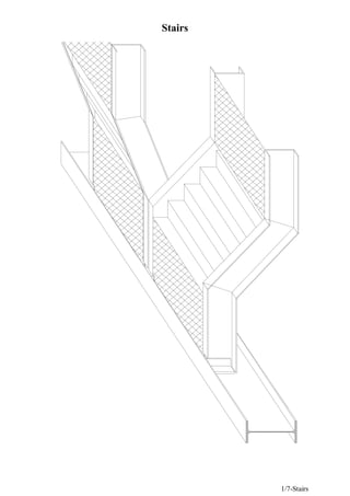
Design of stairs
- 2. Stairs 2/7-Stairs Design of step: Steps are made of checkered plate 6/8 as shown Assume o.w. of step = 20 kg / m L.L = 300 → 500 kg / m2 F.C. may be used W = 1000 20 + (F.C. + L.L.) b Calculate M = 8 2 wa Q = 2 wa Fbcx = 1.4 t/cm2 (lip is small, so neglect L.T.B.) Check f, q, a L L = → ≤ 300 δ Width of stairs is about 1→1.5 m Slope is 1:2 in most cases. Design of stair beam: (Usually used as channel) 26.5 θ ≈ assume o.w. = 25 kg/m weight of step, handrail, (all steel structure) ws = 70 kg/m2 /hz proj L.L = 300 → 500 kg / m2 F.C. = …….. if any W = 1000 25 + (70 + F.C. + L.L.) (a/2) Draw M, Q, (neglect normal) M = 8 2 wL Q = 2 wL Lu act = zero b = 30 cm Checkered plate 5-7 a (6.00) a (4.50) (3.00) a a Beam at 1/2 floor level R 1 M 2 M w = ...... t/m' 1 2
- 3. Stairs 3/7-Stairs Fbcx = 1.4 t/cm2 dmin of channel → Check f, q, δ Design of connection using butt weld: h hw= h = weld h 2 cos channel C 1 3 ° 2 Calculate Ix Check y I M x = …..< 0.7 ft (allowable of good butt weld subjected to tension due to moment or due to tension). Look ECP page Design of beam at 1/2 floor height: (Usually IPE) R = Reaction of stair beam Calculate M, Q If channel is flushed & checkered plate is welded, so Lu act = zero If we use grating Lu act = a Design of connection between channel & I beam: Force = Rt → Rss, Rb as before 3 2 1 0 L70*7 26.5 4 2 h-2t a a R RR R
- 4. Stairs 4/7-Stairs Solved example: It is required a complete design of stairs (steps, beam of stairs with its connection & beam at 1/2 floor height) Given that: L.L. = 400 kg/m2 , F.C. =150 kg/m2 Solution: Design of step: Assume o.w. of step = 20 kg/m Take shape of step as Z – section (assume b = 30cm) (checkered plate 6/8) WDL = 20 + 150 * 0.3 = 65 kg/m WLL = 400 * 0.3 = 120 kg/m WT = 120 + 65 = 185 kg/m M = 0.185 * 8 25 . 1 2 = 0.036 mt = 3.6 cmt Q = 0.185 * (1.25/2) = 0.11 t Ix = 12 6 . 0 * 30 3 (neglected) + 2 + 2 3 5 . 2 * 4 . 4 * 6 . 0 12 4 . 4 * 6 . 0 = 41.52 cm4 Checks: 1. f = 52 . 41 7 . 4 * 6 . 3 = 0.41 t/cm2 < 1.4 t/cm2 (Lip is small, so we can neglect L.T.B) 2. q = 6 . 0 * 5 * 2 11 . 0 = 0.02 t/cm2 <<< 0.84 t/cm2 3. . .L L δ = 3 4 10 * 52 . 41 * 2100 25 . 1 * 120 * 384 5 = 0.04 cm < = 300 125 0.42 cm 0.5 1.25 (6.00) 1.25 (4.50) (3.00) 3.0 1.25 1.25 c d b a Beam B 1.0 1.0 Lip = 5cm 4.4 t = 0.6 30
- 5. Stairs 5/7-Stairs Design of stair beam: Assume o.w. = 25 kg/m Weight of other steel structure is 70 kg/m WDL = 25 + (70 + 150) * (1.25 / 2) = 162.5 kg/m WLL = 400 * (1.25 / 2) = 250 kg/m Wtotal = 250 + 162.5 = 412.5 kg/m M = 8 5 . 5 * 41 . 0 2 = 1.56 mt Q = 0.41 * (5.5 / 2) = 1.13 t Assume Fbcx = 1.4 t/cm2 Sx = 156 / 1.4 = 111 cm3 Choose channel 160 Checks: Lu act = zero So No L.T.B. f t c = 05 . 1 05 . 1 75 . 0 5 . 6 − − = 4.48 < 10.9 w w t d = 11.6 / 0.75 = 15.5 < 82 Therefore, the section is not slender (simply symmetric channel) 1. f = 156 / 116 = 1.34 t/cm2 < 1.4 t/cm2 2. q = 75 . 0 * 16 13 . 1 = 0.09 t/cm2 < 0.84 t/cm2 3. 6 4 . . 10 * 925 * 2100 5 . 5 * 25 . 0 * 384 5 = L L δ = 1.53 cm < 550/300 = 1.83cm 1.13 w = 0.41 t/m' 1.56 1.41
- 6. Stairs 6/7-Stairs Min channel: 94 . 9 2 2 = − t h (From drawing) cm t 1 ≈ h = 22 cm Choose channel minimum 220 Design of connection butt weld: M connection = 1.13 * 1.25 = 1.41 mt ο 25 . 13 2 = θ hweld = 25 . 13 cos 22 = 22.6 cm Ix = 2 3 ) 2 25 . 1 2 6 . 22 ( * ) 9 . 0 8 ( * 25 . 1 * 2 12 6 . 22 * 9 . 0 − − + = 2888.4 cm4 f = 55 . 0 2 6 . 22 * 4 . 2888 141 = t/cm2 < 0.7*1.4 = 0.98 t/cm2 Design of connection between channel & beam at 1/2 floor beam: R = 1.13 t (use only one angle) Rss = 4 * 25 . 0 * 6 . 1 * 4 2 π = 2.01t tmin is smaller of 0.7 or 0.9 (tw of channel) Rb = (0.8 * 3.6)*1.6*0.7 = 3.22 t n = 1.13 / 2.01 = 0.56 use 2 bolts min plate Chequerd L70*7 =9.94 2 h-2t 30cm 5cm L70*7 26.5 0 t=0.9 22.6 t=1.25 8
- 7. Stairs 7/7-Stairs Design of beam B (at mid floor level) Rtotal stair beam = 1.13 t, O.W. = 50 kg/m' RLL stair beam = 0.25 * 5.5 / 2 = 0.69 t (To be used in check of deflection) Mconc = 2.385 x 2.25 – 1.13 x 1.25 – 0.05 x 1.252 /2= 3.83 mt Q = 0.03 x 5 / 2 + 1.13 x 4 / 2 = 2.385 mt Assume Fbcx = 0.64 Fy = 1.54 t/cm2 Sx = 383/ 1.54 = 259 cm3 choose IPE 220 Checks: f t c = 92 . 0 2 . 1 * 2 59 . 0 11 − − = 8.7 < 10.9 , w w t d = 21.2 / 0.59 =35.9 < 82 Assume using checkered plate welded to upper flange of beam So Lu act = zero Fbcx = 0.64 Fy 1. f = 383 / 252 = 1.52 t/cm2 < 1.54 t/cm2 2. q = 2.38 22*0.59 = 0.18 t/cm2 < 0.84 t/cm2 3.51 0.69 1.725 0.54 0.56 0.69 0.69 0.69 1.25 1.25 3. deflection due to live load only " RLL stair beam " ε M = 3.51 * 2.5 – 0.56 * (0.25/2) – 0.54 * (0.5 + 1.25/3) – 1.725 * (0.25 + 1.25/2) – 0.69 * (0.25 + 1.25 + 1/3) = 5.43 m3 t 2770 * 2100 10 * 43 . 5 6 . . = L L δ = 0.93 cm < 550/300 = 1.67cm 1.25 1.25 1.13 1.13 1.13 1.00 1.00 0.5 0.05