GSM System Call Setup
•
11 likes•2,424 views

Unit 5 : wireless communication : GSM System operations

Recommended
More Related Content
What's hot
What's hot (20)
Viewers also liked
Viewers also liked (17)
Similar to GSM System Call Setup
Similar to GSM System Call Setup (20)
More from Ashutha K
More from Ashutha K (7)
Recently uploaded
Recently uploaded (20)
GSM System Call Setup
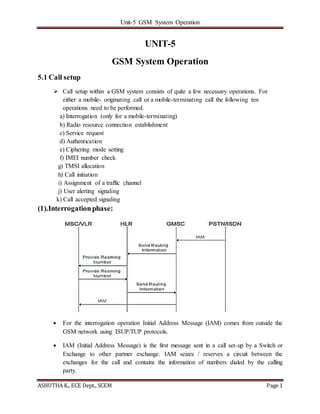
- 1. Unit-5 GSM System Operation ASHUTHA K., ECE Dept., SCEM Page 1 UNIT-5 GSM System Operation 5.1 Call setup Call setup within a GSM system consists of quite a few necessary operations. For either a mobile- originating call or a mobile-terminating call the following ten operations need to be performed. a) Interrogation (only for a mobile-terminating) b) Radio resource connection establishment c) Service request d) Authentication e) Ciphering mode setting f) IMEI number check g) TMSI allocation h) Call initiation i) Assignment of a traffic channel j) User alerting signaling k) Call accepted signaling (1).Interrogationphase: For the interrogation operation Initial Address Message (IAM) comes from outside the GSM network using ISUP/TUP protocols. IAM (Initial Address Message) is the first message sent in a call set-up by a Switch or Exchange to other partner exchange. IAM seizes / reserves a circuit between the exchanges for the call and contains the information of numbers dialed by the calling party.
- 2. Unit-5 GSM System Operation ASHUTHA K., ECE Dept., SCEM Page 2 Other important information contained in an IAM message includes o Originating Point Code OPC o Destination Point Code DPC o Circuit Identification Code CIC o Calling party number o Transmission medium requirement (echo suppresser status etc). GMSC can send a request to the flexible numbering register (FNR) system node before being sent to the HLR. for security reasons, the subscriber data can be simultaneously stored and updated in two HLRs. This built-in system redundancy assures successful operation in all but the most catastrophic disasters. Two GSM system nodes (the MSC/VLR and the GMISC) use a non- MAP protocol to communicate with each other (i.e., the IAM message) (2).Radio resourceconnectionestablishment: Step#1: The MSC/VLR initiates the call setup process by sending paging message to the appropriate BSC. The paging message will contain the subscriber's IMSI number so that the BSC can calculate correct paging group to use. MS can be paged in all the cells of a particular LA or globally in all the cells of a MSC/VLR serving area. LAI is provided by the MSC to the BSC. The BSC receives the paging message and typically translates the LAI to a cell global identity (CGI) number if this information was not provided in the paging message. Step#2: The BSC sends the paging command message to the appropriate BTSs. This message will contain the following information: the IMSI or TMSI, the paging group, and the channel number. The channel number will contain enough information to indicate the channel type and the timeslot number. For this case, the channel type is a downlink common control channel
- 3. Unit-5 GSM System Operation ASHUTHA K., ECE Dept., SCEM Page 3 (CCCH) (i.e.. a paging channel [PCH]). For the GSM system, the paging group is determined by the subscriber's IMSI and other information defined in the BSC. When the MS has received the system information and knows its paging group, it will calculate when this paging group will be broadcast and thereafter will only listen for pages during the time they are expected to be sent. Step#3: BTS sends a paging request message to the MS. This message is sent on the PCH. There are several different types of paging requests possible depending upon the use of IMSI or TMSI numbers If TMSI numbers are used instead of IMSI numbers, up to four MSs may be paged in one paging message. Step#4: The MS responds to the paging request message by sending a channel request message to the BTS. This message is transmitted on RACH and contains information about the type request (i.e.. answer to page, originating call, location updating, emergency call, or other operations) Step#5: BTS sends a channel required message to the BSC. The BSC examines the information contained within the channel required message and determines whether the MS is within the allowed range of the cell. Step#6: The BSC determines what channel to use and sends a channel activation message to the BTS that contains the following: MS and BS power, timing advance (TA), DTX status. Step#7&8: The BTS activates this channel and then sends a channel activation acknowledge message back to the BSC . Step#9: The BSC then sends an immediate assignment command message back to the BTS that includes an immediate assign message for the MS. Step#10:
- 4. Unit-5 GSM System Operation ASHUTHA K., ECE Dept., SCEM Page 4 This immediate assign message is sent by the BTS to the MS over AGCH and instructs the MS to switch to the allocated signaling channel (3).Service request: A layer 2 message known as set asynchronous balanced mode (SABM) which contains the paging response message, is sent from the MS to the BTS. BTS sends back to the MS a layer 2 message in an unnumbered acknowledgement (UA) frame that contains the original paging response message. When the aging response message arrives at the BTS it is forwarded to the BSC in an establish indication message which causes the BSC to activate radio
- 5. Unit-5 GSM System Operation ASHUTHA K., ECE Dept., SCEM Page 5 connection quality supervision and initiates power control algorithms. BSC sends it on to the MSC as a connection request message after it adds the CGI number to the layer 3 information message. Finally, the MSC sends a connection confirm message back to the BSC. (4).Authentication: Depending upon the exchange properties stored in the MSC/VLR, as setup by the GSM operator authentication is either activated or non- activated. If authentication is activated, an authentication request message is sent to the MS. The message containing a 128-bit random number (RAND) and the ciphering key sequence number (CKSN) is sent to the MS. The MS stores the CKSN and then calculates the value of a signed response (SRES) by using the RAND. The values of SRES is returned to the MS/VLR as a transparent authentication response message. A timer is set in the MSC/VLR when the first authentication request message is sent. If the timer expires, the request is sent again. If the timer expires second time, the radio sources are released. (5) Ciphering mode setting MSC/VLR sends the ciphering command to the BSC. This is a BSSMAP message that contains the value of Kc. Kc value is forwarded to the BTS within the encryption command message. BTS stores Kc and send a non-ciphered ciphering mode command message to the MS MS insert Kc and TDMA frame number in to another authentication algorithm(A5) This creates a ciphering sequence that is added to the message that is to be sent. And it is sent BTS and to BSC to MSC. The ciphering key sequence number (CKSN) is used by the GSM system to reduce the
- 6. Unit-5 GSM System Operation ASHUTHA K., ECE Dept., SCEM Page 6 number of steps required for call setup. CKSN stored in SIM card. If MS send CKSN to MSC for call setup without authentication (6).IMEInumber checks: It is an exchange property between MS to MSC/VLR. MSC/VLR sends an identity request message to the MS shown in fig. The MS sends its IMEI to MSC and it checked against the EIR database. EIR can return three statuses. The MS can be: white listed– allowed to use in the network Black listed--- not allowed in the network grey listed--- it is then up to the network operator to decide if the MS can use the network or not (7).TMSIallocation The value of the TMSI number to be used for a particular traffic cases or if one will be used at all is determined by the MSC/VLR software program. MSC/VLR send TMSI to MS via TMSI reallocation command TMSI stored in SIM card and reallocation complete message sent to from MS to
- 7. Unit-5 GSM System Operation ASHUTHA K., ECE Dept., SCEM Page 7 MSC/VLR over an uplink SDCCH. (8).Callinitiation: Call setup process is the transmission of the setup message transparently from the MSC to the MS. CM message is sent over the downlink SDCCH from BTS to MS. This message contains a request for GSM bearer services (voice, fax, etc) The MS will send a call confirmed message on the uplink SDCCH if it can handle the request service. This message is also sent transparently from MS to MSC. A timer is started in the MSC/VLR once the setup message is sent. If the timer expires before the call confirm message is received The connections to the calling subscriber and the mobile subscriber are released. (9).Assignmentof a Traffic channel: It is initiated by the MSC. Shown in Figure, the MSC sends an assignment request message to the BSC. This message contains information about the status of DTX on the downlink, a circuit identity code (CIC) to indicate the transmission path for the speech or data traffic between the MSC and the BSC, and possibly a particular radio channel to facilitate some type of operations and maintenance function.
- 8. Unit-5 GSM System Operation ASHUTHA K., ECE Dept., SCEM Page 8 The BSC could at this time assign the MS to the serving cell, another cell in the BSC serving area, or an external cell depending upon the status of the system and the available radio resources at the time. The BSC must obtain the timing advance information, calculate the MS output power level, select an idle traffic channel, and send a channel activation message to the BTS. The message like full-rate TCH + SACCH + FACCH. The BTS sends an acknowledgement back via a channel activation acknowledgment message to the BSC. The BSC sets up a path through its group switch for the traffic. The BSC sends an assignment command message to the MS that contains the information about the new channel assignment (i.e., TCH + SACCH + FACCH). This radio resource message is sent over the SDCCH. It consists of a complete channel description MS tunes to the new channel and sends a SABM message over the FACCH to indicate successful seizure of the channel. As the BTS receives this message it sends to BSC. The MS then sends an assignment complete message to the MSC to indicate that the traffic channel is working Finally, the BSC sends a message to the BTS that the signaling channel is no longer needed in the form of a RF channel release message. The BTS sends an RF channel release acknowledgement message back to the BSC
- 9. Unit-5 GSM System Operation ASHUTHA K., ECE Dept., SCEM Page 9 (10). Call Confirmation, CallAcceptedand CallRelease: The call confirmation procedure starts when the MS sends a alerting message to the MSC. This message indicates that a ringing tone has been generated in the mobile and that it can be used for user-to-user signaling. When the alerting message is received the MSC/VLR sends the TUP address complete message to the calling subscriber who can now hear the ringing tone generated in the MSC. When the MS user answers, the connect message is sent to the MSC. This message, when received by the MSC, prompts a connect acknowledgement message to be sent back transparently to the MS. These are all connection management messages. The system messages that occur at the end of a call .MSC initiate the call release operation. 5.2 LocationUpdating The operation used to support the subscriber’s mobility within the GSM network is known as location updating. The four different types of location updating used in GSM are: 1. Normal Location Update (Idle Mode)
- 10. Unit-5 GSM System Operation ASHUTHA K., ECE Dept., SCEM Page 10 2. IMSI Detach Location Updating 3. IMSI Attach Location Updating 4. Periodic Location Updating 1. Normal Location Update (Idle Mode) The basic steps involved with location updating look very similar to those used for call setup. The steps are radio resource connection establishment service request, authentication (except for the case of periodic registration), cipher mode setting (dependent upon the circumstances), location updating and then radio resource connection release. Location area is defined as a group of cells that is controlled by one or more BSC’s but only one MSC. When an MS is in idle mode, it listens to system information sent over the BCCH. This information includes the location area identity (LAI) of the servicing cell. If the MS detects an LAI different form that stored in the SIM card the MS must perform a normal location update. The first step of the process is to perform a radio resource connection establishment operation. As shown by figure 1 the MS sends a channel request message over the RACH. The BTS, in turn, sends a channel required message to the BSC. If a free SDCCH is available, the BSC sends a channel activation message to the BSC. Once the channel has been activated, the BSC sends an immediate assignment message to the MS and starts a system timer. When the MS receives the immediate assignment message, it switches to the ordered channel and send a service request via an SABM message that contains a location updating request message to the BTS (figure 2). The message is looped back to the MS via a UA message for reasons mentioned previously and also forwarded to the BSC within an established indication message. When this message arrives at the BSC the timer is disabled and the message is forwarded to the MSC within a connection request message.
- 11. Unit-5 GSM System Operation ASHUTHA K., ECE Dept., SCEM Page 11 The location updating request message will include the old MS location and the new cell location (via the CGI number). The MS acknowledges this layer 3 information by sending a connection confirmed message back to BSC. Authentication and ciphering mode settings operations are similar to those performed during call setup. Figure 1: GSM location updating Radio Resource management Figure 2: GSM location updating Service request
- 12. Unit-5 GSM System Operation ASHUTHA K., ECE Dept., SCEM Page 12 Figure 3: GSM location updating accepted Figure 4: GSM connection release The next step is as shown in fig. 3. If the MSC/VLR accepts the location updating, the MSC/VLR sends the location updating accepted message transparently through the BSC and BTS to the MS over SDCCH. Location updating accepted Data Request (location Updating Accepted) Location updating Accepted TMSI Reallocation Completed Data Indication (TMSI Reallocation Accepted) TMSI Reallocation complete Time
- 13. Unit-5 GSM System Operation ASHUTHA K., ECE Dept., SCEM Page 13 The message sent by the MSC/VLR may contain new TMSI number. If this is the case, the MS responses by sending TMSI reallocation complete message transparently back to the MSC/VLR. When a new TMSI is sent to MS a timer is enabled in MSC. When the MS sends its acknowledgement of the new TMSI back to MSC the timer is disabled when the MSC receives the message. If the location updating request is rejected for whatever reason (IMSI unknown in HLR, “blacklisted “ MS etc.), the MSC sends a location updating reject message to the MS the radio resource connection is released and the MS may be put in an idle state with only emergency call functionality. The last step in the location updating process occurs when the radio resource connection is released. This process is identical to the call release operation discussed in UNIT 2. 2. IMSI Detach Location Updating Figure 5: GSM IMSI Detach The MS uses the IMSI detach procedure when powering off. This process is shown in figure 5. When the MS power is been turned off, the mobile request an SDCCH. Over the SDCCH, the MS sends a message to the network that it is about to enter the detached state. The MSC denotes the MS status (IMSI detached ) in the VLR .The VLR will reject incoming calls for the MS sending a voice message back to the caller that the subscriber is currently unavailable. Alternately the VLR can send a message to HLR indicating the detached condition of the subscriber. If the subscriber has voice mail, the caller will be directed to leave a message for the subscriber. 3. IMSI Attach Location Updating
- 14. Unit-5 GSM System Operation ASHUTHA K., ECE Dept., SCEM Page 14 Figure 6: GSM IMSI Attach The IMSI attach procedure is complementary operation to IMSI detach. If the MS is powered on in the same location area where it is performed an IMSI detach as shown in figure 6. The MS requests a SDCCH, the system receives the IMSI attached message from the MS, the MSC passes the attach message onto the VLR. The VLR returns the MS to active status and resumes normal hand calling for the MS. The MSC/VLR returns an IMSI attack acknowledgement message to the MS. If the IMSI detach process cause the HLR to be updated with the MS’s detached status, the normal location updating will have to be performed by the mobile. If the mobile has changed location area while in detached mode, it will also have to perform a normal location updating when it is switched on again. The signaling used to perform an IMSI attach is basically identical to that of normal location updating. 4. Periodic Location Updating Periodic location updating is used to prevent unnecessary use of network resources such as the paging of detached MS. The system uses periodic registration, the mobile is informed how often it must register. Timers in both the MS and MSC control this operation. When the MS timer expires, the MS performs a location updating that does not require all of the steps involving authentication and ciphering mode setting operations. If the timer in the MSC expires before the MS performs a location updating the MSC denotes the MS as detached. If the updating operation is on time, the MSC sends an acknowledgement to the MS. Any time the MS is activated within the system the periodic updating timers are reset. 5.3 Call Handoff The most common Call handover operations are Intra-BSC handover During an ongoing call, the MS makes measurements of the received signal strength (RSS) of its
- 15. Unit-5 GSM System Operation ASHUTHA K., ECE Dept., SCEM Page 15 own traffic channel (TCH) and the RSS of the neighboring cells. Step #1: MS sends a measurement report about the RSS levels to the BTS at a rate of about two times per second. The BTS also makes measurements of the TCH uplink signal strength and adds these to the measurement report from the MS. Step #2: the combined report is forwarded to the BSC. The BSC uses a locating function to determine the necessity of handing over the call to another cell because of either poor quality or low signal strength in the cell that the MS is attached to. Fig 5.3 Intra BSC handover Step #3: if handover is deemed necessary, the BSC sends a command to the BTS in the new cell to activate a TCH. Step #4: when the new BTS acknowledges the activation of the new TCH, the BSC sends a message to the MS via the old BTS with information about the new TCH (i.e., frequency, timeslot, and mobile output power). Step #5: the mobile tunes to the new TCH and sends short handover access bursts on the appropriate FACCH. At this time, the MS does not use any timing advance. Step #6: when the BTS detects the handover access bursts, it sends timing advance information to the MS over the FACCH. The BTS also sends a handover detection message to the BSC. The BSC reconfigures the group switch to deliver the traffic to the new BTS. Step #7: the MS sends a handover complete message to the BSC. Step #8: the BSC sends a message to the old BTS to deactivate the old TCH and its associated
- 16. Unit-5 GSM System Operation ASHUTHA K., ECE Dept., SCEM Page 16 signaling channel (SACCH). Inter-BSC handover In the inter-BSC handover the mobile has moved to a cell that is in a different location area and therefore has a different BSC. Figure shows this situation. Again, the serving BSC decides that the call must be handed over to a new cell that belongs to a new BSC. Step #1, the serving BSC sends a handover required message to the MSC with the identity of the new cell. Step #2, the MSC determines the serving BSC for the new cell and sends a handover request to the new BSC. Step #3, the new BSC sends an order to the new BTS to activate a TCH. Step #4, when the new BTS activates the TCH, the BSC sends channel information (i.e., frequency, timeslot, MS output power) and a handover reference to the MSC. Step #5, the MSC passes the channel information to the old BSC. Step #6, the MS is instructed to change to the new TCH and it also gets the handover reference information contained in a handover command message. Step #7, the MS tunes to the new TCH and sends handover access bursts containing the handover reference on the new FACCH. Step #8, the new BTS detects the handover access bursts and sends timing advance information to the MS on the FACCH. Step #9 the new BTS sends the handover detection message to the new BSC. The new BSC sends a message to the MSC informing it of a handover. Step #10: when the MS receives the timing advance information it sends a handover complete message to the BSC Step #11: The new BSC sends the handover complete message to old BSC via the MSC. Step #12: The old TCH and SACCH are deactivated by the old BTS.
- 17. Unit-5 GSM System Operation ASHUTHA K., ECE Dept., SCEM Page 17 Inter-MSC handover Step #1: The BSC sending a handover required message to the serving MSC. Step #2: The serving MSC asks the new MSC for the help. Step #3: The new MSC allocates the “handover number” in order to reroute the call to the new MSC. Also, a handover request is send to the new BSC. Step #4: The new BSC sends a command to the new BTS to activate an idle TCH. Step #5: The new MSC receives the information about the new TCH and handover reference. Step #6: The TCH description and the handover reference is passed on to the old MSC with handover number. Step #7: A signaling/traffic link is set up from the serving MSC to the new MSC. Step #8: A handover command message is send to the MS with the necessary information about channel and time slot to be used in the new cell and the handover reference to use in the handover access burst. Step #9: The MS tunes to the new TCH and sends handover access bursts on the FACCH. Step #10: The new BTS detects the handover access bursts and then sends timing advance information to the MS on the FACCH. Step #11: The old MSC is informed about the handover access bursts. Step #12: A handover complete message is send from the MS. The new BSC and MSC inform the old MSC. The old MSC informs the old BSC and the old BSC sends a message to the old BTS to release the old TCH. 5.4 GSM protocolArchitecture Refer section 4.2 in UNIT-4