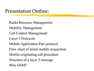
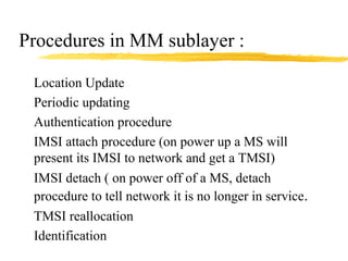
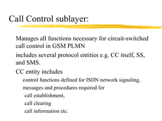
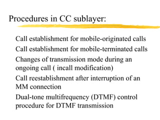
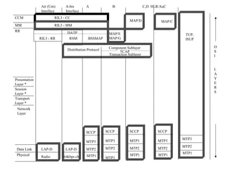
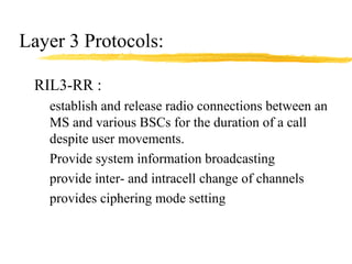
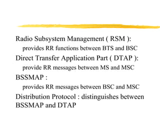
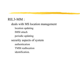
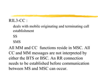
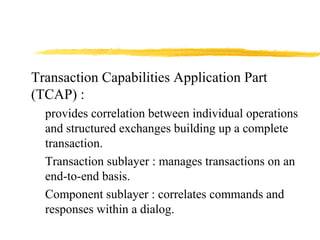
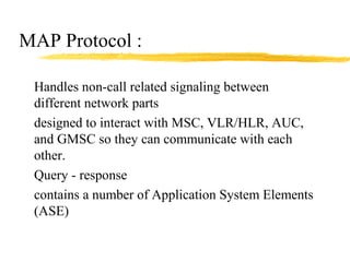
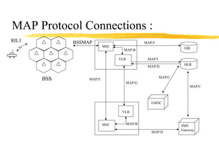
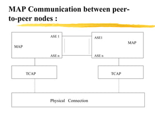
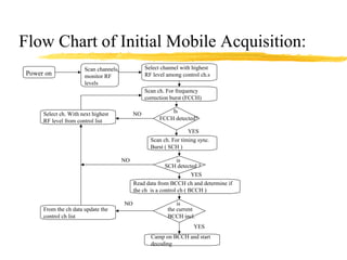
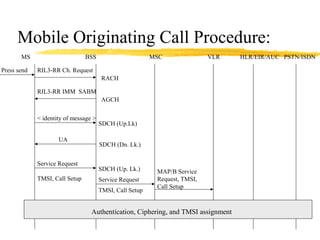
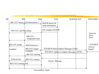
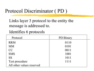
GSM : The Network Layer
Rasha Morsi
Presentation Outline:
Radio Resource Management
Mobility Management
Call Control Management
Layer 3 Protocols
Mobile Application Part protocol
Flow chart of initial mobile acquisition
Mobile originating call procedure
Structure of a layer 3 message
Why GSM?
Acronyms:
TMSI : Temporary Mobile Subscriber Identity
IMSI : International Mobile Subscriber Identity
BCCH : Broadcast Control Channel
FCCH : Frequency Correction Channel
SCH : Synchronization Channel
RACH : Random Access Channel
AGCH :Access Grant Channel
SDCH : Stand-alone Dedicated Control Channel
SABM: Set Asynchronous Balanced Mode
Acronyms (cnt’d)
RIL3 : Radio Interface Layer 3
MAP : Mobile Application Part
UA : Unnumbered Acknowledge
TUP : Telephone User Part
ISUP : ISDN User Part
TCH : Tariff Channel
ACCH: Associated Control Channel
BSSMAP : BSS Management Part
SCCP : Signaling Connection Control Part
RIL3 - CC
RIL3 - MM
CCM
MM
RR
Air (Um)
Interface
A-bis
Interface
MAP/E
MAP/G
MAP/D
DATP
RIL3 - RR RSM BSSMAP
Distribution Protocol
TCAP
Component Sublayer
Transaction Sublayer
A B C,D HLR/AuC
MAP/C
Presentation
Layer *
Session
Layer *
Transport
Layer *
Network
Layer
Physical
Data Link LAP-D
Radio
LAP-D
64kbps ch
SCCP
MTP3
MTP2
MTP1
SCCP
MTP3
MTP2
MTP1
SCCP
MTP3
MTP2
MTP1
SCCP
MTP3
MTP2
MTP1
MTP3
MTP2
MTP1
TUP,
ISUP
O
S
I
L
A
Y
E
R
S
Radio Resource Management sublayer:
Tasks closely related to physical layer
management of frequency spectrum
everything to do with maintaining a clear
channel between PLMN and MS
Handles all procedures necessary to establish,
maintain and release dedicated radio channels
Procedures in RR layer:
Channel assignment
Channel release
Channel change and handover
Change of channel frequencies, hopping sequences
(algorithms) and frequency tables
Measurement reports from the MS
Power control and Time advance
Modification of channel modes (speech and data)
Cipher mode setting
Mobility Management sublayer:
Cope with all effects of handling a mobile user
that are not directly related to radio functions.
Support of user mobility, registration, and
management of mobility data
checking user and equipment identity
user allowed to use services ? Extra services
allowed ?
Support user confidentiality ( register user under a
TMSI)
Provision of user security
Provision of an MM connection, based on existing
RR connection, to the CM sublayer
Procedures in MM sublayer :
Location Update
Periodic updating
Authentication procedure
IMSI attach procedure (on power up a MS will
present its IMSI to network and get a TMSI)
IMSI detach ( on power off of a MS, detach
procedure to tell network it is no longer in service.
TMSI reallocation
Identification
Call Control sublayer:
Manages all functions necessary for circuit-switched
call control in GSM PLMN
includes several protocol entities e.g. CC itself, SS,
and SMS.
CC entity includes
control functions defined for ISDN network signaling,
messages and procedures required for
call establishment,
call clearing
call information etc.
Procedures in CC sublayer:
Call establishment for mobile-originated calls
Call establishment for mobile-terminated calls
Changes of transmission mode during an
ongoing call ( incall modification)
Call reestablishment after interruption of an
MM connection
Dual-tone multifrequency (DTMF) control
procedure for DTMF transmission
RIL3 - CC
RIL3 - MM
CCM
MM
RR
Air (Um)
Interface
A-bis
Interface
MAP/E
MAP/G
MAP/D
DATP
RIL3 - RR RSM BSSMAP
Distribution Protocol
TCAP
Component Sublayer
Transaction Sublayer
A B C,D HLR/AuC
MAP/C
Presentation
Layer *
Session
Layer *
Transport
Layer *
Network
Layer
Physical
Data Link LAP-D
Radio
LAP-D
64kbps ch
SCCP
MTP3
MTP2
MTP1
SCCP
MTP3
MTP2
MTP1
SCCP
MTP3
MTP2
MTP1
SCCP
MTP3
MTP2
MTP1
MTP3
MTP2
MTP1
TUP,
ISUP
O
S
I
L
A
Y
E
R
S
Layer 3 Protocols:
RIL3-RR :
establish and release radio connections between an
MS and various BSCs for the duration of a call
despite user movements.
Provide system information broadcasting
provide inter- and intracell change of channels
provides ciphering mode setting
Radio Subsystem Management ( RSM ):
provides RR functions between BTS and BSC
Direct Transfer Application Part ( DTAP ):
provide RR messages between MS and MSC
BSSMAP :
provides RR messages between BSC and MSC
Distribution Protocol : distinguishes between
BSSMAP and DTAP
RIL3-MM :
deals with MS location management
location updating
IMSI attach
periodic updating
security aspects of system
authentication
TMSI reallocation
identification.
RIL3-CC :
deals with mobile originating and terminating call
establishment
SS
SMS
All MM and CC functions reside in MSC. All
CC and MM messages are not interpreted by
either the BTS or BSC. An RR connection
needs to be established before communication
between MS and MSC can occur.
RIL3 - CC
RIL3 - MM
CCM
MM
RR
Air (Um)
Interface
A-bis
Interface
MAP/E
MAP/G
MAP/D
DATP
RIL3 - RR RSM BSSMAP
Distribution Protocol
TCAP
Component Sublayer
Transaction Sublayer
A B C,D HLR/AuC
MAP/C
Presentation
Layer *
Session
Layer *
Transport
Layer *
Network
Layer
Physical
Data Link LAP-D
Radio
LAP-D
64kbps ch
SCCP
MTP3
MTP2
MTP1
SCCP
MTP3
MTP2
MTP1
SCCP
MTP3
MTP2
MTP1
SCCP
MTP3
MTP2
MTP1
MTP3
MTP2
MTP1
TUP,
ISUP
O
S
I
L
A
Y
E
R
S
Transaction Capabilities Application Part
(TCAP) :
provides correlation between individual operations
and structured exchanges building up a complete
transaction.
Transaction sublayer : manages transactions on an
end-to-end basis.
Component sublayer : correlates commands and
responses within a dialog.
MAP Protocol :
Handles non-call related signaling between
different network parts
designed to interact with MSC, VLR/HLR, AUC,
and GMSC so they can communicate with each
other.
Query - response
contains a number of Application System Elements
(ASE)
all messages contain either mandatory or optional
application parameters.
Functions can be grouped into two categories:
MM and
basic service support.
MAP Protocol Connections :
RIL3
BSS
BSSMAP
MAP/B
VLR
MSC EIR
HLR
GMSC
SMS
Gateway
MAP/C
MAP/C
MAP/I
MAP/D
MAP/F
VLR
MSC
MAP/H
MAP/B
MAP/E
MAP/G
MAP Communication between peer-
to-peer nodes :
ASE1
ASE n
ASE 1
ASE n
MAP
MAP
TCAP TCAP
Physical Connection
Flow Chart of Initial Mobile Acquisition:
Power on
Scan channels,
monitor RF
levels
Select channel with highest
RF level among control ch.s
Scan ch. For frequency
correction burst (FCCH)
Is
FCCH detected?
NO
YES
Scan ch. For timing sync.
Burst ( SCH )
Select ch. With next highest
RF level from control list
is
SCH detected ?
NO
YES
Read data from BCCH ch and determine if
the ch is a control ch ( BCCH )
is
the current
BCCH incl.
YES
NO
From the ch data update the
control ch list
Camp on BCCH and start
decoding
Mobile Originating Call Procedure:
MS BSS MSC VLR HLR/EIR/AUC PSTN/ISDN
Press send RIL3-RR Ch. Request
RACH
RIL3-RR IMM SABM
AGCH
< identity of message >
SDCH (Up.Lk)
UA
SDCH (Dn. Lk.)
Service Request
TMSI, Call Setup
SDCH (Up. Lk.)
Service Request
TMSI, Call Setup
MAP/B Service
Request, TMSI,
Call Setup
Authentication, Ciphering, and TMSI assignment
MS BSS MSC VLR HLR/EIR/AUC PSTN/ISDN
RIL3-CC Setup ( Call Information ) MAP/B Send Call
setup information
Call complete MAP/B
RIL3-CC
Assignment cmd
RIL3-CC assign.
complete
SDCH (Up.Lk.)
RIL3-CC assign
complete
TUP/ISUP Initial Address Message ( IAM )
“ TUP/ISUP
Answer
Signal”
TUP/ISUP Address Complete Message ( ACM )
RIL3-CC alerting
Answer Message
RIL3-CC connectTCH/ACCH
RIL3-CC Connect Ack.
Conversation Starts
RIL3-CC call Proceeding
Subscriber
Phone
Rings
Structure of a layer 3 message:
CRC
Address field
Control field
Length indicator field
Information field
1
2
3
4
.
.
.
10
11
12
Layer 2 Format type B
8 7 6 5 4 3 2 1 Octet Bit 8 7 6 5 4 3 2 1 Octet
Information Elements
“ mandatory ”
Information Elements
“ optional ”
0 Message Type
TI
flag
TI Protocol
Discriminator
Structure of a GSM layer 3 message
Transaction Identifier ( TI ) :
Used to distinguish between possible (multiple) parallel
CC connections and between various transactions taking
place over these simultaneous CC connections.
TI not relevant for RR and MM connections ( coded “
0000” )
TI flag : indicates originator of a CC message ‘0’ by
originator and coded ‘1’ by its peer entity
originator fills in TI value. Kept and serves as a label
during transaction
Protocol Discriminator ( PD )
Links layer 3 protocol to the entity the
message is addressed to.
Identifies 6 protocols
Protocol PD Binary
RRM 0110
MM 0101
CC 0011
SMS 1001
SS 1011
Test procedure 1111
All other values reserved
Message Type :
MT indicates the function of layer 3 message.
Uses lower 6 bits ( 64 possible message types)
for a protocol type indicated by PD.
MT is part of a set of messages in a protocol
Bit 8 = 0 ( reserved )
Bit 7 = send sequence variable and may be
used for MM and CC messages.
Information Elements (IE):
Depending on MT, may
or may not have one or
more IE
Types of IE :
Mandatory fixed length
( MF )
Mandatory variable
length ( MV)
Optional Fixed Length
(OF)
OV
Information Elements
“ mandatory ”
Information Elements
“ optional ”
0 Message Type
TI
flag
TI Protocol
Discriminator
Structure of a GSM layer 3 message
Why GSM ?
Digital
High audio quality and link integrity
High spectral efficiency
Identical system in all countries
Intersystem Roaming
High degree of flexibility ( open architecture
that will allow new services to be introduced
in the future.
Economy in both sparsely and heavily
populated areas
Integration with ISDN
Other security features
SMS and use of facsimile features
Easy to introduce the system
Low-cost infrastructure
References:
GSM System Engineering, Asha Mehrotra,
Artech House Publishers, 1997
An Introduction To GSM, Redl, Weber,
Oliphant, Artech House Publishers, 1995

GSM - The Network Layer

  • 1.
    GSM : TheNetwork Layer Rasha Morsi
  • 2.
    Presentation Outline: Radio ResourceManagement Mobility Management Call Control Management Layer 3 Protocols Mobile Application Part protocol Flow chart of initial mobile acquisition Mobile originating call procedure Structure of a layer 3 message Why GSM?
  • 3.
    Acronyms: TMSI : TemporaryMobile Subscriber Identity IMSI : International Mobile Subscriber Identity BCCH : Broadcast Control Channel FCCH : Frequency Correction Channel SCH : Synchronization Channel RACH : Random Access Channel AGCH :Access Grant Channel SDCH : Stand-alone Dedicated Control Channel SABM: Set Asynchronous Balanced Mode
  • 4.
    Acronyms (cnt’d) RIL3 :Radio Interface Layer 3 MAP : Mobile Application Part UA : Unnumbered Acknowledge TUP : Telephone User Part ISUP : ISDN User Part TCH : Tariff Channel ACCH: Associated Control Channel BSSMAP : BSS Management Part SCCP : Signaling Connection Control Part
  • 5.
    RIL3 - CC RIL3- MM CCM MM RR Air (Um) Interface A-bis Interface MAP/E MAP/G MAP/D DATP RIL3 - RR RSM BSSMAP Distribution Protocol TCAP Component Sublayer Transaction Sublayer A B C,D HLR/AuC MAP/C Presentation Layer * Session Layer * Transport Layer * Network Layer Physical Data Link LAP-D Radio LAP-D 64kbps ch SCCP MTP3 MTP2 MTP1 SCCP MTP3 MTP2 MTP1 SCCP MTP3 MTP2 MTP1 SCCP MTP3 MTP2 MTP1 MTP3 MTP2 MTP1 TUP, ISUP O S I L A Y E R S
  • 6.
    Radio Resource Managementsublayer: Tasks closely related to physical layer management of frequency spectrum everything to do with maintaining a clear channel between PLMN and MS Handles all procedures necessary to establish, maintain and release dedicated radio channels
  • 7.
    Procedures in RRlayer: Channel assignment Channel release Channel change and handover Change of channel frequencies, hopping sequences (algorithms) and frequency tables Measurement reports from the MS Power control and Time advance Modification of channel modes (speech and data) Cipher mode setting
  • 8.
    Mobility Management sublayer: Copewith all effects of handling a mobile user that are not directly related to radio functions. Support of user mobility, registration, and management of mobility data checking user and equipment identity user allowed to use services ? Extra services allowed ? Support user confidentiality ( register user under a TMSI)
  • 9.
    Provision of usersecurity Provision of an MM connection, based on existing RR connection, to the CM sublayer
  • 10.
    Procedures in MMsublayer : Location Update Periodic updating Authentication procedure IMSI attach procedure (on power up a MS will present its IMSI to network and get a TMSI) IMSI detach ( on power off of a MS, detach procedure to tell network it is no longer in service. TMSI reallocation Identification
  • 11.
    Call Control sublayer: Managesall functions necessary for circuit-switched call control in GSM PLMN includes several protocol entities e.g. CC itself, SS, and SMS. CC entity includes control functions defined for ISDN network signaling, messages and procedures required for call establishment, call clearing call information etc.
  • 12.
    Procedures in CCsublayer: Call establishment for mobile-originated calls Call establishment for mobile-terminated calls Changes of transmission mode during an ongoing call ( incall modification) Call reestablishment after interruption of an MM connection Dual-tone multifrequency (DTMF) control procedure for DTMF transmission
  • 13.
    RIL3 - CC RIL3- MM CCM MM RR Air (Um) Interface A-bis Interface MAP/E MAP/G MAP/D DATP RIL3 - RR RSM BSSMAP Distribution Protocol TCAP Component Sublayer Transaction Sublayer A B C,D HLR/AuC MAP/C Presentation Layer * Session Layer * Transport Layer * Network Layer Physical Data Link LAP-D Radio LAP-D 64kbps ch SCCP MTP3 MTP2 MTP1 SCCP MTP3 MTP2 MTP1 SCCP MTP3 MTP2 MTP1 SCCP MTP3 MTP2 MTP1 MTP3 MTP2 MTP1 TUP, ISUP O S I L A Y E R S
  • 14.
    Layer 3 Protocols: RIL3-RR: establish and release radio connections between an MS and various BSCs for the duration of a call despite user movements. Provide system information broadcasting provide inter- and intracell change of channels provides ciphering mode setting
  • 15.
    Radio Subsystem Management( RSM ): provides RR functions between BTS and BSC Direct Transfer Application Part ( DTAP ): provide RR messages between MS and MSC BSSMAP : provides RR messages between BSC and MSC Distribution Protocol : distinguishes between BSSMAP and DTAP
  • 16.
    RIL3-MM : deals withMS location management location updating IMSI attach periodic updating security aspects of system authentication TMSI reallocation identification.
  • 17.
    RIL3-CC : deals withmobile originating and terminating call establishment SS SMS All MM and CC functions reside in MSC. All CC and MM messages are not interpreted by either the BTS or BSC. An RR connection needs to be established before communication between MS and MSC can occur.
  • 18.
    RIL3 - CC RIL3- MM CCM MM RR Air (Um) Interface A-bis Interface MAP/E MAP/G MAP/D DATP RIL3 - RR RSM BSSMAP Distribution Protocol TCAP Component Sublayer Transaction Sublayer A B C,D HLR/AuC MAP/C Presentation Layer * Session Layer * Transport Layer * Network Layer Physical Data Link LAP-D Radio LAP-D 64kbps ch SCCP MTP3 MTP2 MTP1 SCCP MTP3 MTP2 MTP1 SCCP MTP3 MTP2 MTP1 SCCP MTP3 MTP2 MTP1 MTP3 MTP2 MTP1 TUP, ISUP O S I L A Y E R S
  • 19.
    Transaction Capabilities ApplicationPart (TCAP) : provides correlation between individual operations and structured exchanges building up a complete transaction. Transaction sublayer : manages transactions on an end-to-end basis. Component sublayer : correlates commands and responses within a dialog.
  • 20.
    MAP Protocol : Handlesnon-call related signaling between different network parts designed to interact with MSC, VLR/HLR, AUC, and GMSC so they can communicate with each other. Query - response contains a number of Application System Elements (ASE)
  • 21.
    all messages containeither mandatory or optional application parameters. Functions can be grouped into two categories: MM and basic service support.
  • 22.
    MAP Protocol Connections: RIL3 BSS BSSMAP MAP/B VLR MSC EIR HLR GMSC SMS Gateway MAP/C MAP/C MAP/I MAP/D MAP/F VLR MSC MAP/H MAP/B MAP/E MAP/G
  • 23.
    MAP Communication betweenpeer- to-peer nodes : ASE1 ASE n ASE 1 ASE n MAP MAP TCAP TCAP Physical Connection
  • 24.
    Flow Chart ofInitial Mobile Acquisition: Power on Scan channels, monitor RF levels Select channel with highest RF level among control ch.s Scan ch. For frequency correction burst (FCCH) Is FCCH detected? NO YES Scan ch. For timing sync. Burst ( SCH ) Select ch. With next highest RF level from control list is SCH detected ? NO YES Read data from BCCH ch and determine if the ch is a control ch ( BCCH ) is the current BCCH incl. YES NO From the ch data update the control ch list Camp on BCCH and start decoding
  • 25.
    Mobile Originating CallProcedure: MS BSS MSC VLR HLR/EIR/AUC PSTN/ISDN Press send RIL3-RR Ch. Request RACH RIL3-RR IMM SABM AGCH < identity of message > SDCH (Up.Lk) UA SDCH (Dn. Lk.) Service Request TMSI, Call Setup SDCH (Up. Lk.) Service Request TMSI, Call Setup MAP/B Service Request, TMSI, Call Setup Authentication, Ciphering, and TMSI assignment
  • 26.
    MS BSS MSCVLR HLR/EIR/AUC PSTN/ISDN RIL3-CC Setup ( Call Information ) MAP/B Send Call setup information Call complete MAP/B RIL3-CC Assignment cmd RIL3-CC assign. complete SDCH (Up.Lk.) RIL3-CC assign complete TUP/ISUP Initial Address Message ( IAM ) “ TUP/ISUP Answer Signal” TUP/ISUP Address Complete Message ( ACM ) RIL3-CC alerting Answer Message RIL3-CC connectTCH/ACCH RIL3-CC Connect Ack. Conversation Starts RIL3-CC call Proceeding Subscriber Phone Rings
  • 27.
    Structure of alayer 3 message: CRC Address field Control field Length indicator field Information field 1 2 3 4 . . . 10 11 12 Layer 2 Format type B 8 7 6 5 4 3 2 1 Octet Bit 8 7 6 5 4 3 2 1 Octet Information Elements “ mandatory ” Information Elements “ optional ” 0 Message Type TI flag TI Protocol Discriminator Structure of a GSM layer 3 message
  • 28.
    Transaction Identifier (TI ) : Used to distinguish between possible (multiple) parallel CC connections and between various transactions taking place over these simultaneous CC connections. TI not relevant for RR and MM connections ( coded “ 0000” ) TI flag : indicates originator of a CC message ‘0’ by originator and coded ‘1’ by its peer entity originator fills in TI value. Kept and serves as a label during transaction
  • 29.
    Protocol Discriminator (PD ) Links layer 3 protocol to the entity the message is addressed to. Identifies 6 protocols Protocol PD Binary RRM 0110 MM 0101 CC 0011 SMS 1001 SS 1011 Test procedure 1111 All other values reserved
  • 30.
    Message Type : MTindicates the function of layer 3 message. Uses lower 6 bits ( 64 possible message types) for a protocol type indicated by PD. MT is part of a set of messages in a protocol Bit 8 = 0 ( reserved ) Bit 7 = send sequence variable and may be used for MM and CC messages.
  • 31.
    Information Elements (IE): Dependingon MT, may or may not have one or more IE Types of IE : Mandatory fixed length ( MF ) Mandatory variable length ( MV) Optional Fixed Length (OF) OV Information Elements “ mandatory ” Information Elements “ optional ” 0 Message Type TI flag TI Protocol Discriminator Structure of a GSM layer 3 message
  • 32.
    Why GSM ? Digital Highaudio quality and link integrity High spectral efficiency Identical system in all countries Intersystem Roaming High degree of flexibility ( open architecture that will allow new services to be introduced in the future.
  • 33.
    Economy in bothsparsely and heavily populated areas Integration with ISDN Other security features SMS and use of facsimile features Easy to introduce the system Low-cost infrastructure
  • 34.
    References: GSM System Engineering,Asha Mehrotra, Artech House Publishers, 1997 An Introduction To GSM, Redl, Weber, Oliphant, Artech House Publishers, 1995

Editor's Notes

  • #25 1 ) MS scans 124 RF channels may take several seconds ( average of sig. Strength is needed. 2 ) FCCH present ?? 1st step to freq. Synch. Frequency correction burst is unique and easily recognisable It’s a long sine wave that is offset by 67.7 kHz from the carrier freq. The cell transmits all zero’s for this burst . MS has to extract the offset before an estimate of carrier freq. Can be made. 3 ) Occurs 8 burst periods later than FCCH SCH message contains the current frame number the MS is synchronized to.
  • #27 RIL3 CC setup message contains : MS-ISDN number number of called party type of service requested. MAP/B Send Call setup information contains : information of what is desired If Ms authorized, VLR responds with MAP/B Call complete message listing : MS capabilities subscribed services parameters needed bu network to properly allocate a channel for the call. TCH assignment through RIL3-CC assignment cmd. RIL3-CC alerting : informs that desired party is ringing MSC establishes the two way communication.
  • #32 There are distinct definitions for the different MT s each decides which IE s if any must be present in a message. Optional IE s if present are after the mandatory IE s Optional IE s always have to have an information element identifier ( IEI ) tells the receiver of the message the purpose of the info. Contained therein. Inside IE field : page mode channel description request reference timing advance mobile allocation