Downloaded 10 times


![Direct memory addressing mode-
In this mode, address of the operand is directly specified in the instruction. Here only
the offset address is specified, the segment being indicated by the instruction.
Example:
MOV CL, [4321H]
This instruction moves data from location 4321H in the data segment into CL.
The physical address is calculated as
DS * 10H + 4321
Assume DS = 5000H
∴PA = 50000 + 4321 = 54321H
∴CL ← [54321H]
Addressing Modes of 8086](https://image.slidesharecdn.com/5thlab-200703113837/85/8086-Micro-processor-and-MDA-8086-Trainer-Kit-32-320.jpg)
![Register based indirect addressing mode-
In this mode, the effective address of the memory may be taken directly from one of the base
register or index register specified by instruction. If register is SI, DI and BX then DS is by
default segment register.
If BP is used, then SS is by default segment register.
Example:
MOV CX, [BX]
This instruction moves a word from the address pointed by BX and BX + 1 in data segment
into CL and CH respectively.
CL ← DS: [BX] and CH ← DS: [BX + 1]
Physical address can be calculated as DS * 10H + BX.
Register relative addressing mode-
In this mode, the operand address is calculated using one of the base registers and an 8 bit or
a 16 bit displacement.
Example:
MOV CL, [BX + 04H]
This instruction moves a byte from the address pointed by BX + 4 in data segment to CL.
CL ← DS: [BX + 04H]
Physical address can be calculated as DS * 10H + BX + 4H.
Addressing Modes of 8086](https://image.slidesharecdn.com/5thlab-200703113837/85/8086-Micro-processor-and-MDA-8086-Trainer-Kit-33-320.jpg)
![Base indexed addressing mode-
Here, operand address is calculated as base register plus an index register.
Example:
MOV CL, [BX + SI]
This instruction moves a byte from the address pointed by BX + SI in data segment to CL.
CL ← DS: [BX + SI]
Physical address can be calculated as DS * 10H + BX + SI.
Relative based indexed addressing mode-
In this mode, the address of the operand is calculated as the sum of base register, index
register and 8 bit or 16 bit displacement.
Example:
MOV CL, [BX + DI + 20]
This instruction moves a byte from the address pointed by BX + DI + 20H in data segment
to CL.
CL ← DS: [BX + DI + 20H]
Physical address can be calculated as DS * 10H + BX + DI + 20H.
Addressing Modes of 8086](https://image.slidesharecdn.com/5thlab-200703113837/85/8086-Micro-processor-and-MDA-8086-Trainer-Kit-34-320.jpg)


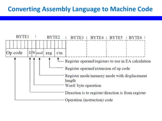


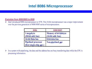
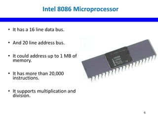
The document discusses the Intel 8086 microprocessor. It provides details on its key features such as being a 16-bit chip released in 1978 with a max clock speed of 5-10 MHz. It describes the 8086's internal architecture including its data bus, address bus, and pin diagram. It also covers the various addressing modes of the 8086 like immediate, register, direct memory, register indirect, register relative, base indexed, and relative indexed addressing. The document concludes with sections on the 8086 instruction set and an example of converting assembly language to machine code.