The document provides information about the 8086 microprocessor including its registers, programming model, stack, pin details, and multiprocessor configurations. It discusses the following key points in 3 sentences:
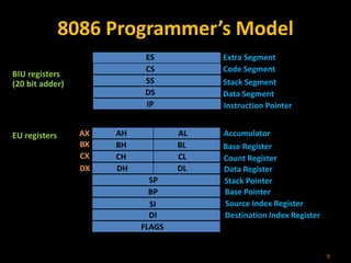
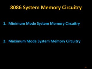
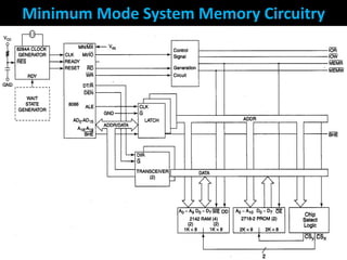
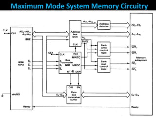
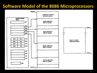
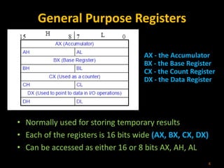
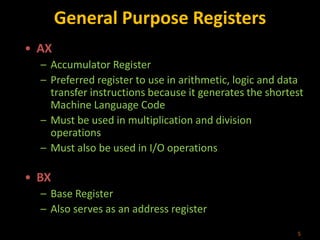
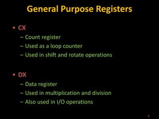
The 8086 has general purpose registers (AX, BX, CX, DX) that can be used for temporary storage and operations. It uses a segmented memory model with code, stack, extra, and data segments. The 8086 can be used in minimum and maximum mode systems with different memory and I/O interfacing depending on the configuration.
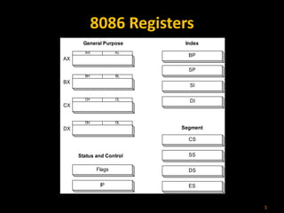
![Pointer and Index Registers
• All 16 bits wide, L/H bytes are not accessible
• Used as memory pointers
– Example: MOV AH, [SI]
• Move the byte stored in memory location whose address is contained in
register SI to register AH
• IP is not under direct control of the programmer
7](https://image.slidesharecdn.com/8086architecture-221027091601-4a6b5232/85/8086_architecture-ppt-7-320.jpg)