1. 12/28/2021
5
12/28/2021
Asst. Prof. Pradip Sah/IOE, Thapathali
Campus
17 12/28/2021
Asst. Prof. Pradip Sah/IOE, Thapathali
Campus
18
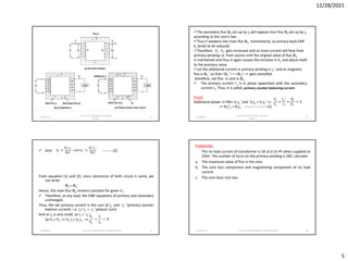
The secondary flux Φ2 set up by I2 will oppose men flux Φo set up by Io
according to the Lenz’s law .
Thus it weakens the main flux Φo momentarily, so primary back EMF
E1 tends to be reduced.
Therefore, V1 - E1 gets increased and so more current will flow from
primary winding i.e. from source until the original value of flux Φo
is maintained and thus it again causes the increase in E1 and adjust itself
to the previous value .
Let the additional current in primary winding is I2 ' and its magnetic
flux is Φ2 ‘ so that I Φ2 ‘ I = I Φ2 I => gets cancelled.
therefore, net flux in core is Φo .
The primary current I’2 is in phase opposition with the secondary
current I2. Thus, it is called primary counter-balancing current.
Proof:
Additional power in PW= V1I2 ‘ and V2I2 = V1I2 ‘ =>
=> N1I’2 = N2I2 -------------------(1)
And ---------(2)
From equation (1) and (2), since reluctance of both circuit is same, we
can write
Φ2 = Φ2 ‘
Hence, the main flux Φo remains constant for given V1 .
Therefore, at any load, the EMF equations of primary and secondary
unchanged.
Thus, the net primary current is the sum of Io and I2 ‘ (primary counter
balance current) i.e. I1= Io + I2 ‘ (phasor sum)
And as Io is very small, so I1 ≈ I2 ‘
So P1 = P2 => V1 I1 = V2 I2 =>
12/28/2021 Asst. Prof. Pradip Sah/IOE, Thapathali Campus 19
Problem#1:
The no load current of transformer is 5A at 0.25 PF when supplied at
235V. The number of turns on the primary winding is 200. calculate
a. The maximum value of flux in the core.
b. The core loss component and magnetizing component of no load
current .
c. The core loss/ iron loss.
12/28/2021 Asst. Prof. Pradip Sah/IOE, Thapathali Campus 20
2. 12/28/2021
7
The basic idea behind the transformation is that the value of R’2
should be such that it produces same amount of heat on Primary
side as produced by R2 in secondary side.
Now, heat produced by R2 in secondary wining = I2
2 R2
heat produced by R’2 in primary wining = I’2
2 R’2
so, I’2
2 R’2 = I2
2 R2 => I1
2 R’2 = I2
2 R2 , assuming I’2 = I1 as Io is very small
Hence, R’2 = (I2 /I1)2R2 =R2/K2
i.e.
Similarly, by equating the reactive power on both sides, we get,
Also, primary equivalent of V2 and E2 is,
V’2 =V2/K and E’2 =E2/K=E1
thus,
R01 = R1 + R’2 = Total equivalent resistance referred to primary side
X01 = X1 + X’2 = Total equivalent resistance referred to primary side
Z01 = R01 + jX01 = Total equivalent impedance referred to primary side
12/28/2021 Asst. Prof. Pradip Sah/IOE, Thapathali Campus 25
Thus, Equivalent circuit of transformer referred to primary side.
12/28/2021 Asst. Prof. Pradip Sah/IOE, Thapathali Campus 26
2. Equivalent circuit of transformer referred to secondary side
Similarly, all the parameters of primary can be transferred to
secondary side as follows:
R’1 = K2 R1 , X’1 = K 2 X1 , R’o = K 2 Ro , X’o = K 2 Xo
V’1 = K V1 and E’1 = K E1
R02 = R2 +R’1 = K 2R01 = Total equivalent resistance referred to secondary side
X02 = X2 + X’1 = K2X01 = Total equivalent resistance referred to secondary side
Z02 = R02 + jX02 = Total equivalent impedance referred to secondary side.
12/28/2021 Asst. Prof. Pradip Sah/IOE, Thapathali Campus 27
Phasor diagram
12/28/2021 Asst. Prof. Pradip Sah/IOE, Thapathali Campus 28
3. 12/28/2021
8
Phasor diagram
12/28/2021 Asst. Prof. Pradip Sah/IOE, Thapathali Campus 29
Losses and efficiency of transformer:
The output of transformer is always less than input power, because of
losses occurring in transformer while it transfers power from one circuit to
another circuit.
So, Power input = Losses + Power output
The various losses are:
12/28/2021 Asst. Prof. Pradip Sah/IOE, Thapathali Campus 30
Transformer
Losses
Iron losses or core
losses
(constant loss)
Hysteresis
loss
Eddy current
losses
Copper losses
(Variable losses)
Dielectric and
stray losses
Iron loss is loss due to heating of core and include hysteresis and
eddy current losses. (explain yourself)
Copper loss is loss due to heating of PW and SW and main cause is
the resistance of windings. (explain yourself)
So, copper loss is given by, Pcu=Wcu = I1
2 R1 + I 2
2 R2 = I1
2 R01 = I2
2 R02
It is clear that Cu loss is proportional to square of the current, and
current depends on the load. Hence copper loss in transformer
varies with the load.
Stray and dielectric loss:
The occurrence of these stray losses is due to the presence of
leakage field. The percentage of these losses are very small as
compared to the iron and copper losses so they can be neglected.
Dielectric loss occurs in the insulating material of the transformer
that is in the oil of the transformer, or in the solid insulations.
12/28/2021 Asst. Prof. Pradip Sah/IOE, Thapathali Campus 31
The Efficiency of a transformer can be defined as the output power divided
by the input power.
Also, we can write
12/28/2021 Asst. Prof. Pradip Sah/IOE, Thapathali Campus 32
4. 12/28/2021
10
Voltage regulation of Transformer:
“Voltage regulation is defined as the change in magnitude of secondary
terminal voltage when full load is reduced to no load, with primary voltage
held constant.”
Mathematically,
Where, V2
NL = no load terminal voltage
V2
FL = full load secondary terminal voltage= V2
12/28/2021 Asst. Prof. Pradip Sah/IOE, Thapathali Campus 37
Voltage regulation of Transformer:
Mathematically,
12/28/2021 Asst. Prof. Pradip Sah/IOE, Thapathali Campus 38
Clearly, at no load I2 =0, so that V2
NL = V1 ’ = primary voltage
From above equivalent cirucit, V2
NL > V2
So, V1 ’ = V2+ I2Z02 = V2+ I2(R02 + jX02) = V2+ I2R02 + jI2X02 (phasor sum)
Hence, voltage regulation is given by,
Now, phasor diagram for inductive load case: (I2 lags V2 by Φ2 )
12/28/2021 Asst. Prof. Pradip Sah/IOE, Thapathali Campus 39
OC=OC’ also, OC≈OM as MC’ is small
and OM=OA+AM
Total voltage drop , I2Z02 =AC ≈AM and
AM=AD+DM
From geometry, AD= I2R02Cos Φ2
DM= I2X02SinΦ2
AM= I2R02Cos Φ2 + I2X02SinΦ2
So, voltage regulation,
Here, Vr = Rpu = Resistive voltage drop expressed as the percentage of
full load voltage. = Per unit resistance
Vx = Rpu = Reactive voltage drop expressed as the percentage of
full load voltage = Per unit reactance.
is known as percentage impedance.
12/28/2021 Asst. Prof. Pradip Sah/IOE, Thapathali Campus 40
5. 12/28/2021
12
Now,
Then from phasor diaram, find
Iw = IoCosΦo
Im = IoSinΦo
and then and
Hence, equivalent circuit at no load is drawn as:
12/28/2021 Asst. Prof. Pradip Sah/IOE, Thapathali Campus 45
Short circuit test:
To find the full load copper loss
To calculate series resistance and reactance i.e. R01 , X01 or R02 , X02.
Procedure:
a) Short circuit the LV side (primary side in this case)
b) HV is supplied by reduced voltage so that full load current flows through
the winding which is recorded by ammeter as shown in diagram.
12/28/2021 Asst. Prof. Pradip Sah/IOE, Thapathali Campus 46
The low voltage is approximately 5 to 10% of the normal rated voltage.
The flux is set up in the core of the transformer and this flux is small as
compared to the normal flux.
So, hysteresis loss is negligible because the iron core does not saturate and
eddy current is also negligible due to low magnetic flux in the core.
Hence, iron loss is negligible in this test , so neglected. i.e. Io is neglected.
So, wattmeter measures only the copper loss in the windings.
Let,
Vsc = voltmeter reading ,Isc = ammeter reading ,Wsc = wattmeter reading
Now,
12/28/2021 Asst. Prof. Pradip Sah/IOE, Thapathali Campus 47
The equivalent circuit for short circuit test is shown below:
Thus, from the data obtained from the two tests , we can determine the
parameters of the equivalent circuit.
And once parameters are known, we can draw the equivalent circuit either
referred to primary side or secondary side according to our requirement.
Note: the values calculated in case of open ckt test is on primary side and in
case of short circuit test is on secondary side, so need to convert one of
them while drawing equivalent circuit.
12/28/2021 Asst. Prof. Pradip Sah/IOE, Thapathali Campus 48
6. 12/28/2021
13
Problem#2:
A 50 KVA, 4400/220 V Transformer has R1= 3.45Ω , R2= 0.009 Ω, X1 = 5.2 Ω,
X2 = 0.015 Ω. Calculate
I. Equivalent resistance as referred to primary and secondary.
II. Equivalent reactance as referred to primary and secondary.
III. Equivalent impedance as referred to primary and secondary
IV. Full load copper loss of transformer.
V. If iron loss is 600 Watt, calculate the efficiency of transformer at
a) Full load at unity power factor.
b) At full load at 0.8 power factor lagging.
12/28/2021 Asst. Prof. Pradip Sah/IOE, Thapathali Campus 49
Solution:
12/28/2021 Asst. Prof. Pradip Sah/IOE, Thapathali Campus 50
Solution:
12/28/2021 Asst. Prof. Pradip Sah/IOE, Thapathali Campus 51
Solution:
12/28/2021 Asst. Prof. Pradip Sah/IOE, Thapathali Campus 52
7. 12/28/2021
14
Solution:
12/28/2021 Asst. Prof. Pradip Sah/IOE, Thapathali Campus 53
Problem#:
12/28/2021 Asst. Prof. Pradip Sah/IOE, Thapathali Campus 54
Problem#:
12/28/2021 Asst. Prof. Pradip Sah/IOE, Thapathali Campus 55
Solution:
12/28/2021 Asst. Prof. Pradip Sah/IOE, Thapathali Campus 56
8. 12/28/2021
15
Solution:
12/28/2021 Asst. Prof. Pradip Sah/IOE, Thapathali Campus 57
Auto transformer
Autotransformer is a transformer having only one windings part of this
being common to both primary and secondary side.
such a transformer is particularly economical when the transformation rescue is
very close to unity.
Note: primary and secondary windings are not electrically isolated from each other
as in the case of two winding transformer.
Let, auto transformer having N1number of primary turn and N2 number turn of
secondary turns.
hence winding section BC of N2 turns is common to both the windings.
Let, auto transformer having N1 number of primary turn and N2 number turn of
secondary turns. Hence winding section BC of N2 turns is common to both the
windings.
Let I2= current drawn by the load, I1 = primary current
Then, current in section BC is the vector difference of two current.
now saving in copper
Here, weight of copper is it's proportional to length and area of cross section of
conductor.
Again length of conductor in winding is proportional to its number of turns and cross-
sectional area varies with rated current.
So weight of copper in winding is directly proportional to product of number of turns
and rated current of the winding.
So, weight of coppe in auto transformer is given by
Wa = weight of copper in section AC + weight of copper in section CB
Hence,
For the similar operation of two winding transformer, weight of copper
is proportional to given by
Now, the ratio of the weight of the copper in an auto transformer to the weight of
copper in an ordinary two winiding transformer is given as
9. 12/28/2021
16
Hence, saving in copper is given by
So, Saving of copper = K x weight of copper required for two windings of the
transformer
Hence, saving in copper increases as the transformation ratio approaches
unity.
Hence, saving in copper used in auto transformer is only significant when the
transformation ratio is nearly equal to unity
Advantages:
Less costly and small size.
Better voltage regulation
Low losses as compared to ordinary two winding transformer of the same
rating, so better efficiency.
Disadvantage:
Any undesirable condition at primary will affect the equipment at
secondary (as windings are not electrically isolated),
due to low impedance (less leakage flux) of auto transformer, secondary
short circuit currents are very high,
harmonics generated in the connected equipment will be passed to the
supply.
if the common part of winding (CB) breaks, the transformer action is lost
and full primary voltage appears across the secondary.
Applications of auto transformer:
Auto transformer is used as variac in laboratory or where continuous
variable over broad ranges are required.
Auto transformers with a number of tapping are used for starting
induction and synchronous motors.
Compensating voltage drops by boosting supply voltage in distribution
systems.
It is also used as a voltage regulator
Three phase Transformer
A three phase transformer is used to transfer a large amount of power. Usually
power is generated and distributed in three phase system and three phase
supplies are used in all industrial applications.
Three-phase supplies have many electrical advantages over single-phase
power.
Therefore, three phase transformer is required to step-up and step-down the
voltages at various stages of a power system network.
Asst. Prof. Pradip Sah/IOE, Thapathali Campus
The three phase transformer is constructed
in two ways:
1. Three separate single phase transformer is
suitably connected for three phase
operation.
2. A single three-phase transformer in which
the cores and windings for all the three
phases are merged into a single structure.
1. Three units of Single Phase (1- φ) transformer used as 3-φ Transformer:
Primary Input Secondary output
voltage voltage
Fig. Three units of 1-phase Transformer used as 3 phase transformer (Y/Y connection)
Polarity of each transformer has be considered carefully while connecting the
transformers.
Three starting ends of PW of each transformer is connected respectively to
primary supply, I.e. A, B, C or R1, Y1 , B1
Asst. Prof. Pradip Sah/IOE, Thapathali Campus
10. 12/28/2021
18
1. Star-Star (Y-Y)
Star-star transformer is formed in a 3 phase transformer by connecting one
terminal of each phase of individual side, together.
Note that star connection is most suitable for high voltage small capacity
transformer.
As phase coil is under the pressure of 1/ 3 times of line voltage and line current
equals phase current. So no. of turns per phase is low hence less insulation
required.
Asst. Prof. Pradip Sah/IOE, Thapathali Campus
Terminals of each phase of HV side should
be labeled as capital letters, A, B, C and
those of LV side should be labeled as small
letters a, b, c. Terminal polarities are
indicated by suffixes 1 and 2. Suffix 1’s
indicate similar polarity ends and so do 2’s.
2. Star-Delta OR Wye-Delta (Y-Δ) 3. Delta-Delta (Δ-Δ)
4. Delta-Star OR Delta-Wye (Δ-Y)
Asst. Prof. Pradip Sah/IOE, Thapathali Campus
This delta connection is suitable
for low voltage large capacity
transformer.
Note: detail description self study
5. Open Delta (V-V) Connection:
• Open delta connection can be used when one of the transformers in Δ-Δ bank
is disabled and the service is to be continued until the faulty transformer is
repaired or replaced.
• It can also be used for small three phase loads where installation of full three
transformer bank is un-necessary.
• The total load carrying capacity of open delta connection is 57.7% than that
would be for delta-delta connection.
Asst. Prof. Pradip Sah/IOE, Thapathali Campus
1. Star-Star (Y-Y)
In any of these configurations, there will be a phase difference of 120° between
any two phases.
Asst. Prof. Pradip Sah/IOE, Thapathali Campus