SlideShare a Scribd company logo
1 of 7
Download to read offline
THERMAL FATIGUE FAILURE IN BED EVAPORATOR TUBE OF AN AFBC BOILER
By K.K.Parthiban, B. Tech(IIT-Madras), M.E Thermal Engineering- RECT Trichy
This paper is about a repetitive evaporator tube failure
experienced in an AFBC boiler. The mode of a bed
evaporator tube is generally erosion or overheating or
water side corrosion. But this case was thermal fatigue.
Photo 1 shows the alligator skin like appearance at the
failed portion . Photo 2 shows the internal longitudinal
chain of cracks at 12o
clock position.
The boiler parameters are 15 TPH, 44 kg/cm2
g and
450o
C. It is a coal fired AFBC boiler with two
compartments. It has to meet the electrical load of the
pulp & paper plant and the steam demand of the paper
machine. Initially the plant was required to operate with
single compartment for some period. Once the plant
operation was stabilized, the boiler started operating to
full load, specific bed evaporator tubes of 2nd
compartment both on left and right side of the boiler
started failing.
The failed tube locations are shown in photo 3. There are
inner and outer tubes in this bed tube configuration. Only
inner tubes failed.
The circulation related failures call for detailed review of
trends of boiler parameters. They are mainly,
• Drum pressure fluctuations
• Drum level fluctuations
• Feed water flow at very low level
• Malfunctioning of single / three element level
control
• Gas temperature profile deviations from design
• High desuperheating flow
• Fouling behavior of superheater & furnace and
high FOT and Eco inlet gas temperature
The definite proof for the cause of the Thermal fatigue mechanism could not be established due to
absence of data. The DCS back was not available. Hence it was advised to collect trends on drum
pressure, drum level, eco out water temperature and FCV open%, once the boiler was restarted. Hence
the discussion was done, towards the possible causes of the failure.
Failed tube inspection and the mechanism of failure
The failed tube showed multiple cracks on the top part of the tube. Studs are welded at the bottom and
Photo 1: Cracks in the tube at top side
Photo 2: Inside of failed tube
the top is strained on
thermal fatigue. There
was intermittent flow
inside the tubes in a cycle
manner. The cracks that
have got initiated once
due short overheating
cycles, have grown to
multiple cracks.
Since the bed tubes are
sloped, the steam
blanketing occurs at top
part of the tube, when the
circulation is retarded.
The top part of the tube
will be subject to
marginal overheating and
differential thermal expansion as compared to bottom part of the tube. The overheating leads to break
down of protective iron oxide exposing bare metal.
The heating and cooling cycles repeat due to
fluctuations in circulation rate. The flow tends to
be intermittent as shown in figure 1. The flow rate
of water inside the tubes must be changing in a
cyclic manner. Normally when the starvation is
sustained, the tube fails by overheating / creep
mechanism. When there are cycles, fatigue is the
failure mechanism.
POSSIBLE CYCLING OVERHEATING
MECHANISM
Steam load pattern / drum pressure variation & flashing
The boiler is connected to the extraction cum condensing turbine. The extraction steam is for the paper
mill. The quantity of steam to paper machine ranges from 8 – 12 tons. The condensing flow is
maintained at 3 TPH normally. The capacity of condensation is however 6 TPH maximum. The load
of boiler varies due to paper break / machine breakdown / pulp section shut down. There will be large
pressure drop in drum pressure. For this reason, steam drum size should be increased. In case there is
load throw, the steam generation must be reduced. When the steam flow is required to be restored,
there will be considerable flashing in the stream drum due to sudden drawl. This can lead to steam
bubble formation due to limited water hold up available in the steam drum. There will be swelling of
water and it is called priming. Priming can cause a drop in water circulation to mud drum, from where,
the water is distributed to bed coils and waterwalls. If load variation is frequent, there will be thermal
hydraulic cycles.
Frequent load throw and zero feed water flow
During the period of low load operation, it becomes necessary to bring down the water flow to the
Figure 1: different types of flow patterns
Photo 3: Location of repetitive bed coil failure – boiler left & right
drum. It is possible that
the FCV is closed on
every occasion of the
paper break. When the
FCV is closed for
longer durations, the
steam drum water
would not be in the
state of subcooling.
This can retard the
circulation rate. There
will be steam formation
in the rear set of bank
tubes which are meant
to be downcomers. As
the steaming occurs in
the downcomer tubes,
the downward flow will cease. This can lead to loss of circulation in a cyclic manner. The trends were
not available to review the past data.
Changes from design temperature profile
When the boiler is overloaded, the flue gas flow is more. The heat pick-up pattern at various zone
changes. When there is high excess air operation, the heat pick-up pattern changes. This also affects
the circulation as the rear set of bank tubes
may start steaming at times when the feed
water flow is less.
Positive downcomers
Steam drum & water drum were inspected.
There was a defect in steam drum internal.
The positive downcomers in the front side
boiler bank tubes were covered under the
baffle box. See photo 4 above. The positive
downcomers are insulated from heat input, by
brick work in the gas path. See photo 5. Baffle
box is a place where steam water mixture is
available. Hence the overall circulation rate is
reduced. The 180-rear set of tubes act as
downcomers normally. By normal heat pick
up, these are downcomers, as the water inside
does not reach boiling state. The steam drum
baffle was corrected in this visit itself.
Nose panel heat pick up & high bed temperature
The boiler is provided with nose panel which extends up to the mid of the furnace. The rear wall nose
Photo 4: Positive downcomers in the steam drum
Photo 5: Brick work insulating the end bank tubes
panel views the bed considerably. This can lead to more circulation in the rearwall tubes. Thus, it could
reduce the circulation in the bed tubes because the downcomer pipes are common to the rear part of
the bed coils and rearwall. In the logbook, the bed temperatures were noted to be as high as 950 deg C
when the load was 16 – 16.5 TPH.
Design comparison with similar boiler
As per the boiler maker, there are two other boilers of same design parameters, working elsewhere,
without tube failure. The downcomer and riser arrangements were compared. There was a difference
in downcomer arrangement. After pointing out the difference, the boiler maker corrected the
downcomers.
Why should particular tubes fail?
The reason for the inner coil to fail is the heat flux and its outlet arrangement. The outer tube gets little
more heat. The inner coil length is 1516 mm and the outer coil length is 2162 mm. The steam
generation in the outer coil is more. This can obstruct the flow rate in the inner coil due to arrangement
of stubs in the bed coil outlet header. Every boiler will have a difference in flow in the set of parallel
tubes. Overall circulation is different from individual circulation rate in the various tubes. In this boiler,
the least flow occurs in the inner coils of 3-4-5-6 tubes from furnace rear wall.
We recommended a modification in feed distributor pipe to get
subcooled water to the positive downcomer zone. This was
incorporated immediately by the boiler supplier.
Coal ash fouling and change in heat pick up pattern
The boiler was found to be heavily fouled as per the photos
shared by the plant engineers. Ash was found to bridge
between the bank tubes. Usually bank tubes are clean. It may
be possible that even the rear set of banks are receiving more
heat input than design. Recently the SSH was cleaned to re-
align the SSH tubes. The PSH was found with less fouling. The
bank tubes were found with ash fouling. The load port analysis
report for the recent imported coal showed ash fusion
temperature (AFT) of 1080o
C. Indonesian coals of such low
AFT cause heavy fouling of furnace wall tubes, SH and this
leads to high bank inlet gas temperature. This can make the rear
set of bank tubes to steam. It was advised to remove all the ash
fouling so that the design temperature profile can be achieved.
Indonesian coal effect
The boiler engineers showed some photos taken during shut
down. The bed coil studs were found coated with slag. The air
nozzles were seen capped with molten ash. This is due to low
AFT of the ash of Indonesian coal. There are some important
things to be taken care in Indonesian coal usage. Photo 7: Ash slag over bed coil studs
Photo 6: Plugged air nozzles
• Coal should be procured with AFT above 1300o
C.
• Iron in bed ash should be less than 10%. This is to be checked by magnet. It is necessary to start
the boiler with fresh bed material. From day one, the iron should be monitored, by frequent bed
draining and replacing with iron free bed ash. Magnetic drums are used for this purpose.
• Bed ash bulk density should be below 1400 kg/m3
. The bulk density of fresh bed material is
generally around 1100 -1200 kg/m3
.
• Fines and volatile matter in Indonesian coal lead to high flame at fuel feed points. Bed should be
drained from all drain pipes. Compulsory draining is required at all drain points.
Circulation analysis
The circulation calculations were performed. It was found that the risers & side waterwalls are the
key elements causing more pressure drop. The bed coil inlet velocity was estimated to be 0.5 m/s.
Usually we target for a velocity of 1 m/s. It was advised to change the riser pipe diameter from 100 nb
to 150 nb. This would increase the velocity to 0.7 m/s. However, the riser modifications were not
carried out as there were two reference boilers which were operating without failure for 3 years.
SECOND VISIT
The tube failures did not stop even after the modification of the steam drum internal& the downcomer
arrangement. The drum level control was found to be OK as per the trends received from the plant for
next 3 months. The tubes that were replaced, failed again in the same pattern. The visit for operational
review had become imminent.
The boiler was in operation at the time of visit. To our luck, all the load variations could be seen. The
boiler was being fired with a combination of Indonesian coal & Indian coal.
The mechanism of tube failure could be found out in this visit. Following is the summary of
observations and operational modifications carried out.
1. The boiler was in least load of about 8.5 TPH in the morning hrs. Only pulp section was in
operation. There was no steam requirement at paper machine as the machine was under
maintenance. One compartment was in operation. The 2nd
compartment was in slumped condition.
The feed water flow was coming down to 4.18 TPH in three element control. The minimum FCV
% opening was at 2.38%. The minimum flow bypass valve
opened once. It was advised to take the level control on manual
mode at such low load situation. The startup vent was in open
condition, as the steam generation was more than
consumption. In the operating compartment itself there was
wide bed temperature difference. One bed temperature was at
874o
C and the other was at 790o
C. 84o
C is too large variation.
The bed height in the 1st
compartment was at 340 mmWC. The
oxygen level was at 10.18 % which can be due to passing air
from slumped compartment. The windbox pressure in 2nd
compartment measured 250 mmWC. The damper leakage was
too high. The economiser outlet water temperature was at a
maximum of 210o
C. It was not steaming. The economiser inlet Photo 8: Low bed height operation
gas temperature was at 379 o
C. The drum
level was stable.
2. Then the load was increased to 16 TPH at
around 11 AM. The pulp section and paper
machine were in operation. The coal feed
rate was kept high and fixed in first
compartment. The coal feeding was being
varied to the 2nd
compartment. There were
erratic temperatures in both 1st
compartment & 2nd
compartment due to
this. The operator was advised to keep
equal feed rate in both compartments. He
was reluctant to keep different rpm as the
steam temperature drops below 450o
C. The
bed height was at 350 mmWC in first
compartment. The bed height was at 320
mmWC in 2nd
compartment. There was
large difference in bed temperatures. There
were steam pressure variations. The rpm
was being varied by the operator almost
every minute. But the boiler response was very poor. The oxygen was erratic. It was ranging from
5% to 8%.
3. Around 12 noon, pulp section was stopped. The boiler load was at 12 TPH. The coal feed rates of
compartments were varied without a basis by the boiler operators. In 1st
compartment, the feeder
rpm was at 709 and in the 2nd
compartment the rpm was at 275. The fuel input to the 2nd
compartment was being varied quite a lot. The steam pressure was not under control at all. The bed
temperatures in 1st
compartment were at 866o
C & 738o
C. The bed temperatures in 2nd
compartment
was at 760 & 698 o
C. It was explained to boiler operators, that less bed height would cause this. It
was not a correct practice to vary the feeder rpm only in 2nd
compartment. It was learnt that all
along this was the operational practice. That answered the cycles of circulation disturbance. Every
time when the firing is reduced, the heat input is reduced in 2nd
compartment; the circulation gets
reduced. The circulation takes time to establish back, when the coal feed is increased. This
frequency was high enough to have thermal fatigue. However, FCV % opening was good with 3
element control.
4. After lunch time, operator agreed to feed same coal in both compartments. The erratic bed
temperatures came down a little. The pulp section was down. However, the steam pressure
fluctuation was high. Almost every minute, the boiler operator was adjusting the feeder rpm. The
boiler operation was not stable. The economiser was not steaming. The economiser water outlet
temperature was at 194 o
C. The drum level was quite stable. The FCV opening was above 50%.
Our doubt on low feed water flow was gone. Three element was working quite satisfactorily.
5. The bed height was increased to 400 mmWC. As the bed material feed rate was high, the bed
temperature dropped too much. It was advised to throttle the gate below bed material bunker. The
rear door was opened to see the immersion. 3/4th
of the top part of the outer bed coil was visible.
See photo 10.The bed height could be further increased. It was flameless combustion, which is the
characteristics of fluidised bed.
6. The bed height was further raised to 420 mmWC. The PA header pressure was raised to 1075
mmWC. The vacuum was checked at the mixing nozzle and found to be OK. The feeder rpm was
found to be same at field for both feeders, when the % rpm was kept same at DCS. The bed
Photo 9: Different coal feed rpm & bed temp difference
temperatures & steam pressure
stabilized. The oxygen level
could be held constant at 4.5%.
The paper GSM was at 100.
Only paper machine was
running. Further when the pulp
section was started at around
4.00 PM, the boiler was
stabilized very fast, due to
deep bed operation. Operator
was educated as how to change
the feeder rpm and air flow
proportionately to load. The steam generation went to 15 – 15.8 TPH. The steam temperature was
at 435 o
C with steam pressure at 44 kg/cm2. Operator was advised to target 46 kg/cm2. The oxygen
came under control. The variance in bed temperatures dropped to 27 o
C & 9 o
C. The proximity of
thermocouples to fuel feed point & ash drain point has a say in this variance. There was minor
pressure variation due to variations in steam drawl rate or GCV change of the coal mix.
7. At 6.00 PM, the GSM was changed to 120. Then also the boiler was stable. The operator was
advised to how to proportionately change the air flow and coal feeder rpm. The airbox pressure
was at 535 mmWC. The bed temperatures were at 860 o
C – 890o
C with the load was at 16.5 TPH
and the oxygen was at 4%. The economiser was not steaming. The economiser water outlet
temperature was at 189 o
C. Drum level was stable. The FCV was at 75% open.
8. All operators learnt the advantage of the deeper bed of 425 mmWC. The bed height must be
increased slowly without dropping the bed temperature excessively. The bed material gate at bed
material bunker should have a hole of 50 mm only so that the feed rate is minimum & controlled.
The bed inventory should be more or less constant, like boiler drum level. This is the key to stability
of the combustion in AFBC / CFBC boilers. Flue gas does not transfer heat directly to bed coil. It
is the bed material that transfers the heat to the bed coil. Less bed height causes erratic combustion.
CONCLUSION
The erratic coal feeding had caused disturbed circulation rate. The steam raising in 2nd
compartment
was upset by irregular rpm. The rpm was being kept high & constant in 1st
compartment. This was a
wrong practice. This promoted free board combustion in front half of the furnace. The 2nd
compartment
was put to thermo hydraulic cycles of steam generation due to erratic fuel feed rate. This had caused
the overheating cycles of the tube. The flow was retarded frequently by the changing heat input to 2nd
compartment. Hence there was a thermal fatigue. That was the reason, that this boiler had bed coil
failures, whereas the failure was not experienced in the other two boiler installations.
M/S Venus energy audit system – Trouble shooting of boiler failures and operational
issues. Company carries out design audit, construction audit, shut down audit and
operational audit.
M/S Sri Devi engineering consultancy and agency – engaged in non-pressure parts
spares supply for FBC / CFBC / PF boilers.
M/S Sri Devi boiler equipment and spares – engaged in supply of pressure part spares
for all type of boilers
Photo 10: Bed height increased & yet bed coil visible

More Related Content

What's hot

Deaerator -thermal power plants
Deaerator  -thermal power plantsDeaerator  -thermal power plants
Deaerator -thermal power plantsAshish Kumar Jain
 
Design of superheater for 210 MW thermal powerplant final
Design of superheater for 210 MW thermal powerplant finalDesign of superheater for 210 MW thermal powerplant final
Design of superheater for 210 MW thermal powerplant finalKundan Chakraborty
 
A Brief Introduction to Boilers
A Brief Introduction to BoilersA Brief Introduction to Boilers
A Brief Introduction to BoilersSATYAKAM MOHAPATRA
 
MET 401 Chapter 4 boilers_and_steam_generators
MET 401 Chapter 4 boilers_and_steam_generatorsMET 401 Chapter 4 boilers_and_steam_generators
MET 401 Chapter 4 boilers_and_steam_generatorsIbrahim AboKhalil
 
Normal Operation of Steam Reformers on Hydrogen Plants
Normal Operation of Steam Reformers on Hydrogen PlantsNormal Operation of Steam Reformers on Hydrogen Plants
Normal Operation of Steam Reformers on Hydrogen PlantsGerard B. Hawkins
 
Primary Reforming Flowsheets
Primary Reforming FlowsheetsPrimary Reforming Flowsheets
Primary Reforming FlowsheetsGerard B. Hawkins
 
Steam Boilers OR Steam Generators
Steam Boilers OR Steam GeneratorsSteam Boilers OR Steam Generators
Steam Boilers OR Steam GeneratorsHrishikesh Devan
 
Chemical Cleaning of Boiler in a Thermal Power Plant
Chemical Cleaning of Boiler in a Thermal Power PlantChemical Cleaning of Boiler in a Thermal Power Plant
Chemical Cleaning of Boiler in a Thermal Power PlantSUDHEER KUMAR KALYANAM
 
WUXI MAKE CFBC BOILER COLD CYCLONE
WUXI MAKE CFBC BOILER COLD CYCLONEWUXI MAKE CFBC BOILER COLD CYCLONE
WUXI MAKE CFBC BOILER COLD CYCLONEAshish Kumar Jain
 
Fired Heater Operation and Trouble Shooting.pdf
Fired Heater  Operation and Trouble Shooting.pdfFired Heater  Operation and Trouble Shooting.pdf
Fired Heater Operation and Trouble Shooting.pdfMuhammadNaeem191352
 
Ammonia plant efficiency
Ammonia plant efficiencyAmmonia plant efficiency
Ammonia plant efficiencyHimanshu Sharma
 
Cfbc boiler startup and shutdown
Cfbc boiler startup and shutdownCfbc boiler startup and shutdown
Cfbc boiler startup and shutdownAshvani Shukla
 
Circulating fluidizing bed combustion Boiler presentation
Circulating fluidizing bed combustion Boiler presentation Circulating fluidizing bed combustion Boiler presentation
Circulating fluidizing bed combustion Boiler presentation Sawan Vaja
 
Ammonia Plant - Methanation Operations
Ammonia Plant - Methanation OperationsAmmonia Plant - Methanation Operations
Ammonia Plant - Methanation OperationsGerard B. Hawkins
 
Burner Design, Operation and Maintenance on Ammonia Plants
Burner Design, Operation and Maintenance on Ammonia PlantsBurner Design, Operation and Maintenance on Ammonia Plants
Burner Design, Operation and Maintenance on Ammonia PlantsGerard B. Hawkins
 
Circulating Fluidized Bed Boiler (cfb) training module
Circulating Fluidized Bed Boiler (cfb) training module Circulating Fluidized Bed Boiler (cfb) training module
Circulating Fluidized Bed Boiler (cfb) training module Alexander Ual
 
Ntpc (national thermal power corporation) sipat boiler haxxo24 i~i
Ntpc (national thermal power corporation) sipat boiler haxxo24 i~iNtpc (national thermal power corporation) sipat boiler haxxo24 i~i
Ntpc (national thermal power corporation) sipat boiler haxxo24 i~ihaxxo24
 
Boiler – fundamentals and best practices
Boiler – fundamentals and best practicesBoiler – fundamentals and best practices
Boiler – fundamentals and best practicesBassem Eleaba, MEng
 
U#3 BOILER CHEMICAL CLEANING.
U#3 BOILER CHEMICAL CLEANING.U#3 BOILER CHEMICAL CLEANING.
U#3 BOILER CHEMICAL CLEANING.Dilip Kumar
 

What's hot (20)

Deaerator -thermal power plants
Deaerator  -thermal power plantsDeaerator  -thermal power plants
Deaerator -thermal power plants
 
Design of superheater for 210 MW thermal powerplant final
Design of superheater for 210 MW thermal powerplant finalDesign of superheater for 210 MW thermal powerplant final
Design of superheater for 210 MW thermal powerplant final
 
A Brief Introduction to Boilers
A Brief Introduction to BoilersA Brief Introduction to Boilers
A Brief Introduction to Boilers
 
MET 401 Chapter 4 boilers_and_steam_generators
MET 401 Chapter 4 boilers_and_steam_generatorsMET 401 Chapter 4 boilers_and_steam_generators
MET 401 Chapter 4 boilers_and_steam_generators
 
Normal Operation of Steam Reformers on Hydrogen Plants
Normal Operation of Steam Reformers on Hydrogen PlantsNormal Operation of Steam Reformers on Hydrogen Plants
Normal Operation of Steam Reformers on Hydrogen Plants
 
Primary Reforming Flowsheets
Primary Reforming FlowsheetsPrimary Reforming Flowsheets
Primary Reforming Flowsheets
 
Steam Boilers OR Steam Generators
Steam Boilers OR Steam GeneratorsSteam Boilers OR Steam Generators
Steam Boilers OR Steam Generators
 
Chemical Cleaning of Boiler in a Thermal Power Plant
Chemical Cleaning of Boiler in a Thermal Power PlantChemical Cleaning of Boiler in a Thermal Power Plant
Chemical Cleaning of Boiler in a Thermal Power Plant
 
WUXI MAKE CFBC BOILER COLD CYCLONE
WUXI MAKE CFBC BOILER COLD CYCLONEWUXI MAKE CFBC BOILER COLD CYCLONE
WUXI MAKE CFBC BOILER COLD CYCLONE
 
Fired Heater Operation and Trouble Shooting.pdf
Fired Heater  Operation and Trouble Shooting.pdfFired Heater  Operation and Trouble Shooting.pdf
Fired Heater Operation and Trouble Shooting.pdf
 
Thermax report (1)
Thermax report (1)Thermax report (1)
Thermax report (1)
 
Ammonia plant efficiency
Ammonia plant efficiencyAmmonia plant efficiency
Ammonia plant efficiency
 
Cfbc boiler startup and shutdown
Cfbc boiler startup and shutdownCfbc boiler startup and shutdown
Cfbc boiler startup and shutdown
 
Circulating fluidizing bed combustion Boiler presentation
Circulating fluidizing bed combustion Boiler presentation Circulating fluidizing bed combustion Boiler presentation
Circulating fluidizing bed combustion Boiler presentation
 
Ammonia Plant - Methanation Operations
Ammonia Plant - Methanation OperationsAmmonia Plant - Methanation Operations
Ammonia Plant - Methanation Operations
 
Burner Design, Operation and Maintenance on Ammonia Plants
Burner Design, Operation and Maintenance on Ammonia PlantsBurner Design, Operation and Maintenance on Ammonia Plants
Burner Design, Operation and Maintenance on Ammonia Plants
 
Circulating Fluidized Bed Boiler (cfb) training module
Circulating Fluidized Bed Boiler (cfb) training module Circulating Fluidized Bed Boiler (cfb) training module
Circulating Fluidized Bed Boiler (cfb) training module
 
Ntpc (national thermal power corporation) sipat boiler haxxo24 i~i
Ntpc (national thermal power corporation) sipat boiler haxxo24 i~iNtpc (national thermal power corporation) sipat boiler haxxo24 i~i
Ntpc (national thermal power corporation) sipat boiler haxxo24 i~i
 
Boiler – fundamentals and best practices
Boiler – fundamentals and best practicesBoiler – fundamentals and best practices
Boiler – fundamentals and best practices
 
U#3 BOILER CHEMICAL CLEANING.
U#3 BOILER CHEMICAL CLEANING.U#3 BOILER CHEMICAL CLEANING.
U#3 BOILER CHEMICAL CLEANING.
 

Similar to Thermal fatigue failure in a FBC boiler

Construction of babcock and wilcox boiler
Construction of babcock and wilcox boilerConstruction of babcock and wilcox boiler
Construction of babcock and wilcox boilerAQIB_HAIDER
 
Case studies in boiler vibration and BFP cavitation by k.k.parthiban
Case studies in boiler vibration and BFP cavitation by k.k.parthibanCase studies in boiler vibration and BFP cavitation by k.k.parthiban
Case studies in boiler vibration and BFP cavitation by k.k.parthibanVENUS ENERGY AUDIT SYSTEM
 
Babcock and Wilcox Boiler
Babcock and Wilcox BoilerBabcock and Wilcox Boiler
Babcock and Wilcox Boilerrishironak
 
High pressure boilers (1)
High pressure boilers (1)High pressure boilers (1)
High pressure boilers (1)sneh patel
 
STEAM GENERATORS.pptx
STEAM GENERATORS.pptxSTEAM GENERATORS.pptx
STEAM GENERATORS.pptxssusere6313f
 
Boilers ppt (energy conversion)
Boilers ppt (energy conversion)Boilers ppt (energy conversion)
Boilers ppt (energy conversion)Dinesh Panchal
 
Guide to Furnace Sootblowing
Guide to Furnace SootblowingGuide to Furnace Sootblowing
Guide to Furnace SootblowingRichard Smith
 
All about boilers: Complete Basics, Classification of boilers,types
All about boilers: Complete Basics, Classification of boilers,typesAll about boilers: Complete Basics, Classification of boilers,types
All about boilers: Complete Basics, Classification of boilers,typesHashim Hasnain Hadi
 
Steam Generator or Boilers
Steam Generator or BoilersSteam Generator or Boilers
Steam Generator or BoilersRidwanul Hoque
 
Study of Boilers for Mechanical Engineering
Study of Boilers for Mechanical EngineeringStudy of Boilers for Mechanical Engineering
Study of Boilers for Mechanical EngineeringAbdullahKafi18
 
CORROSION REPORT(refined)
CORROSION REPORT(refined)CORROSION REPORT(refined)
CORROSION REPORT(refined)Jesse Carreau
 
mech 2nd yr lab report.pdf
mech 2nd yr lab report.pdfmech 2nd yr lab report.pdf
mech 2nd yr lab report.pdfMOHDAHMED52
 

Similar to Thermal fatigue failure in a FBC boiler (20)

Construction of babcock and wilcox boiler
Construction of babcock and wilcox boilerConstruction of babcock and wilcox boiler
Construction of babcock and wilcox boiler
 
Case studies in boiler vibration and BFP cavitation by k.k.parthiban
Case studies in boiler vibration and BFP cavitation by k.k.parthibanCase studies in boiler vibration and BFP cavitation by k.k.parthiban
Case studies in boiler vibration and BFP cavitation by k.k.parthiban
 
Babcock and Wilcox Boiler
Babcock and Wilcox BoilerBabcock and Wilcox Boiler
Babcock and Wilcox Boiler
 
High pressure boilers (1)
High pressure boilers (1)High pressure boilers (1)
High pressure boilers (1)
 
STEAM GENERATORS.pptx
STEAM GENERATORS.pptxSTEAM GENERATORS.pptx
STEAM GENERATORS.pptx
 
Boiler turbe failores
Boiler turbe failoresBoiler turbe failores
Boiler turbe failores
 
Boilers ppt (energy conversion)
Boilers ppt (energy conversion)Boilers ppt (energy conversion)
Boilers ppt (energy conversion)
 
Guide to Furnace Sootblowing
Guide to Furnace SootblowingGuide to Furnace Sootblowing
Guide to Furnace Sootblowing
 
Boiler Designs
Boiler Designs Boiler Designs
Boiler Designs
 
All about boilers: Complete Basics, Classification of boilers,types
All about boilers: Complete Basics, Classification of boilers,typesAll about boilers: Complete Basics, Classification of boilers,types
All about boilers: Complete Basics, Classification of boilers,types
 
Engg mech and thermodynamics
Engg mech and thermodynamicsEngg mech and thermodynamics
Engg mech and thermodynamics
 
Engg mech and thermodynamics
Engg mech and thermodynamicsEngg mech and thermodynamics
Engg mech and thermodynamics
 
Steam Generator or Boilers
Steam Generator or BoilersSteam Generator or Boilers
Steam Generator or Boilers
 
Study of Boilers for Mechanical Engineering
Study of Boilers for Mechanical EngineeringStudy of Boilers for Mechanical Engineering
Study of Boilers for Mechanical Engineering
 
Boilers notes.pdf
Boilers notes.pdfBoilers notes.pdf
Boilers notes.pdf
 
Ch.2
Ch.2Ch.2
Ch.2
 
CORROSION REPORT(refined)
CORROSION REPORT(refined)CORROSION REPORT(refined)
CORROSION REPORT(refined)
 
mech 2nd yr lab report.pdf
mech 2nd yr lab report.pdfmech 2nd yr lab report.pdf
mech 2nd yr lab report.pdf
 
GRP X - Activity.pdf
GRP X - Activity.pdfGRP X - Activity.pdf
GRP X - Activity.pdf
 
Cochran boiler presentation
Cochran boiler presentationCochran boiler presentation
Cochran boiler presentation
 

Recently uploaded

VIP Call Girls Service Hitech City Hyderabad Call +91-8250192130
VIP Call Girls Service Hitech City Hyderabad Call +91-8250192130VIP Call Girls Service Hitech City Hyderabad Call +91-8250192130
VIP Call Girls Service Hitech City Hyderabad Call +91-8250192130Suhani Kapoor
 
Internship report on mechanical engineering
Internship report on mechanical engineeringInternship report on mechanical engineering
Internship report on mechanical engineeringmalavadedarshan25
 
What are the advantages and disadvantages of membrane structures.pptx
What are the advantages and disadvantages of membrane structures.pptxWhat are the advantages and disadvantages of membrane structures.pptx
What are the advantages and disadvantages of membrane structures.pptxwendy cai
 
Electronically Controlled suspensions system .pdf
Electronically Controlled suspensions system .pdfElectronically Controlled suspensions system .pdf
Electronically Controlled suspensions system .pdfme23b1001
 
VICTOR MAESTRE RAMIREZ - Planetary Defender on NASA's Double Asteroid Redirec...
VICTOR MAESTRE RAMIREZ - Planetary Defender on NASA's Double Asteroid Redirec...VICTOR MAESTRE RAMIREZ - Planetary Defender on NASA's Double Asteroid Redirec...
VICTOR MAESTRE RAMIREZ - Planetary Defender on NASA's Double Asteroid Redirec...VICTOR MAESTRE RAMIREZ
 
HARMONY IN THE HUMAN BEING - Unit-II UHV-2
HARMONY IN THE HUMAN BEING - Unit-II UHV-2HARMONY IN THE HUMAN BEING - Unit-II UHV-2
HARMONY IN THE HUMAN BEING - Unit-II UHV-2RajaP95
 
Current Transformer Drawing and GTP for MSETCL
Current Transformer Drawing and GTP for MSETCLCurrent Transformer Drawing and GTP for MSETCL
Current Transformer Drawing and GTP for MSETCLDeelipZope
 
GDSC ASEB Gen AI study jams presentation
GDSC ASEB Gen AI study jams presentationGDSC ASEB Gen AI study jams presentation
GDSC ASEB Gen AI study jams presentationGDSCAESB
 
APPLICATIONS-AC/DC DRIVES-OPERATING CHARACTERISTICS
APPLICATIONS-AC/DC DRIVES-OPERATING CHARACTERISTICSAPPLICATIONS-AC/DC DRIVES-OPERATING CHARACTERISTICS
APPLICATIONS-AC/DC DRIVES-OPERATING CHARACTERISTICSKurinjimalarL3
 
CCS355 Neural Network & Deep Learning Unit II Notes with Question bank .pdf
CCS355 Neural Network & Deep Learning Unit II Notes with Question bank .pdfCCS355 Neural Network & Deep Learning Unit II Notes with Question bank .pdf
CCS355 Neural Network & Deep Learning Unit II Notes with Question bank .pdfAsst.prof M.Gokilavani
 
Application of Residue Theorem to evaluate real integrations.pptx
Application of Residue Theorem to evaluate real integrations.pptxApplication of Residue Theorem to evaluate real integrations.pptx
Application of Residue Theorem to evaluate real integrations.pptx959SahilShah
 
IVE Industry Focused Event - Defence Sector 2024
IVE Industry Focused Event - Defence Sector 2024IVE Industry Focused Event - Defence Sector 2024
IVE Industry Focused Event - Defence Sector 2024Mark Billinghurst
 
Past, Present and Future of Generative AI
Past, Present and Future of Generative AIPast, Present and Future of Generative AI
Past, Present and Future of Generative AIabhishek36461
 
Introduction to Microprocesso programming and interfacing.pptx
Introduction to Microprocesso programming and interfacing.pptxIntroduction to Microprocesso programming and interfacing.pptx
Introduction to Microprocesso programming and interfacing.pptxvipinkmenon1
 
Software and Systems Engineering Standards: Verification and Validation of Sy...
Software and Systems Engineering Standards: Verification and Validation of Sy...Software and Systems Engineering Standards: Verification and Validation of Sy...
Software and Systems Engineering Standards: Verification and Validation of Sy...VICTOR MAESTRE RAMIREZ
 
OSVC_Meta-Data based Simulation Automation to overcome Verification Challenge...
OSVC_Meta-Data based Simulation Automation to overcome Verification Challenge...OSVC_Meta-Data based Simulation Automation to overcome Verification Challenge...
OSVC_Meta-Data based Simulation Automation to overcome Verification Challenge...Soham Mondal
 
Microscopic Analysis of Ceramic Materials.pptx
Microscopic Analysis of Ceramic Materials.pptxMicroscopic Analysis of Ceramic Materials.pptx
Microscopic Analysis of Ceramic Materials.pptxpurnimasatapathy1234
 
Oxy acetylene welding presentation note.
Oxy acetylene welding presentation note.Oxy acetylene welding presentation note.
Oxy acetylene welding presentation note.eptoze12
 

Recently uploaded (20)

VIP Call Girls Service Hitech City Hyderabad Call +91-8250192130
VIP Call Girls Service Hitech City Hyderabad Call +91-8250192130VIP Call Girls Service Hitech City Hyderabad Call +91-8250192130
VIP Call Girls Service Hitech City Hyderabad Call +91-8250192130
 
Internship report on mechanical engineering
Internship report on mechanical engineeringInternship report on mechanical engineering
Internship report on mechanical engineering
 
What are the advantages and disadvantages of membrane structures.pptx
What are the advantages and disadvantages of membrane structures.pptxWhat are the advantages and disadvantages of membrane structures.pptx
What are the advantages and disadvantages of membrane structures.pptx
 
Electronically Controlled suspensions system .pdf
Electronically Controlled suspensions system .pdfElectronically Controlled suspensions system .pdf
Electronically Controlled suspensions system .pdf
 
Exploring_Network_Security_with_JA3_by_Rakesh Seal.pptx
Exploring_Network_Security_with_JA3_by_Rakesh Seal.pptxExploring_Network_Security_with_JA3_by_Rakesh Seal.pptx
Exploring_Network_Security_with_JA3_by_Rakesh Seal.pptx
 
VICTOR MAESTRE RAMIREZ - Planetary Defender on NASA's Double Asteroid Redirec...
VICTOR MAESTRE RAMIREZ - Planetary Defender on NASA's Double Asteroid Redirec...VICTOR MAESTRE RAMIREZ - Planetary Defender on NASA's Double Asteroid Redirec...
VICTOR MAESTRE RAMIREZ - Planetary Defender on NASA's Double Asteroid Redirec...
 
HARMONY IN THE HUMAN BEING - Unit-II UHV-2
HARMONY IN THE HUMAN BEING - Unit-II UHV-2HARMONY IN THE HUMAN BEING - Unit-II UHV-2
HARMONY IN THE HUMAN BEING - Unit-II UHV-2
 
Current Transformer Drawing and GTP for MSETCL
Current Transformer Drawing and GTP for MSETCLCurrent Transformer Drawing and GTP for MSETCL
Current Transformer Drawing and GTP for MSETCL
 
GDSC ASEB Gen AI study jams presentation
GDSC ASEB Gen AI study jams presentationGDSC ASEB Gen AI study jams presentation
GDSC ASEB Gen AI study jams presentation
 
APPLICATIONS-AC/DC DRIVES-OPERATING CHARACTERISTICS
APPLICATIONS-AC/DC DRIVES-OPERATING CHARACTERISTICSAPPLICATIONS-AC/DC DRIVES-OPERATING CHARACTERISTICS
APPLICATIONS-AC/DC DRIVES-OPERATING CHARACTERISTICS
 
CCS355 Neural Network & Deep Learning Unit II Notes with Question bank .pdf
CCS355 Neural Network & Deep Learning Unit II Notes with Question bank .pdfCCS355 Neural Network & Deep Learning Unit II Notes with Question bank .pdf
CCS355 Neural Network & Deep Learning Unit II Notes with Question bank .pdf
 
Application of Residue Theorem to evaluate real integrations.pptx
Application of Residue Theorem to evaluate real integrations.pptxApplication of Residue Theorem to evaluate real integrations.pptx
Application of Residue Theorem to evaluate real integrations.pptx
 
POWER SYSTEMS-1 Complete notes examples
POWER SYSTEMS-1 Complete notes  examplesPOWER SYSTEMS-1 Complete notes  examples
POWER SYSTEMS-1 Complete notes examples
 
IVE Industry Focused Event - Defence Sector 2024
IVE Industry Focused Event - Defence Sector 2024IVE Industry Focused Event - Defence Sector 2024
IVE Industry Focused Event - Defence Sector 2024
 
Past, Present and Future of Generative AI
Past, Present and Future of Generative AIPast, Present and Future of Generative AI
Past, Present and Future of Generative AI
 
Introduction to Microprocesso programming and interfacing.pptx
Introduction to Microprocesso programming and interfacing.pptxIntroduction to Microprocesso programming and interfacing.pptx
Introduction to Microprocesso programming and interfacing.pptx
 
Software and Systems Engineering Standards: Verification and Validation of Sy...
Software and Systems Engineering Standards: Verification and Validation of Sy...Software and Systems Engineering Standards: Verification and Validation of Sy...
Software and Systems Engineering Standards: Verification and Validation of Sy...
 
OSVC_Meta-Data based Simulation Automation to overcome Verification Challenge...
OSVC_Meta-Data based Simulation Automation to overcome Verification Challenge...OSVC_Meta-Data based Simulation Automation to overcome Verification Challenge...
OSVC_Meta-Data based Simulation Automation to overcome Verification Challenge...
 
Microscopic Analysis of Ceramic Materials.pptx
Microscopic Analysis of Ceramic Materials.pptxMicroscopic Analysis of Ceramic Materials.pptx
Microscopic Analysis of Ceramic Materials.pptx
 
Oxy acetylene welding presentation note.
Oxy acetylene welding presentation note.Oxy acetylene welding presentation note.
Oxy acetylene welding presentation note.
 

Thermal fatigue failure in a FBC boiler

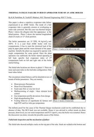
  • 1. THERMAL FATIGUE FAILURE IN BED EVAPORATOR TUBE OF AN AFBC BOILER By K.K.Parthiban, B. Tech(IIT-Madras), M.E Thermal Engineering- RECT Trichy This paper is about a repetitive evaporator tube failure experienced in an AFBC boiler. The mode of a bed evaporator tube is generally erosion or overheating or water side corrosion. But this case was thermal fatigue. Photo 1 shows the alligator skin like appearance at the failed portion . Photo 2 shows the internal longitudinal chain of cracks at 12o clock position. The boiler parameters are 15 TPH, 44 kg/cm2 g and 450o C. It is a coal fired AFBC boiler with two compartments. It has to meet the electrical load of the pulp & paper plant and the steam demand of the paper machine. Initially the plant was required to operate with single compartment for some period. Once the plant operation was stabilized, the boiler started operating to full load, specific bed evaporator tubes of 2nd compartment both on left and right side of the boiler started failing. The failed tube locations are shown in photo 3. There are inner and outer tubes in this bed tube configuration. Only inner tubes failed. The circulation related failures call for detailed review of trends of boiler parameters. They are mainly, • Drum pressure fluctuations • Drum level fluctuations • Feed water flow at very low level • Malfunctioning of single / three element level control • Gas temperature profile deviations from design • High desuperheating flow • Fouling behavior of superheater & furnace and high FOT and Eco inlet gas temperature The definite proof for the cause of the Thermal fatigue mechanism could not be established due to absence of data. The DCS back was not available. Hence it was advised to collect trends on drum pressure, drum level, eco out water temperature and FCV open%, once the boiler was restarted. Hence the discussion was done, towards the possible causes of the failure. Failed tube inspection and the mechanism of failure The failed tube showed multiple cracks on the top part of the tube. Studs are welded at the bottom and Photo 1: Cracks in the tube at top side Photo 2: Inside of failed tube
  • 2. the top is strained on thermal fatigue. There was intermittent flow inside the tubes in a cycle manner. The cracks that have got initiated once due short overheating cycles, have grown to multiple cracks. Since the bed tubes are sloped, the steam blanketing occurs at top part of the tube, when the circulation is retarded. The top part of the tube will be subject to marginal overheating and differential thermal expansion as compared to bottom part of the tube. The overheating leads to break down of protective iron oxide exposing bare metal. The heating and cooling cycles repeat due to fluctuations in circulation rate. The flow tends to be intermittent as shown in figure 1. The flow rate of water inside the tubes must be changing in a cyclic manner. Normally when the starvation is sustained, the tube fails by overheating / creep mechanism. When there are cycles, fatigue is the failure mechanism. POSSIBLE CYCLING OVERHEATING MECHANISM Steam load pattern / drum pressure variation & flashing The boiler is connected to the extraction cum condensing turbine. The extraction steam is for the paper mill. The quantity of steam to paper machine ranges from 8 – 12 tons. The condensing flow is maintained at 3 TPH normally. The capacity of condensation is however 6 TPH maximum. The load of boiler varies due to paper break / machine breakdown / pulp section shut down. There will be large pressure drop in drum pressure. For this reason, steam drum size should be increased. In case there is load throw, the steam generation must be reduced. When the steam flow is required to be restored, there will be considerable flashing in the stream drum due to sudden drawl. This can lead to steam bubble formation due to limited water hold up available in the steam drum. There will be swelling of water and it is called priming. Priming can cause a drop in water circulation to mud drum, from where, the water is distributed to bed coils and waterwalls. If load variation is frequent, there will be thermal hydraulic cycles. Frequent load throw and zero feed water flow During the period of low load operation, it becomes necessary to bring down the water flow to the Figure 1: different types of flow patterns Photo 3: Location of repetitive bed coil failure – boiler left & right
  • 3. drum. It is possible that the FCV is closed on every occasion of the paper break. When the FCV is closed for longer durations, the steam drum water would not be in the state of subcooling. This can retard the circulation rate. There will be steam formation in the rear set of bank tubes which are meant to be downcomers. As the steaming occurs in the downcomer tubes, the downward flow will cease. This can lead to loss of circulation in a cyclic manner. The trends were not available to review the past data. Changes from design temperature profile When the boiler is overloaded, the flue gas flow is more. The heat pick-up pattern at various zone changes. When there is high excess air operation, the heat pick-up pattern changes. This also affects the circulation as the rear set of bank tubes may start steaming at times when the feed water flow is less. Positive downcomers Steam drum & water drum were inspected. There was a defect in steam drum internal. The positive downcomers in the front side boiler bank tubes were covered under the baffle box. See photo 4 above. The positive downcomers are insulated from heat input, by brick work in the gas path. See photo 5. Baffle box is a place where steam water mixture is available. Hence the overall circulation rate is reduced. The 180-rear set of tubes act as downcomers normally. By normal heat pick up, these are downcomers, as the water inside does not reach boiling state. The steam drum baffle was corrected in this visit itself. Nose panel heat pick up & high bed temperature The boiler is provided with nose panel which extends up to the mid of the furnace. The rear wall nose Photo 4: Positive downcomers in the steam drum Photo 5: Brick work insulating the end bank tubes
  • 4. panel views the bed considerably. This can lead to more circulation in the rearwall tubes. Thus, it could reduce the circulation in the bed tubes because the downcomer pipes are common to the rear part of the bed coils and rearwall. In the logbook, the bed temperatures were noted to be as high as 950 deg C when the load was 16 – 16.5 TPH. Design comparison with similar boiler As per the boiler maker, there are two other boilers of same design parameters, working elsewhere, without tube failure. The downcomer and riser arrangements were compared. There was a difference in downcomer arrangement. After pointing out the difference, the boiler maker corrected the downcomers. Why should particular tubes fail? The reason for the inner coil to fail is the heat flux and its outlet arrangement. The outer tube gets little more heat. The inner coil length is 1516 mm and the outer coil length is 2162 mm. The steam generation in the outer coil is more. This can obstruct the flow rate in the inner coil due to arrangement of stubs in the bed coil outlet header. Every boiler will have a difference in flow in the set of parallel tubes. Overall circulation is different from individual circulation rate in the various tubes. In this boiler, the least flow occurs in the inner coils of 3-4-5-6 tubes from furnace rear wall. We recommended a modification in feed distributor pipe to get subcooled water to the positive downcomer zone. This was incorporated immediately by the boiler supplier. Coal ash fouling and change in heat pick up pattern The boiler was found to be heavily fouled as per the photos shared by the plant engineers. Ash was found to bridge between the bank tubes. Usually bank tubes are clean. It may be possible that even the rear set of banks are receiving more heat input than design. Recently the SSH was cleaned to re- align the SSH tubes. The PSH was found with less fouling. The bank tubes were found with ash fouling. The load port analysis report for the recent imported coal showed ash fusion temperature (AFT) of 1080o C. Indonesian coals of such low AFT cause heavy fouling of furnace wall tubes, SH and this leads to high bank inlet gas temperature. This can make the rear set of bank tubes to steam. It was advised to remove all the ash fouling so that the design temperature profile can be achieved. Indonesian coal effect The boiler engineers showed some photos taken during shut down. The bed coil studs were found coated with slag. The air nozzles were seen capped with molten ash. This is due to low AFT of the ash of Indonesian coal. There are some important things to be taken care in Indonesian coal usage. Photo 7: Ash slag over bed coil studs Photo 6: Plugged air nozzles
  • 5. • Coal should be procured with AFT above 1300o C. • Iron in bed ash should be less than 10%. This is to be checked by magnet. It is necessary to start the boiler with fresh bed material. From day one, the iron should be monitored, by frequent bed draining and replacing with iron free bed ash. Magnetic drums are used for this purpose. • Bed ash bulk density should be below 1400 kg/m3 . The bulk density of fresh bed material is generally around 1100 -1200 kg/m3 . • Fines and volatile matter in Indonesian coal lead to high flame at fuel feed points. Bed should be drained from all drain pipes. Compulsory draining is required at all drain points. Circulation analysis The circulation calculations were performed. It was found that the risers & side waterwalls are the key elements causing more pressure drop. The bed coil inlet velocity was estimated to be 0.5 m/s. Usually we target for a velocity of 1 m/s. It was advised to change the riser pipe diameter from 100 nb to 150 nb. This would increase the velocity to 0.7 m/s. However, the riser modifications were not carried out as there were two reference boilers which were operating without failure for 3 years. SECOND VISIT The tube failures did not stop even after the modification of the steam drum internal& the downcomer arrangement. The drum level control was found to be OK as per the trends received from the plant for next 3 months. The tubes that were replaced, failed again in the same pattern. The visit for operational review had become imminent. The boiler was in operation at the time of visit. To our luck, all the load variations could be seen. The boiler was being fired with a combination of Indonesian coal & Indian coal. The mechanism of tube failure could be found out in this visit. Following is the summary of observations and operational modifications carried out. 1. The boiler was in least load of about 8.5 TPH in the morning hrs. Only pulp section was in operation. There was no steam requirement at paper machine as the machine was under maintenance. One compartment was in operation. The 2nd compartment was in slumped condition. The feed water flow was coming down to 4.18 TPH in three element control. The minimum FCV % opening was at 2.38%. The minimum flow bypass valve opened once. It was advised to take the level control on manual mode at such low load situation. The startup vent was in open condition, as the steam generation was more than consumption. In the operating compartment itself there was wide bed temperature difference. One bed temperature was at 874o C and the other was at 790o C. 84o C is too large variation. The bed height in the 1st compartment was at 340 mmWC. The oxygen level was at 10.18 % which can be due to passing air from slumped compartment. The windbox pressure in 2nd compartment measured 250 mmWC. The damper leakage was too high. The economiser outlet water temperature was at a maximum of 210o C. It was not steaming. The economiser inlet Photo 8: Low bed height operation
  • 6. gas temperature was at 379 o C. The drum level was stable. 2. Then the load was increased to 16 TPH at around 11 AM. The pulp section and paper machine were in operation. The coal feed rate was kept high and fixed in first compartment. The coal feeding was being varied to the 2nd compartment. There were erratic temperatures in both 1st compartment & 2nd compartment due to this. The operator was advised to keep equal feed rate in both compartments. He was reluctant to keep different rpm as the steam temperature drops below 450o C. The bed height was at 350 mmWC in first compartment. The bed height was at 320 mmWC in 2nd compartment. There was large difference in bed temperatures. There were steam pressure variations. The rpm was being varied by the operator almost every minute. But the boiler response was very poor. The oxygen was erratic. It was ranging from 5% to 8%. 3. Around 12 noon, pulp section was stopped. The boiler load was at 12 TPH. The coal feed rates of compartments were varied without a basis by the boiler operators. In 1st compartment, the feeder rpm was at 709 and in the 2nd compartment the rpm was at 275. The fuel input to the 2nd compartment was being varied quite a lot. The steam pressure was not under control at all. The bed temperatures in 1st compartment were at 866o C & 738o C. The bed temperatures in 2nd compartment was at 760 & 698 o C. It was explained to boiler operators, that less bed height would cause this. It was not a correct practice to vary the feeder rpm only in 2nd compartment. It was learnt that all along this was the operational practice. That answered the cycles of circulation disturbance. Every time when the firing is reduced, the heat input is reduced in 2nd compartment; the circulation gets reduced. The circulation takes time to establish back, when the coal feed is increased. This frequency was high enough to have thermal fatigue. However, FCV % opening was good with 3 element control. 4. After lunch time, operator agreed to feed same coal in both compartments. The erratic bed temperatures came down a little. The pulp section was down. However, the steam pressure fluctuation was high. Almost every minute, the boiler operator was adjusting the feeder rpm. The boiler operation was not stable. The economiser was not steaming. The economiser water outlet temperature was at 194 o C. The drum level was quite stable. The FCV opening was above 50%. Our doubt on low feed water flow was gone. Three element was working quite satisfactorily. 5. The bed height was increased to 400 mmWC. As the bed material feed rate was high, the bed temperature dropped too much. It was advised to throttle the gate below bed material bunker. The rear door was opened to see the immersion. 3/4th of the top part of the outer bed coil was visible. See photo 10.The bed height could be further increased. It was flameless combustion, which is the characteristics of fluidised bed. 6. The bed height was further raised to 420 mmWC. The PA header pressure was raised to 1075 mmWC. The vacuum was checked at the mixing nozzle and found to be OK. The feeder rpm was found to be same at field for both feeders, when the % rpm was kept same at DCS. The bed Photo 9: Different coal feed rpm & bed temp difference
  • 7. temperatures & steam pressure stabilized. The oxygen level could be held constant at 4.5%. The paper GSM was at 100. Only paper machine was running. Further when the pulp section was started at around 4.00 PM, the boiler was stabilized very fast, due to deep bed operation. Operator was educated as how to change the feeder rpm and air flow proportionately to load. The steam generation went to 15 – 15.8 TPH. The steam temperature was at 435 o C with steam pressure at 44 kg/cm2. Operator was advised to target 46 kg/cm2. The oxygen came under control. The variance in bed temperatures dropped to 27 o C & 9 o C. The proximity of thermocouples to fuel feed point & ash drain point has a say in this variance. There was minor pressure variation due to variations in steam drawl rate or GCV change of the coal mix. 7. At 6.00 PM, the GSM was changed to 120. Then also the boiler was stable. The operator was advised to how to proportionately change the air flow and coal feeder rpm. The airbox pressure was at 535 mmWC. The bed temperatures were at 860 o C – 890o C with the load was at 16.5 TPH and the oxygen was at 4%. The economiser was not steaming. The economiser water outlet temperature was at 189 o C. Drum level was stable. The FCV was at 75% open. 8. All operators learnt the advantage of the deeper bed of 425 mmWC. The bed height must be increased slowly without dropping the bed temperature excessively. The bed material gate at bed material bunker should have a hole of 50 mm only so that the feed rate is minimum & controlled. The bed inventory should be more or less constant, like boiler drum level. This is the key to stability of the combustion in AFBC / CFBC boilers. Flue gas does not transfer heat directly to bed coil. It is the bed material that transfers the heat to the bed coil. Less bed height causes erratic combustion. CONCLUSION The erratic coal feeding had caused disturbed circulation rate. The steam raising in 2nd compartment was upset by irregular rpm. The rpm was being kept high & constant in 1st compartment. This was a wrong practice. This promoted free board combustion in front half of the furnace. The 2nd compartment was put to thermo hydraulic cycles of steam generation due to erratic fuel feed rate. This had caused the overheating cycles of the tube. The flow was retarded frequently by the changing heat input to 2nd compartment. Hence there was a thermal fatigue. That was the reason, that this boiler had bed coil failures, whereas the failure was not experienced in the other two boiler installations. M/S Venus energy audit system – Trouble shooting of boiler failures and operational issues. Company carries out design audit, construction audit, shut down audit and operational audit. M/S Sri Devi engineering consultancy and agency – engaged in non-pressure parts spares supply for FBC / CFBC / PF boilers. M/S Sri Devi boiler equipment and spares – engaged in supply of pressure part spares for all type of boilers Photo 10: Bed height increased & yet bed coil visible