Passive Air Cooling System and Solar Water Heater.ppt
FRAMO Hyd Pp arrangement (1).pptx
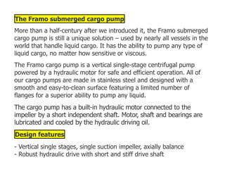
1. The Framo submerged cargo pump
More than a half-century after we introduced it, the Framo submerged
cargo pump is still a unique solution – used by nearly all vessels in the
world that handle liquid cargo. It has the ability to pump any type of
liquid cargo, no matter how sensitive or viscous.
The Framo cargo pump is a vertical single-stage centrifugal pump
powered by a hydraulic motor for safe and efficient operation. All of
our cargo pumps are made in stainless steel and designed with a
smooth and easy-to-clean surface featuring a limited number of
flanges for a superior ability to pump any liquid.
The cargo pump has a built-in hydraulic motor connected to the
impeller by a short independent shaft. Motor, shaft and bearings are
lubricated and cooled by the hydraulic driving oil.
Design features
- Vertical single stages, single suction impeller, axially balance
- Robust hydraulic drive with short and stiff drive shaft
2. -Fail-safe design; lubrication and cooling of pump by the hydraulic
driving oil medium.
- Pump material stainless steel
- Concentric hydraulic pipes for maximum safety
- Cofferdam, ventilated to atmosphere, protecting the entire pump
- Mechanical seal against hydraulic oil
- Double lip seal against cargo, only exposed to static pressure
- Anti-rotation brake; loading through pump
- Smooth pump exterior; self draining and easy to clean
Performance
The Framo cargo pump is easy to operate. The hydraulic drive
provides for a remote and local stepless capacity control through the
Speed Torque Control (STC) valve on the pump's top plate. The cargo
pump can pump anything liquid, regardless of specific weight or
viscosity.
3. It is impossible to overload or to overspeed the pump. The STC valve
automatically regulates hydraulic oil pressure and flow to the hydraulic
motor according to the given discharge situation.
The pump design allows operation with a minimum of liquid in the
tank which saves time spent for drainage and tank cleaning. The
Framo cargo pump has a built-in efficient stripping system.
Condition based maintenance
Seal monitoring is performed from the cargo pump top plate by
purging the cofferdam.
Replacement of wear and tear parts is easily done from inside of the
tank without interfering with the hydraulic section.
4.
5.
6. Submerged ballast pumps
Installation of ballast pumps inside the double side ballast tanks in
combination with a submerged cargo pump in each cargo tank make
the pump room superfluous. This arrangement provides a safer ship
design and make more space available for carrying cargo. Submerged
ballast pumps have become the standard arrangement in modern
tankers and FPSOs.
7. Increase the cargo volume with submerged ballast pumps. Eliminate
the pump room. The Framo ballast pump has a fail safe design with
impeller always immersed in water.
Increased cargo volume
8. Normally installed inside two of the double side ballast tanks located
aft of the manifold area, one in each side. On oil tankers, a fuel-oil
tank can separate the engine room and cargo section.
• No pump room required
• Larger volume available for cargo
Submerged installation
The Framo submerged ballast pump is a centrifugal pump, designed
for installation inside the ballast tanks.
The pump unit is mounted inside the air separator and protected by a
cofferdam. A fail-safe design ensures that impeller will always be
immersed in water.
This is a compact design which saves space and makes the installation
easy. An air ejector is connected to the pumps suction side. Automatic
start and stop of the air ejector makes the pump self priming. The
pump is manufactured from stainless steel with seawater resistant
bronze impeller.
9. Design features
• Impeller always immersed in water
• Built-in self priming system
• Individual capacities of up to 3.000 m3/h
• Stepless capacity control
• Robust design with a short and rigid drive shaft
•Lubrication and cooling of motor and bearings by the hydraulic drive
oil
• Cofferdam between ballast water and hydraulic section
• Concentric hydraulic pipes for maximum safety
• Easy to install, operate and maintain
• Can be connected to any ballast water treatment system
10. THIS IS A LAYOUT OF STANDARD PIPELIES FOR FRAMO
PUMPS:- THE HIGH PRESSURE SUPPLY LINE LINES HAVE
11. SQUARE PIPE FLANGES WITH SPIGOT AND HIGH PRESSURE
‘O’ RINGS, THE RETURN LINE HAS CIRCULAR FLANGES;
12.
13.
14.
15.
16.
17.
18. Components of FRAMO system
As with all centrifugal pumps, Framo pump also have
Impeller
Volute casing
But apart from being a centrifugal pump, FRAMO is also a submersible
pump. That is the pump is fitted inside the cargo tank and will be
submerged in the liquid (cargo).
Keeping this in mind, let us discuss the components of FRAMO system
to better understand this.
1. Hydraulic Motor
For the centrifugal pump to work, impeller need to rotate. But impeller
would not rotate on its own. It need a source of energy (prime
mover).
19. In steam turbine centrifugal pumps, this energy is provided by steam.
For electric pumps, electric motor provides this energy for rotating the
impeller.
In FRAMO system, this energy is provided by the Hydraulic motor
using the pressurised hydraulic oil.
How ? Well we all have read the below law of conservation of energy.
Haven’t we ?
“Energy can neither be created not destroyed. It can only be
converted from one form to another”
Hydraulic motor converts pressure energy of high hydraulic oil
pressure to rotational energy to rotate the impeller.
Below diagram is the most basic diagram that shows how a hydraulic
motor works.
High pressure oil enters the motor. It rotates the shaft and low
pressure oil leaves the motor.
20. In Framo system, you will not be able to see the hydraulic motor as it
is placed in the outer casing.
And there are no serviceable parts in a Framo hydraulic motor.
2. Power Packs
For the Hydraulic motor to rotate the impeller, there need to be high
pressure of hydraulic oil.
Power packs supply this high pressure hydraulic oil to the Framo
hydraulic motor.
Power packs are either installed in the forecastle store or in the engine
room of the ship.
Power pack system consists of
A hydraulic oil tank to draw the oil from
High pressure pump to take suction from the Hydraulic tanks and
pump this oil into the hydraulic pipeline on deck
21. Electric motor to run the High pressure pump
It is important that hydraulic oil tank always have sufficient oil for the
high pressure pump. If it has less or no oil, the pump will get
damaged.
Less or no oil can be because of two reasons.
No oil in the tank
Closed Suction valve to the power pack
There are two safe gaurds in the Framo system to ensure this.
“Closed suction line” trip
“Low oil level” trip
Closed suction valve trip
If the suction valve for the high pressure pump is closed, the power
pack will trip. This ensures that the suction valve of the pump to take
suction from hydraulic tank is not inadvertently closed.
22. The alarm for the trip will display in cargo control room as well as
Engine control room.
There is a sensor arrangement for the suction valve, which senses if
the suction valve is fully open.
In old Framo system this could be a manual valve with its handle
touching the sensor. If the suction valve is even slightly closed, its
looses the touch of sensor and trip is activated.
In new systems, the valve is not a manual valves. In this case the a
proximity sensor is fitted on top of the valve, that senses if the valve is
fully open or not.
Low oil level trip
The power pack can loose suction if there isn’t sufficient oil in the
hydraulic tank. For this reason when the oil level in the hydraulic tank
goes below minimum level, the power pack will trip.
23. The oil level in the hydraulic tank is kept just above the alarm level.
This ensures that any leakage in the line will be immediately detected
without the loss of much of hydrualic oil.
There are two alarms for low level
Low Level alarms, and
Low Low level Alarm
When the level is at Low level, an alarm will activate and will be
displayed in CCR and ECR.
If the level of the oil further drops to “Low Low”, the hydraulic oil
system (Power pack) will trip.
If the low oil level trip is activated, the reason for low level must be
investigated. The oil can then be refilled either from the standby tank
or spare drums whichever available.
It is important to fill only the correct grade of hydraulic oil.
3. Cofferdam and Purging routine
24. So far we have discussed that Framo pump is run by hydraulic motor
and Hydraulic motor gets the pressurised hydraulic oil from the power
packs
Now let us see the internal parts of the framo pump.
If you notice, the red section is the high pressure hydraulic oil going
into the hydraulic motor. Yellow part is the hydraulic oil return. Both
these pipes are concentric to each other. Like in below picture.
This pump is inside the cargo tank and there are two liquids (hydraulic
oil and cargo) that should not come in contact.
If the hydraulic oil leak into the cargo, cargo can damage. If cargo
goes into the hydraulic oil, the hydraulic system will damage.
As you might have guessed, there is something in the Framo pump to
prevent that. There is hydraulic seal that prevents hydraulic oil
leakage to the cargo side. And there is cargo seal that prevents cargo
leaking into the hydraulic side.
25. But seals can leak overtime, right ? so if any of these seals are leaking,
how would we know ?
That is exactly the purpose of cofferdam.
You can think of cofferdam as a steel cup with cargo seal at the
bottom. Any hydraulic oil or cargo leakage will collect in this
cofferdam.
It is important to know if the cofferdam is empty or not. And this is
done by purging the cofferdam.
We introduce air or nitrogen in the cofferdam and check the outlet of
the purging line.
If we just get the air in outlet of purging line, the cofferdam is empty.
So no leakage of hydraulic oil or cargo and both the seals are intact.
If we get cargo in the cofferdam, it indicates that the cargo seal of the
Framo pump is leaking
26. If we get Hydraulic oil in the cofferdam, it indicates that Hydraulic oil
seal of the framo pump is leaking
If we get mixture of Hydraulic oil and cargo, it indicates that both oil
seal and cargo seal are leaking
If any of the seal is leaking, it need to be replaced with new seal after
the discharging and tank cleaning of the tank.
Framo has a purging routine which shows when the purging of the
pump cofferdam need to be carried out.
27.
28.
29.
30. We must keep history of purging records for all previous voyages.
For some cargoes, we are supposed to not do the cofferdam purging.
These may be toxic cargoes such Toluene Diisocynate or solidifying
cargoes such as Palm oil.
In these cases we need to fill the cofferdam with some liquid (DOP in
case of loading TDI) so that cofferdam is not blocked with the cargo.
4. STC Valve (Before known as “Flow control valve)
Now we have the pump and the hydraulic system to run the pump.
But like any other type of cargo pump, Framo too would have an
operational requirement.
To be able to run the pump at different speeds
To achieve this, we should be able to control the flow of the hydraulic
oil to the hydraulic motor of the Framo pump. This is because more
the flow of pressurised oil to the hydraulic motor, more speed the
impeller will rotate.
31. This is exactly what Speed torque controller does. STC is fitted on top
plate of the pump on main deck. The Hydraulic oil inlet pass through
the STC.
STC of the pump controls the speed of the pump by allowing only the
required amount of hydraulic oil to pass through to the hydraulic
motor.
STC also prevent the pump to overspeed by controlling the amount of
oil to the hydraulic motor of the pump.
There are two ways to control the speed of the pump through STC.
From the local control on the STC
From the cargo control room
Local control valve on STC
32. With local control valve, we can control the speed of the pump locally
from the pump itself. This becomes handy during stripping of the
tanks or tank cleaning.
Local control valve is a kind of knob located on the STC. When we
close the knob (by turning clockwise), the STC passes the oil to the
pump.
When we open the knob (by turning anti clockwise), the STC bypasses
all the oil and nothing goes into the hydraulic motor. Pump stops or do
not run in this case.
By partially closing the local control valve, we can adjust the speed of
the pump.
Starting the pump from the cargo control room
Speed of the pump (or we can say operation of STC) can also be
controlled from cargo control room.
33. We do this by a lever provided in the cargo control room. Each pump
has a lever that connects with the STC of that pump by a hydraulic
control line.
34.
35. As we push the lever up to start the pump, a signal in form of
hydraulic control line pressure goes to the STC.
STC then releases the amount of oil to the hydraulic motor which will
be corresponding to the amount to lever lifted.
Here is the actual photo of the STC and pump stack on deck.
Remote start and Local start
Both, the remote start from CCR and local start from the pump
location are interconnected.
We cannot start the pump from local control if the pump Lever is not
pushed up from the CCR.
Same goes other way around.
If the local control knob is in open position, the pump will not work
even when the pump lever is operated from CCR.
So for the pump to operate, STC need to have the signal from both
from local control valve as well as remote lever in CCR.
36. If we need to start the pump from local control
We open the local control valve by rotating it anti clockwise
We push the lever up from the CCR
We operate the pump locally by slowly closing the local control valve
If we have to start the pump from CCR
We close the local control valve by rotating it clock wise
From CCR , we push the lever up to start the pump
5. Feed Pumps
For the Framo system to work efficiently, the hydraulic oil used in the
system need to be in absolute good condition.
There are few things that can degrade the hydraulic oil quality.
Moisture ingress due to hydraulic lines being in vacuum due to
temperature variation
37. Air in the system that can cause vibrations, frothing of the oil etc.
Small particles that can be inside the oil during filling of hydraulic oil
tank or after a maintenance on the system
Feed pump takes care of all of these issues. Here is how.
Feed pump always keep on running, 365 days in a year, 24 hours a
day. Feed pump maintains positive pressure in the lines and hydraulic
system . It continuously recirculate the oil through entire hydraulic oil
system
Usually pressure of more than 5 Bars is maintained in the system even
when the system is not in use.
Now when the system is always under positive pressure, the chances
of moisture ingress are minimum
Air if any is auto released to the Hydraulic tank while recirculation. Off
course if air is still suspected in the system, there is air purging
arrangements in the Framo.
38. And any particles in the system are filtered while feed pump runs the
hydraulic oil in recirculation mode. This is because the recirculated oil
is made to pass through the filter.
Recirculation of hydraulic oil through feed pump also avoids oil
temperature variations at different parts of the hydraulic system.
There is another function that feed pump serves.
It helps in keeping the feed pressure on the suction side of the main
hydraulic pump. This means that when high pressure power pack
pumps are taking suction from the hydraulic tank, feed pump ensures
that there is no negative pressure on the suction side.
Feed pump alarms
One of the feed pumps must always be running when the power packs
are not in operation. If the feed pump stops, the “protection
pressure Low” alarms will be initiated.
When starting the first main power pack, two feed pumps will
automatically start before the power pack is started. This is called high
39. capacity mode of feed system. This is to keep the feed pressure on the
suction side of the main hydraulic pump.
Now let us say that one of the feed pump stops while running in high
capacity mode and the power packs are running. In this case the third
feed pump will start automatically.
If running signal for the third feed pump is not obtained within 3
seconds, the “feed pressure low” alarm will be initiated and power
packs will shut down.
40.
41.
42. 6. Cooling and heating system
Hydraulic oil used in any hydraulic system has a optimum temperature
range for use. This is because higher temperature can damage the
seals and other components and also it accelerates the degradation of
oil.
Hydraulic oil used in Framo system is no exception.
Depending upon the surrounding temperature, the hydraulic oil used
in Framo may be below or above this temperature range.
If it is above the optimum range, the oil will need cooling. If it is below
the optimum range, it would need heating.
Even if the surrounding tempertaure is within optimum range, the oil
temperature will increase during operation.
If the surrounding temperature is below 20 C, we need to open the
heating and venting valve for heating with one power pack running.
When the oil temperature is well within operating range, other power
packs can be started.
43. Same goes for when the surrounding temperature is higher. The
hydraulic oil is made to pass through a oil cooler to cool the oil before
delivery on deck.
The cooling water inlet valve is automatically controlled. It will open at
hydraulic oil temperature above 50 C and will close when temperature
decreases to below 30 C.
The “high oil temperature alarm will activate if the oil temperature is
above 60 C.
44.
45.
46. When oil temperature reaches 70 C, the power packs will trip.
7. Emergency Stops
One final thing (among many other) that the operator of the Framo
pumps need to know is about “Emergency stops” for the pumps.
These are the push buttons installed at different locations. When
pressed, the hydraulic system will trip immidiately.
47. The common locations for these emergency stops are
Cargo control room
Manifold port side
Manifold starboard side
48. At the power pack location
On each ship, there could be few locations for emergency stop for
Hydraulic system. We must know all of these locations.
Conclusion
Submersible pumps on board tankers is the first choice for the ship
owners because of various advantages these offer.
This is particularly the case with chemical and product MR and LR
tankers.
Framo is leader among the submersible pumps fitted on board
tankers. For anyone working on tankers, this makes the thorough
knowledge of the Framo system a necessity.
49.
50.
51.
52.
53.
54. A one-pump-per-hold system
that is easy to operate and to
clean has been specially
designed for combination
vessels that are alternating
between wet and dry
cargoes. The cargo pumps
are installed in protective
enclosed corrugations
between the holds. Cargo
piping and cargo heaters are located on deck. Installation The OBO
cargo pump is installed in a closed corrugation at the aft end of each
cargo hold. Only the volute casing of the pump is submerged in cargo
inside a suction well, with a free-flow duct connection to the cargo
hold. The upper part of the pump-head and the complete pipe-stack
remain dry within the corrugation, which may be regarded as a
standard cofferdam.
55.
56.
57. FRAMO HYDRAULIC LINE CONTROL VALVES:- ACCESSORIES
We will discuss the following basics components of FRAMO
system on board 1. Speed Torque controller 2. Pump Remote
control system 3. Heating and Venting 4. Oil Filling Procedure.
1. FRAMO Speed Torque Controllers (STC)
These are divided in two groups: 1. STC integrated on a pump top
plate, ref. fig. 1. 2 . STC separately mounted valves, ref. fig. 2.
60. In below pic you can see STC main parts
Pilot oil usually externally through pilot connection X (orifice A
plugged). For most FRAMO Speed Torque Controllers integrated on
61. top plate, equipment for purging of the cofferdam are built into the
valve
For all valves delivered after January 2002, a last chance filter
(strainer) is included in pilo tconnection, to reduce possibility of valve
failure due to particles.
2. OPERATING INFORMATION
FRAMO Speed Torque Controller, STC, is designed to control
the discharge from centrifugal pumps powered by a common
ring main hydraulic system.
The valve has three main functions, ref. fig. 4:
1. Torque Control (TC).
The valve is used to control the torque of the hydraulic motor
independent of inlet pressure (P1). The local control valve with hand
wheel regulates the pilot pressure and thereby the inlet pressure to
the motor (P2). This can also be done by means of a remote control
valve.
62. 2. MaximumSpeed Control (max. SC).
The valve limits the oil flow to the hydraulic motor. This
function overrides the TC function. This can be observed during
certain discharge situations: Any attempt to Increase motor inlet
pressure P2 by turning the local, or remote, control valve
against maximum position, or by increasing inlet pressure P1,
will be ignored by the STC valve.
Some valves are delivered with an adjustable compensator. By using
this valve, maximum speed can be reduced to approx. 65 % of
specified maximum speed. Maximum speed setting can only be
regulated locally. Turn CCW to reduce maximum speed. Turn CW until
hand-wheel stops, to adjust back to specified maximum speed.
The adjustable compensator is used to reduce maximum speed during
stripping, tank cleaning and other pump operations where maximum
speed/maximum discharge head is not required.
63. 3. Closing.
The valve will close off the oil flow when the difference between pilot
pressure and return pressure is below appr. 10 bar.
Venting of the valve
Any air pockets remaining inside the valve may cause malfunction.
Vent by slightly unscrewing the two venting plugs, at minimum system
64. pressure. A flexible hose with inner diameter 7 mm to be connected as
shown, to prevent oil spill.
The local control valve
(pressure relief) also
needs to be vented. There
is a separate venting plug
for this purpose. Return side
of hydraulic system should
be pressurized during
venting (Feed pumps
running). Venting of the
local control valve is only to be carried out when the valve is
completely relieved.
2. Pump Remote Control:- A standard system consists of minimum 2
manifolds. See figure BELOW. Each manifold includes a pilot line
filter and service valves (isolating valve on filter inlet, and
65. check valve on manifold outlet). There may be up to 14 valves
on each manifold.
68. A command given by operator (0-10V), corresponds to a required
pressure 0-300 bar. The command signal is converted to a solenoid
current, driving the proportional solenoid against a spring. At zero
command the solenoid force is zero and the spring drives the spool in
the fail-safe position, resulting in pilot pressure equal to return
pressure.
Increased command gives higher solenoid force and hence pilot
pressure. The actual pilot pressure is measured by a pressure
tranducer. Its output signal gives both a feedback signal to the
operator about actual pressure, and it gives feedback to the valve
regulator. If there is a difference between pressure command signal
and feedback signal, the internal pressure controller changes the
current until difference is minimized (+/- 6 bar accuracy).
The Pump Control valve may be equipped for both local and remote
control. It is required that when using the remote control (RCV) the
local control valve must be set in maximum position & vice versa. The
command signal to the valve is usually set by a control potmeter at
Framo Control Panel Before air venting set the command
69. (potmeter) for all RCV on the Framo Control Panel to half position.
Start power pack and run at minimum system pressure (approx.70
bar).
Air bleed main bores in manifold, P and R, by connecting a test hose
to P and R bleed test connections. Ref. figure below. Then bleed on
connections A on each valve the same way. Finally, air bleed valve
internals by opening air venting screw on valve. Slowly open the
venting screw about one turn and wait until the oil is free of air
bubbles. Then close air venting screw.
70. 2.2 Normal operation from control panel:
The pump is normally operated from Framo Control Panel in cargo
control room. The control panel includes one control potmeter and one
monitoring indicator for each pump. Pump starts when potmeter for
actual pump is pushed forward. Achieved pilot pressure to pump
control valve can be read at monitoring indicator (pilot pressure is
measured on pressure control manifold).
71. Note: When pump is in maximum speed control, pilot oil flows from
remote control valve to STC
valve, and measured pilot pressure may differ from actual pilot
pressure on STC valve, because of pressure drop in pilot line.
2.3 Manual pressure override:
In case of electrical failure you can mechanically connect the port P to
port A, and run the cargo pump by the local control valve. Remember
to unload local control valve before changing to manual override.
Loosen the lock nut at the end of the valve (see fig. 7), and screw the
hexagon socket set screw clockwise.
After manual operation is finished, connect port A to port R by
screwing counter-clockwise. DO NOT USE FORCE ON THE SCREW FOR
MANUAL OVERRIDE. Fasten the lock nut.
76. 4. Oil filling of hydraulic piping system
If the HPU (Hydraulic Power Unit) is located aft, the ship should
preferably have aft trim during oil filling and venting and forward trim
if it is located forward. Note! Always fill oil by pumping into the lowest
part of the system to avoid mixing with air.
Venting must be done from all the high points in components and
pipes, both on pressure- and return side. If deck machinery is
connected to the system, these are normally at the highest level.
Avoid oil spill during venting by using a flexible hose with 7 mm inner
diameter on the venting Plug, and collect the oil in a suitable bucket.
Use the following filling procedure):
1.Check storage tank oil level and drain off a small quantity of oil for
visual check.
2.Close heating and venting valve, and open all venting plugs on the
pressure side highest points. 3. Connect hydraulic oil transfer unit for
filling from T and into HP (high pressure) line, and start the pump. 4.
77. Vent on all highest points until the pressure side is completely filled
with oil, then stop the transfer pump. 5. Open all venting plugs on the
return side highest points. 6. Change for filling from T and into LP (low
pressure) and start transfer pump.
7.Vent on all highest points including main return filter until the return
side is completely filled with oil. Stop transfer pump at normal system
tank level.
8.Connect transfer unit for circulation from C to HP. Open heating and
venting valve, and start transfer pump. 9. Circulate the oil and vent
until the piping system seems to be completely free from air.
10. Stop transfer pump and let the oil settle for at least 12 hours, then
restart for circulation and venting. 11. When the system is completely
free from air, stop transfer pump, close valves and disconnect flexible
hoses.
Note! The valves for oil transfer must always be closed, and flexible
hoses disconnected after use.
80. 2. Close the pressure service valve in front of the pump
control valve (STC
valve).
3. Open the STC local control valve completely.
4. Put the remote control handle (on
the panel) in max. position.
5. Open the pressure service valve in front of the pump
remote control assy.
6.Start one power pack and set the system pressure to 70-
100 bar.
7. Vent the pump remote control assy. through the test
connections and the
venting plugs until it is completely filled with oil.
8. Open the service valve on the pilot outlet from pump
remote control assy.
81. 9.Open the vent plug on the pump’s return service valve (for
venting of the
return side).
10.Vent the STC valve local control valve (must always be
open when venting) and the valve cover until the valve and its
pilot line is completely filled with oil..
82. Gas carriers have specific cargo containment and handling
requirements due to the highly volatile nature of their cargo. In the
event that flammable gases are ignited, extinguishing solutions that
83. can be deployed quickly and effectively whilst minimising the risk to
personnel and the environment is required.
Dry Chemical powder: The Dry Chemical is a powder composed of
very small particles, usually of sodium bicarbonate, potassium
bicarbonate, potassium sulphates, urea-potassium based bicarbonate,
potassium chloride, or mono ammonium phosphate with added
particulate material supplemented by special treatment to provide
resistance to packing, resistance to moisture absorption (caking), and
the proper flow capabilities
Dry Power Content on ship: Potassium Sulphate
What is an expellant?
It is an inert gas that provides the internal pressure in a fire
extinguisher to expel the extinguishing medium e.g. Dry chemical
powder, water, foam. The expellant for a stored pressure (STP) fire
extinguisher is the gas inside the unit that pressurises the
extinguisher. The expellant gas pressure is recorded on the STP units
gauge. The cartridge operated type fire extinguisher has the expellant
84. gas inside a cartridge which is released manually into the extinguisher
when pressure is required to expel the extinguishing medium.
Why Nitrogen is used as Expellant?
Nitrogen (N2) is extensively used for pressuring STP fire
extinguishers as it is a dry gas and will not contaminate a dry
powder extinguishing medium.
It is also the cheapest of all the acceptable gases
Max water content is less 0.006 m/m
N2 is transported in very high pressure cylinders (200
Bar)20000Kpaand a pressure
reducing Regulator must be used to pressurise an STP fire
extinguisher to its
specified Internal pressure (normally 14Bars) 1400Kpa
Why Co2 not used as Expellant?
CO2 is a wet gas and Dry Chemical Powder (DCP) is hydroscopic
(attracts moisture), this causes the DCP to go lumpy or hard. An STP,
DCP fire Extinguisher will then fail to operate successfully.
85. Advantages of DCP Extinguisher
Breaks down the chemical reaction within the fire and suppresses
the flames almost immediately.
system is an effective
non-toxic alternative which is harmless to people and the
environment
Powder penetrates into the smallest and even partially covered
locations
Can be operable at low temperatures also
General system principles
The powder is stored in a pressure tank and is discharged by using a
propelling gas, normally nitrogen & other gases can also be used.
Separately stored propellant the principle most frequently used in fixed
and larger mobile systems is to have the propellant (normally
Nitrogen) stored in separate tanks. The powder is stored in a tank at
atmospheric pressure and pressurised when the system is activated.
86. Pressurizing through a pressure regulator is the normal principle for
fixed installations and the basis for the systems further described here.
This method gives the best control of the discharge and ensures a
steady discharge rate through the whole discharge period.
Endothermic reaction of the dry chemical’s main component (usually a
bicarbonate of sodium, potassium or other salt) that causes absorption
of heat and, consequently, favours extinction; production of carbon
dioxide, consequent to the scission of the extinguishing dry chemical,
that reduces the quantity of oxygen involved in combustion and
formation, in some cases, of water vapour that once more reduce
oxygen, When projected onto fire, extinguishing dry chemicals actually
interfere with the combustion chain reactions to hinder their
propagation: the larger the surface area on contact between flames
and a dry chemical, i.e. the smaller the powder particles, the more
effective is the dry chemical itself as a fire extinguishing agent. When
the above-indicated phenomena occur and free radicals are reduced,
there is corresponding progressive decrease of the combustion
reaction; the whole process culminates in complete extinction.
87. IGC Code 2016 Regulation:
1.Ships in which the carriage of flammable products is intended shall
be fitted with fixed dry chemical powder fire-extinguishing systems,
approved by the Administration based on the guidelines developed
by the Organization, for the purpose of fire fighting on the deck in
the cargo area, including any cargo liquid and vapour discharge and
loading connections on deck and bow or stern cargo handling areas,
as applicable.
2.The system shall be capable of delivering powder from at least two
hand hose lines, or a combination of monitor/hand hose lines, to any
part of the exposed cargo liquid and vapour piping, load/unload
connection and exposed gas process units.
3.The dry chemical powder fire-extinguishing system shall be
designed with not less than two independent units. Any part required
to be protected by 11.4.2 shall be capable of being reached from not
less than two independent units with associated controls, pressurizing
medium fixed piping, monitors or hand hose lines. For ships with a
88. cargo capacity of less than 1,000 m3, only one such unit need be
fitted. A monitor shall be arranged to protect any load/unload
connection area and be capable of actuation and discharge both locally
and remotely. The monitor is not required to be remotely aimed, if it
can deliver the necessary powder to all required areas of coverage
from a single position. One hose line shall be provided at both port-
and starboard side at the end of the cargo area facing the
accommodation and readily available from the accommodation.
11.4.4 The capacity of a monitor shall be not less than 10 kg/s. Hand
hose lines shall be non-kinkable and be fitted with a nozzle capable of
on/off operation and discharge at a rate not less than 3.5 kg/s. The
maximum discharge rate shall allow operation by one man.
The length of a hand hose line shall not exceed 33 m. Where fixed
piping is provided between the powder container and a hand hose line
or monitor, the length of piping shall not exceed that length which is
capable of maintaining the powder in a fluidized state during sustained
or intermittent use, and which can be purged of powder when the
system is shut down. Hand hose lines and nozzles shall be of weather-
89. resistant construction or stored in weather resistant housing or covers
and be readily accessible.
Maintenance Guidelines: MSC.1/Circ.1432
Monthly testing and inspections
5.6 Fixed dry chemical powder systems
Verify all control and section valves are in the proper open or closed
position, and all pressure gauges are in the proper range.
Annual testing and inspections
7.9 Fixed dry chemical powder systems
1 visually inspect all accessible components for proper condition;
2verify the pressure regulators are in proper order and within
calibration; and
3agitate the dry chemical powder charge with nitrogen in accordance
with system manufacturer’s instructions.
90. (Note: Due to the powder’s affinity for moisture, any nitrogen gas
introduced for agitation must be moisture free.)
Two-year testing and inspections
8.2 Fixed dry chemical powder systems
1blow dry nitrogen through the discharge piping to confirm that the
pipe work and nozzles are clear of any obstructions;
2 operationally test local and remote controls and section valves;
3verify the contents of propellant gas cylinders (including remote
operating stations);
4 test a sample of dry chemical powder for moisture content; and
5subject the powder containment vessel, safety valve and discharge
hoses to a full working pressure test.
Ten-year service
10.3 Fixed dry chemical powder systems
91. Subject all powder containment vessels to hydrostatic or non-
destructive testing carried out by an accredited service agent.
8 Most Common Problems in Hydraulic Operated Remote
Valve System on Ships
A cargo ship has a variety of machinery types, which are connected to
different piping systems that supply essential oil and water for efficient
operation. In tanker ship, the cargo tanks are connected to the pipes,
which are used for loading and unloading of cargo.
The important piping system of the ship, such as ballast water system,
cargo piping system, bunker piping etc. are provided with hydraulic
operated valves to restrict and control the flow of oil/water/cargo
through the pipes in a simple, safe and economical way.
The hydraulic operated valves system consists of the following
essential parts:
1. Hydraulic Power Pack:
92. The hydraulic power unit is a combined system which supplies,
operates and controls the flow of oil to the hydraulic valves when an
open or close signal is given from the engine control room or the
cargo control room. It consists of the following components:
i. Signal receiver
ii. Hydraulic tank
iii. Pumps
iv. Level gauges
v. Pressure gauges
vi. Alarms
vii. Filters
93. The power pack will operate the pumps depending on the line
pressure and acknowledge the command given from the ECR or CCR
to open or shut the valve (Start and Stop Pressure).
2. Pumps
94. The other important part of the hydraulic operating system are the
two pumps fitted with the hydraulic power pack unit. Here, one acts as
main and other as a standby pump, with each having a capacity to
open or close valves simultaneously in one minute.
Related Read: Types of pumps used on ships
3. Accumulators
Accumulators are pressure storing devices, which are a part of the
hydraulic power pack. The capacity of the accumulator should be
sufficient to compensate the oil leakage in the hydraulic supply piping
system for at least five minutes and supplying oil to operate minimum
three largest hydraulic valves in the system to change from shut to
open position or vice versa.
4. Actuator:
A valve actuator is an assembly of piston and cylinder which operates
the valve at the local position. It receives the oil from the hydraulic
power pack for operating the valve.
95. The most common problem found in a ship’s hydraulic operated
remote valve system are:
1. The hydraulic supply pump is not starting:
96. The hydraulic supply pump is the primary source of control for the
remote control valves. In case of any problem with one pump, the
standby pump must be started to resume the operation, if needed
immediately. Following are the indication the set supply pump is not
starting:
– No running indication lamp light
– Low oil pressure alarm active
– Low oil level alarm active
Related Read: 10 Practical Tips To Handle Engine Room Pumps
Following are the causes of the pump not working:
a. Electrical problem:
Low Voltage
Disconnection of wire
A problem in electric motor
b. Pump problem:
97. Blocked motor
Blocked pump
c. Oil problem:
Leakage of oil
Wrong setting of oil level switch
Troubleshooting the above causes:
a. Electrical problem
Check presence of voltage
Check control place for wire connections
Check motor intensity and winding
Related Read: How to find earth fault on board ships?
b. Pump problem:
Change to stand by pump
Check motor or pump for free revolution
Overhaul motor or pump is necessary
98. c. Oil Problem:
Check oil level
Check and rectify leakage
Ensure tank level is appropriate
Re-set the oil level switch
Clogged inlet filter (if provided)
2.Clogged Circuit: In case of a
clogged circuit, the oil supplied by
the correctly operated pump will not
reach the valve and hamper the
remote operation. Following are the
most common causes of a clogged
circuit:
a. Impurities:
Use of low-grade oil
99. Improper cleaning after overhauling
Related Read: Important lube oil qualities to consider while choosing
lube oil on ships
b. Foreign substance:
Access to foreign material during repairs
Access to external substance during oil filling
c. Inefficient Flushing operation
d. Burst filter cartridge
Troubleshooting the above causes:
a. Impurities:
–Inspection of the whole installation to find a reason for impurity
access
– Use good quality of hydraulic oil as prescribed by the maker
– Ensure to clean the system properly after overhauling
100. b. Foreign substance:
– Ensure to clean the system properly after repairing
– Inspect the tank after cleaning for left out rags/clothes
c. Flushing:
– Flush the whole installation
d. Burst or clogged filter:
– Clean the filter
– Change the filter cartridge
3. Unusual Noise from Pump:
A working pump has a usual noise when running. An engineer officer
should know how the regular operating machine (including pumps)
sounds. Following are the most common causes of unusual pump
sound:
101. a. air ingress at the suction of the pump
b. damage pump parts
c. defective motor-pump coupling
Troubleshooting the above causes:
a. Air ingress:
– Check the tightness of the pump suction circuit
– Purge the air from the circuit
b. Damage pump parts:
– Switch to st. by pump
– Overhaul the affected pump
– Change the bearing
c. Defective motor-pump coupling
– Check the coupling for damage
– Check the tightness of coupling bolts
102. – Check the motor- pump coupling shaft alignment
– Replace coupling, if required
Related Read: 7 Common Problems Found in Pumps On Board Ships
4. Slow valve movement:
Once the signal is given to operate a hydraulic valve from ECR or CCR;
the valve should fully open or shut in a given time. A delay in the
operating timing of the valve is caused by:
a. Defective control valve operation
b. Clogged flow reducer
c. Clogged filters
d. Low oil pressure
e. Low oil temperature
f. Damaged valve actuator
Troubleshooting the above causes:
a. Check control valve operation
b. Check flow reducer adjustment
103. c. Clean the clogged flow reducer
d. Clean the clogged filter
e. Check and maintain oil pressure
f. Check and maintain oil temperature
g. Preheat the oil in cold weather
h. Check actuator operation
i. Check valve torque
Related Room: The basics of troubleshooting engine room machinery
5. Jerking valve Operation:
The jerking of the hydraulic valve is not suitable for valve itself, and it
will also lead to improper valve operation, i.e. delay in opening/closing
and pressure surge in the system.
Jerk in the valve is caused by:
a. Pressure surge
b. Air in the system
104. c. Faulty accumulator
d. Faulty actuator
Troubleshooting the above causes:
a. Carry out air purging of the system
b. Maintain the pressure from the hydraulic power pack unit
c. Overhaul the faulty accumulator
d. Overhaul the faulty actuator
Related Reading: 12 Ways To Master Engine Room Watchkeeping
Procedure
6. Valve does not shut entirely:
A valve needs to shut fully as a partially closed valve may lead to
continue in the flow and result in spilling of the fluid. Following are the
most common causes of the valve not getting entirely shut:
a. Internal leakage of hydraulic actuator
b. Oil pressure too low
105. c. The problem in relief and check valve
d. The operation time of the valve is too slow
Troubleshooting the above causes:
a.Check the pressure on actuator after the operation, if the pressure
is decreased quickly, check the seal on the actuator and if required,
replace the seal with new ones.
b. Maintain the rated pressure in the hydraulic system
c.Check the operation of relief and check valve. Replace with a new
one if faulty
d.Check the operating time of the valve and adjust the same to the
recommended timing prescribed by the maker
7. Valve is not moving:
It may happen that a valve which is signalled from the CCR or ECR to
open or shut is not moving at all.
106. This may lead to a spill of fluid (if the valve is stuck in open position)
or over-pressurisation of the connected piping system (if the valve is
stuck in a closed position). No movement of the valve is caused by:
107. a. Problem in electric control system
– No/low voltage
– Disconnection of wires
– Problem in electrical parts – switches, solenoid valve etc.
b. Problem in hydraulic actuators, valves or pipes
– Coil of the solenoid damaged
– Leaking pipes
– Clogged flow reducer
– Spool of control valve or actuator piston jammed
– Foreign body in the valve circuit
– Damaged actuator
Troubleshooting the above causes:
a. Electric control system:
– Check presence of voltage on control circuit
– Check each cable terminal connection
– Check each electrical apparatus (i.e., switches, solenoid valves etc.)
108. b. Hydraulic Components:
– Check solenoid valve operation
– Check and adjust flow reducer
– Check hydraulic pipes for leakages
– Check actuator for correct operation
– Check oil pressure
8. Wrong valve position indication:
The main purpose of the hydraulic controlled valve is to operate it
remotely. The ECR and CCR control panel for such valves are provided
with position indicator showing the current position of the valve (Open
or Shut). If the indicator is showing a wrong position, it may lead to
confusion and operator may proceed not knowing the actual or real
position of the valve.
Following are the most common causes for the wrong position
indication:
109. a. Defective flow meter
b. Defective pressure switch.
c. Problem in indicator panel
Troubleshooting the above causes:
a. Overhaul the flowmeter
b. Check and rectify the fault with pressure switch
c. Check and rectify indicator panel problem
These are some of the most common problems which are encountered
on the hydraulic remote control valve system provided in ships.
However, the above list must not be considered as complete. The
engineer’s experience is an essential factor in fault finding and
troubleshooting.
Related Read: Can reverse engineering help marine engineers
troubleshoot engine room machinery on ships
All the ship personnel responsible for the operation of the hydraulic
controlled remote valve must know the location of all the valves
110. operated by the same. He/she should know how to open/shut them in
case the hydraulic system fails to operate.