Passive Air Cooling System and Solar Water Heater.ppt
Digital design slides for engineering
1. CIRCUITS
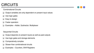
Combinational Circuits
❑ Output variables are only dependent on present input values
❑ Use logic gates
❑ Easy to design
❑ Faster operation
❑ Examples – Adder, Subtractor, Multiplexer
Sequential Circuits
❑ Output depends on present inputs as well as past outputs
❑ Use logic gates and storage elements
❑ Comparatively complex
❑ Slower than combinational circuits
❑ Examples – Counters, Shift Registers
2. SEQUENTIAL CIRCUITS
❑ Memory elements store binary information. This information at any given time determines the state of the circuit
at that present time.
❑ All electronic components have the ability to send, receive, store and process binary information. The
technology supporting these devices depends on electronic components that can store information i.e. have
memory.
❑ The binary information from external inputs along with the present state of the storage elements determines the
binary value of the outputs.
3. SYNCHRONOUS SEQUENTIAL CIRCUITS
❑ Circuit output changes only at some discrete instants of time.
❑ The circuit achieves synchronization by using a timing signal called CLOCK.
❑ A CLOCK generator provides a periodic train of pulses called the CLOCK signal.
❑ The storage elements are affected only by the arrival of CLOCK pulse.
4. ASYNCHRONOUS SEQUENTIAL CIRCUITS
❑ No CLOCK pulses. Changes take place whenever there is a change in inputs.
❑ More difficult to design in comparison to synchronous sequential circuits.
❑ Preferred when higher speed is required.
❑ These are basically combinational circuits with feedback loops.
5. STORAGE ELEMENTS: LATCHES
❑ Storage elements that operate with signal levels (and not signal transitions) are refereed to as latches.
- Level Sensitive Devices
SR Latch with NOR gates
9. LATCHES AND FLIP-FLOPS
❑ Latches are not suitable in synchronous logic circuits.
❑ The state transition in latches start as soon as CLOCK pulse rises to logic 1. The new state of latch appears at
the output while the pulse is still active. So, if the inputs applied to the latches change while the CLOCK pulse
is still high, a new output state may occur creating an unpredictable situation.
❑ The problem is solved by using a special timing control signal called a clock to restrict the times at which the
states of the memory elements may change, leading us to the edge-triggered memory elements called
flip-flops.
❑ Flip-flops are edge triggered devices.
10. EDGE TRIGGERED FLIP-FLOPS
❑ S-R, D and J-K edge-triggered flip-flops. Note the “>” symbol at the clock input.
Positive edge triggered flip-flops
S
C
R
Q
Q'
D
C
Q
Q'
J
C
K
Q
Q'
Negative edge triggered flip-flops
11. S-R FLIP-FLOP
❑ S-R flip-flop: on the triggering edge of the clock pulse,
❑ S=HIGH (and R=LOW) - SET state
❑ R=HIGH (and S=LOW) - RESET state
❑ both inputs LOW - no change
❑ both inputs HIGH - invalid
❑ Characteristic table of positive edge-triggered S-R flip-flop:
X = irrelevant (“don’t care”)
↑ = clock transition LOW to HIGH
13. EDGE TRIGGERED FLIP-FLOPS
❑ Flip-flops: synchronous bistable devices
❑ Output changes state at a specified point on a triggering input called the clock.
❑ Change state either at the positive edge (rising edge) or at the negative edge (falling edge) of the clock signal.
14. S-R FLIP-FLOP
Positive-going transition
(rising edge)
CLK
CLK'
CLK*
CLK'
CLK
CLK*
Negative-going transition
(falling edge)
CLK'
CLK
CLK*
CLK
CLK'
CLK*
❑ The pulse transition detector detects a rising (or falling) edge and produces a very short-duration spike.
15. D FLIP-FLOP
❑ D flip-flop: single input D (data)
- D=HIGH a SET state
- D=LOW a RESET state
❑ Q follows D at the clock edge.
❑ Convert S-R flip-flop into a D flip-flop: add an inverter.
S
C
R
Q
Q'
CLK
D
A positive edge-triggered D flip-flop
formed from an S-R flip-flop.
16. JK FLIP-FLOP
❑ Q and Q' are fed back to the pulse-steering NAND gates.
❑ No invalid state.
❑ Include a toggle state.
❑ J=HIGH (and K=LOW) - SET state
K=HIGH (and J=LOW) - RESET state
Both inputs LOW - no change
Both inputs HIGH - toggle
17. T FLIP-FLOP
❑ Formed from JK flip-flops by tying the J and K inputs together.
❑ No invalid state.
18. RACE AROUND CONDITION
❑ It is a phenomenon which occurs in level triggered JK flip flops when there is a 1 at both input terminals.
❑ Race around – continuous toggling
❑ If the width of the clock pulse is too long in comparison to propagation delay of the gates, the state of
flip-flop will keep on changing from 0 to 1, 1 to 0 and so on and the final state will be uncertain.
20. SOLUTIONS OF RACING
1. Clock pulse duration < Propagation delay of gates (Not feasible)
2. Edge triggered Flip Flops
3. Master- Slave Flip Flop
21. MASTER-SLAVE JK FLIP-FLOP
❑ It has two cascaded flip-flops with complemented clocks.
❑ Output of second flip-flop fed back to steering gates of first flip flop.
22. MASTER-SLAVE JK FLIP-FLOP OPERATION
❑ Assume that previous state of flip flop is 1 and 0.
❑ When Clock is 0, slave latch is enabled and its output is equal to master latch .
23. MASTER-SLAVE JK FLIP-FLOP OPERATION
❑ When Clock =1, master is enabled.
❑ Any change in J, K can only affect the output of the master.
24. MASTER-SLAVE JK FLIP-FLOP OPERATION
❑ When Clock =0 again, master is disabled and the current value of master is transferred to the output of
the slave.
26. CHARACTERISTIC EQUATIONS OF FLIP-FLOPS
❑ It expresses the next state of flip-flop in terms of present state and present inputs (excitations).
❑ Steps to obtain characteristic equation of flip-flops:
1. Write the characteristic table of the flip flop.
2. Draw a K-map for the next state of the flip-flop in terms of present state and inputs.
3. Find the characteristic equation using K-map.
35. FLIP-FLOPS CONVERSION
1. Identify available and target flip-flop type.
2. Write down characteristic table of target flip-flop.
3. Write down excitation table for available flip-flop.
4. Using K-maps, find the expressions for inputs of target flip flops.
5. Draw the circuit diagram.
36. SR TO JK FLIP-FLOP CONVERSION
Step 1 – Available flip flop – SR
Target flip flop - JK
Step 2 – Characteristic table of JK flip flop Step 3 – Excitation table of SR flip flop
37. SR TO JK FLIP-FLOP CONVERSION
Step 4 – Expressions using K-map
Combine both truth tables into one table
38. SR TO JK FLIP-FLOP CONVERSION
Step 5 – Circuit Diagram
39. D TO SR FLIP-FLOP CONVERSION
Step 1 – Available flip flop – D
Target flip flop - SR
Step 2 – Characteristic table of SR flip flop Step 3 – Excitation table of D flip flop
43. REGISTERS
❑ An n-bit register has a group of n flip-flops and some logic gates and is capable of storing n bits of information.
❑ The flip-flops store the information while the gates control when and how new information is transferred into
the register.
❑ Some functions of registers:
- retrieve data from register
- store/load new data into register (serial or parallel)
- shift the data within register (left or right)
❑ Example: A 4-bit register. A new 4-bit data is loaded every clock cycle.
44. REGISTERS WITH PARALLEL LOAD
❑ Instead of loading the register at every clock pulse, we may want to control when to load.
❑ Loading a register: transfer new information into the register. Requires a load control input.
❑ Parallel loading: all bits are loaded simultaneously.
45. SHIFT REGISTERS
❑ Another function of a register, besides storage, is to provide for data movements.
❑ Each stage (flip-flop) in a shift register represents one bit of storage, and the shifting capability of a register
permits the movement of data from stage to stage within the register, or into or out of the register upon
application of clock pulses.
Data in
Data out
(b) Serial in/shift left/serial out
Data in
Data out
(c) Parallel in/serial out Data out
Data in
(d) Serial in/parallel out Data out
Data in
(e) Parallel in /
parallel out
46. SERIAL IN/ SERIAL OUT SHIFT REGISTERS
❑ Accepts data serially – one bit at a time – and also produces output serially.
❑ One flip-flop for each bit to be handled.
❑ Usually, movement is only in a single direction. Each clock pulse shifts the contents of the register by one bit.
❑ Asynchronous preset and clear inputs are used to set initial values.
47. SERIAL IN/ SERIAL OUT SHIFT REGISTERS
❑ Data flow in SISO shift registers
50. SISO SHIFT REGISTERS APPLICATIONS
❑ SISO Shift Registers are used in data communication
- RS 232
- Modem transmission and reception
- Ethernet links
- SONET etc.
51. SERIAL IN PARALLEL OUT SHIFT REGISTERS
❑ Accepts data serially.
❑ Outputs of all stages are available simultaneously.
❑ We need a shift register of length N to convert N-bit word from serial to parallel.
❑ It would require N clock pulses to load data and one clock pulse to unload data.
❑ Applications - to convert data from serial format on a single wire to parallel format on multiple wires
(demultiplexing). E.g. - output data from a microprocessor to a remote panel indicator.
52. PARALLEL IN SERIAL OUT SHIFT REGISTERS
❑ Accepts data in parallel at all input pins.
❑ Data is read out sequentially from the registers one bit at a time.
❑ One clock pulse to LOAD and four clock pulses to UNLOAD.
❑ Application – read data into a microprocessor
53. PARALLEL IN PARALLEL OUT SHIFT REGISTERS
❑ Accepts data in parallel at all input pins.
❑ Data is read out in parallel from the registers.
❑ One clock pulse to LOAD and one clock pulse to UNLOAD.
❑ Application – temporary storage device or as time delay device