
Download as PDF, PPTX

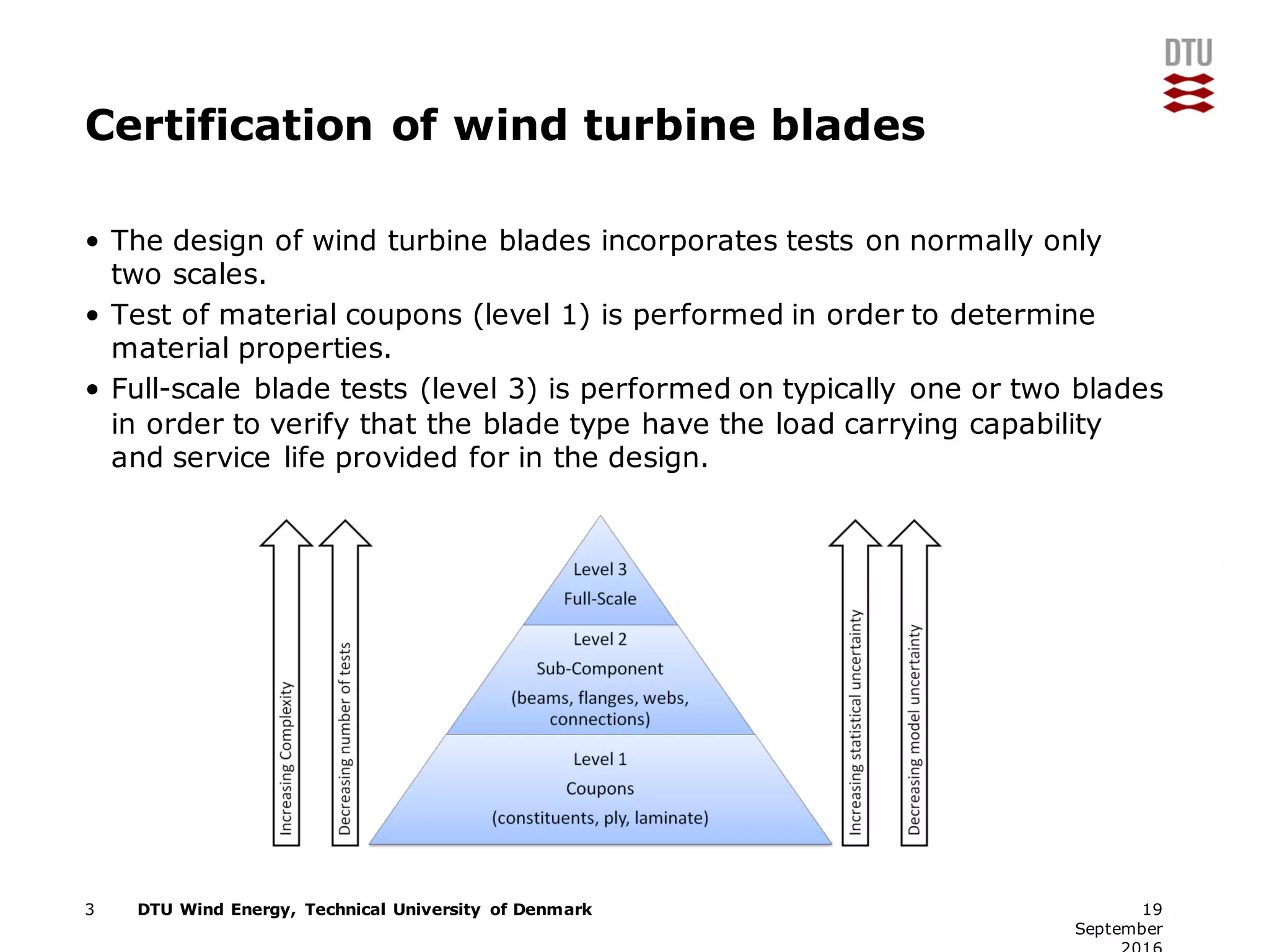
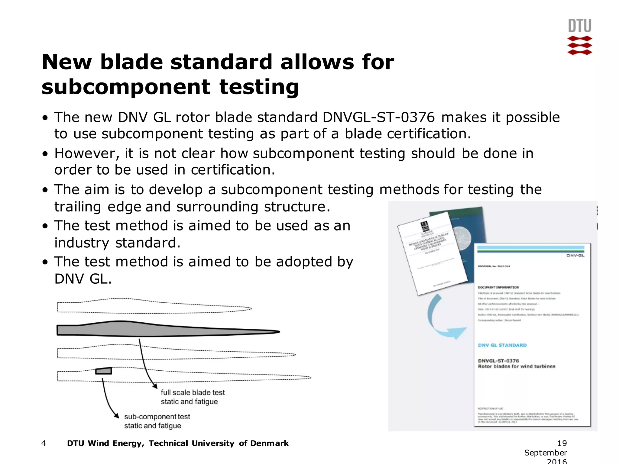
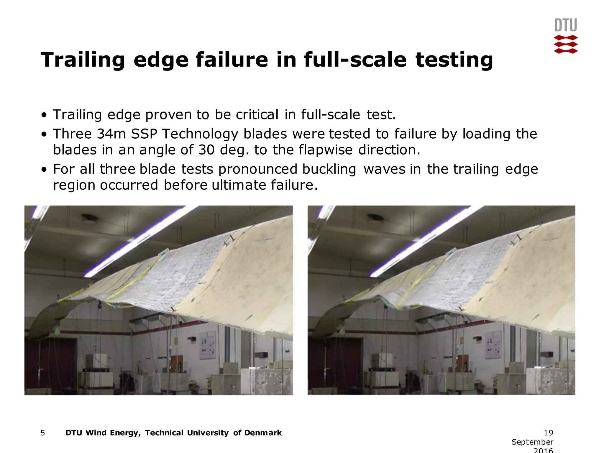
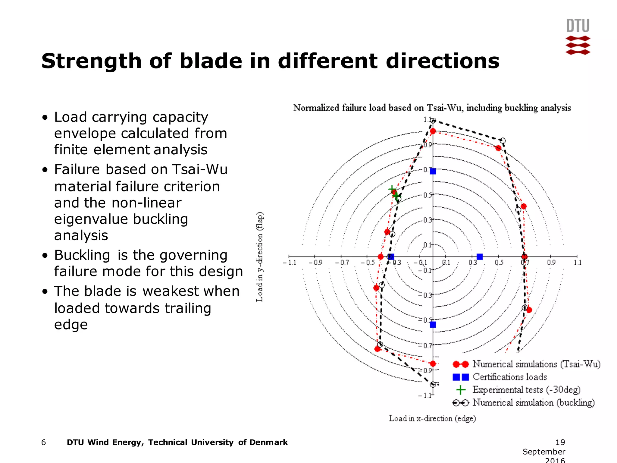
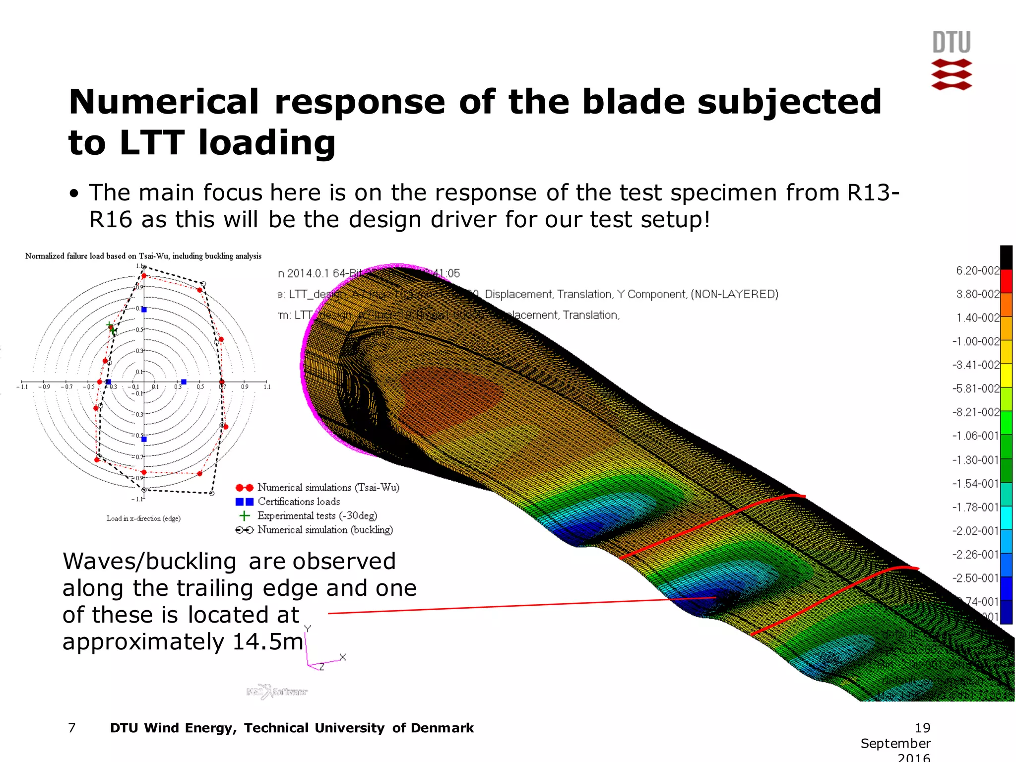
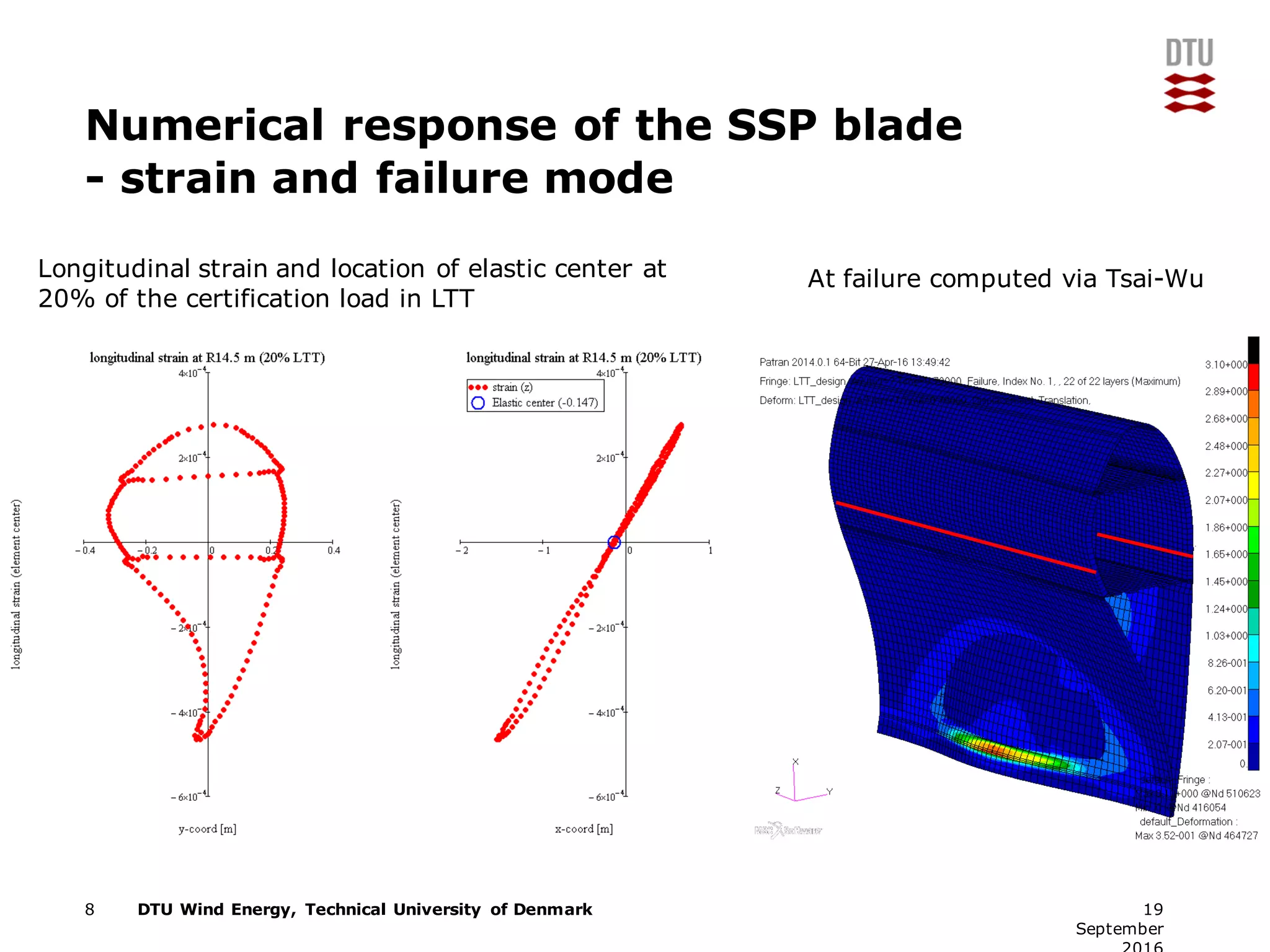
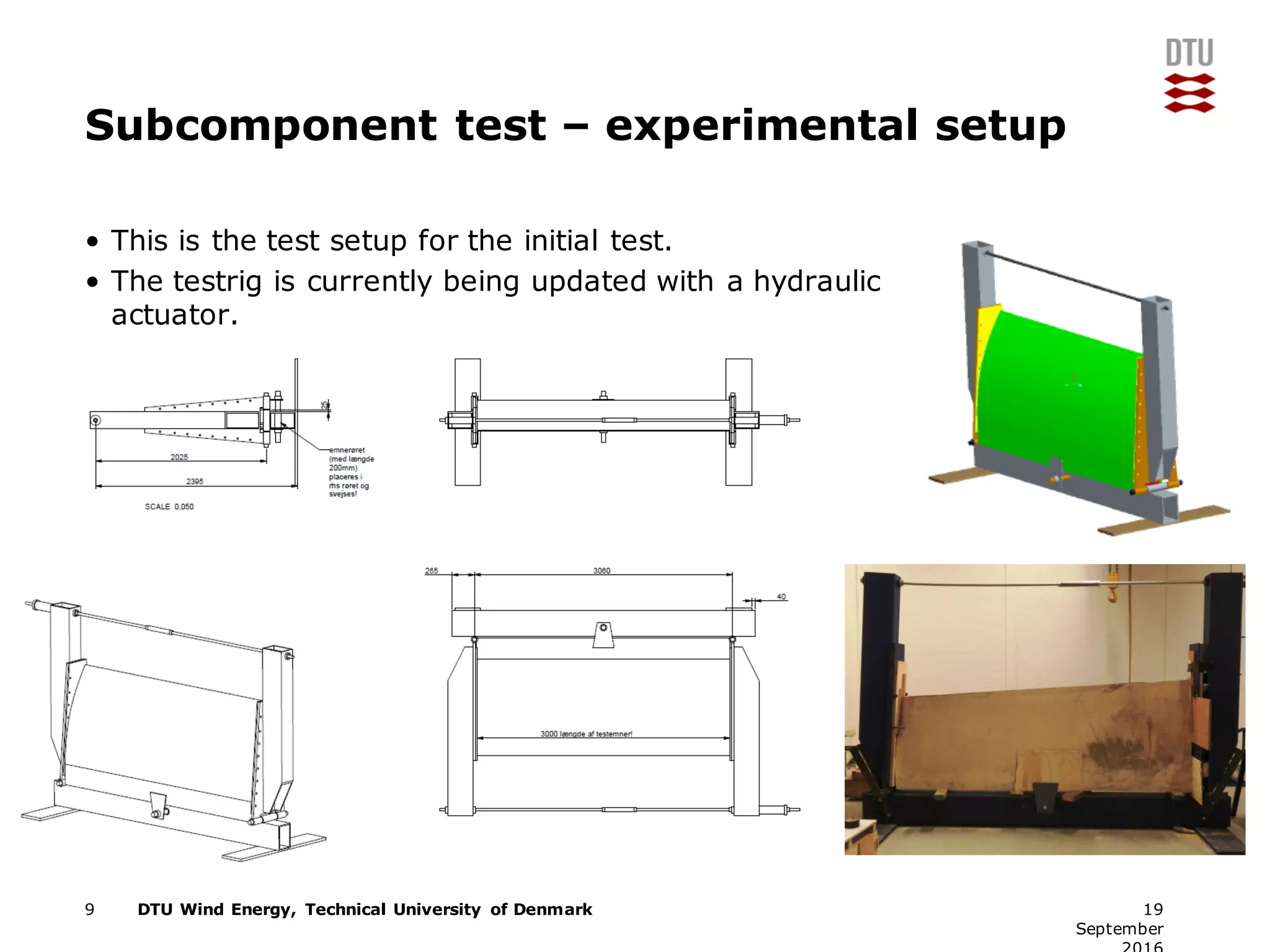
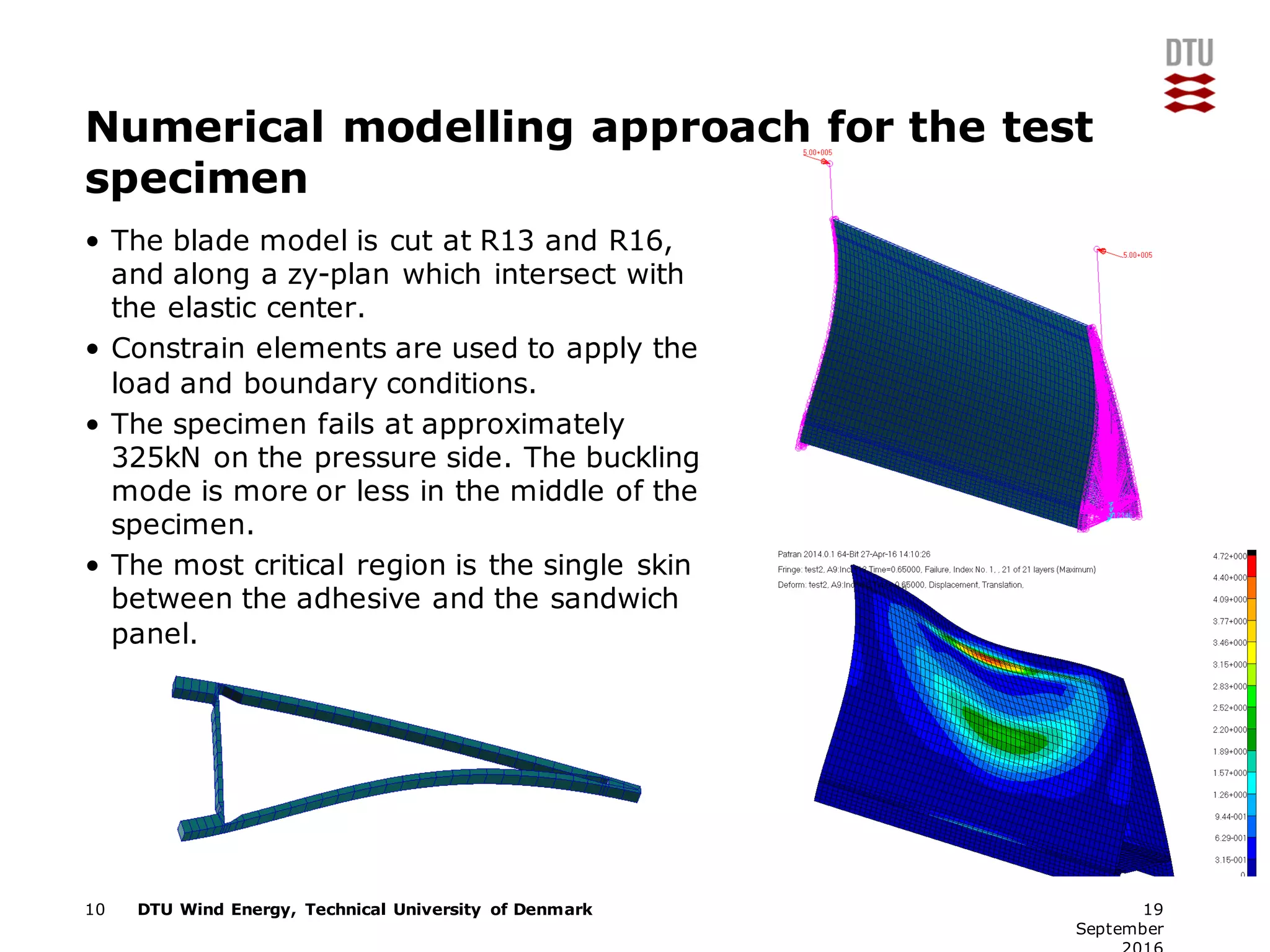
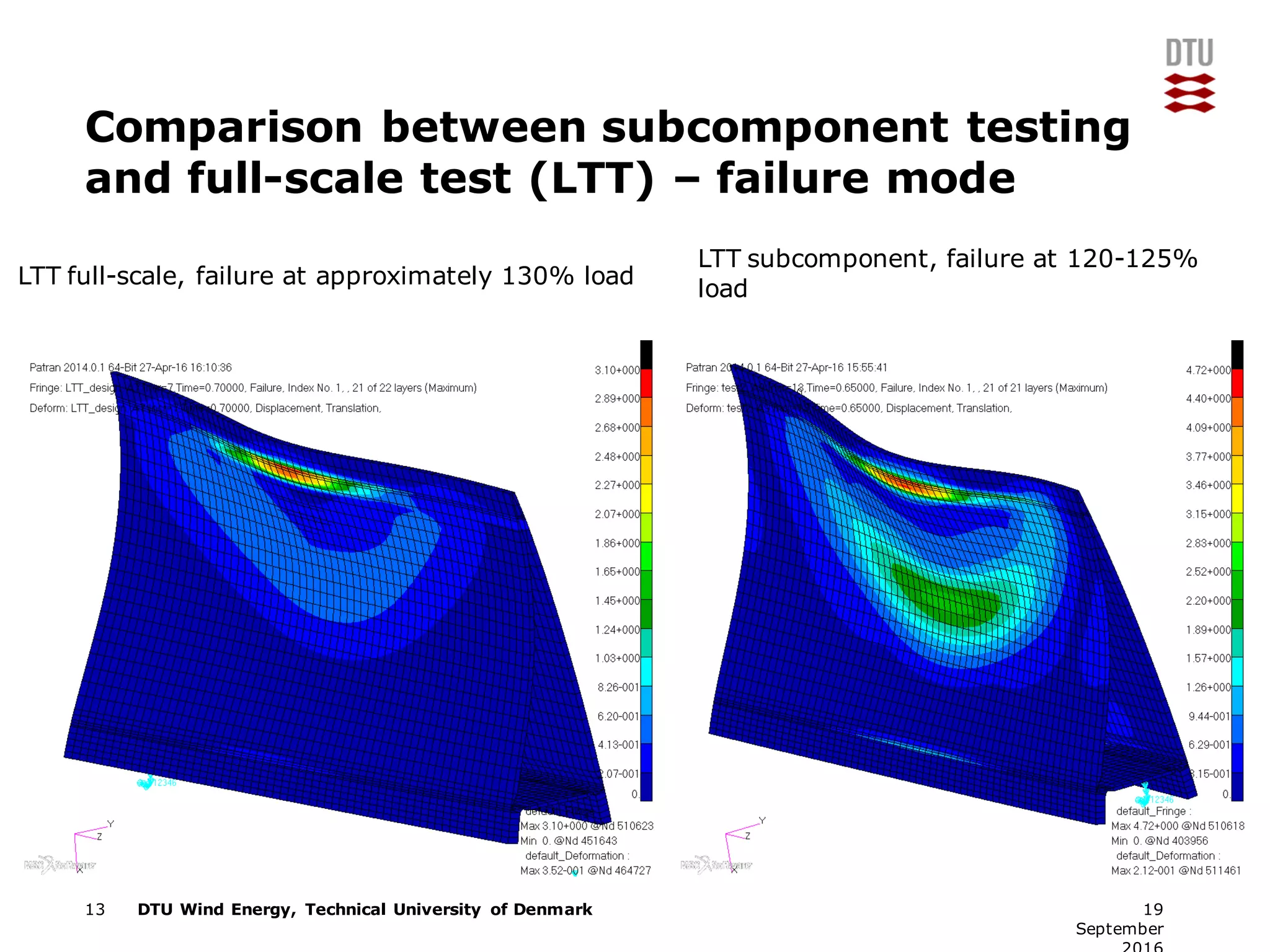
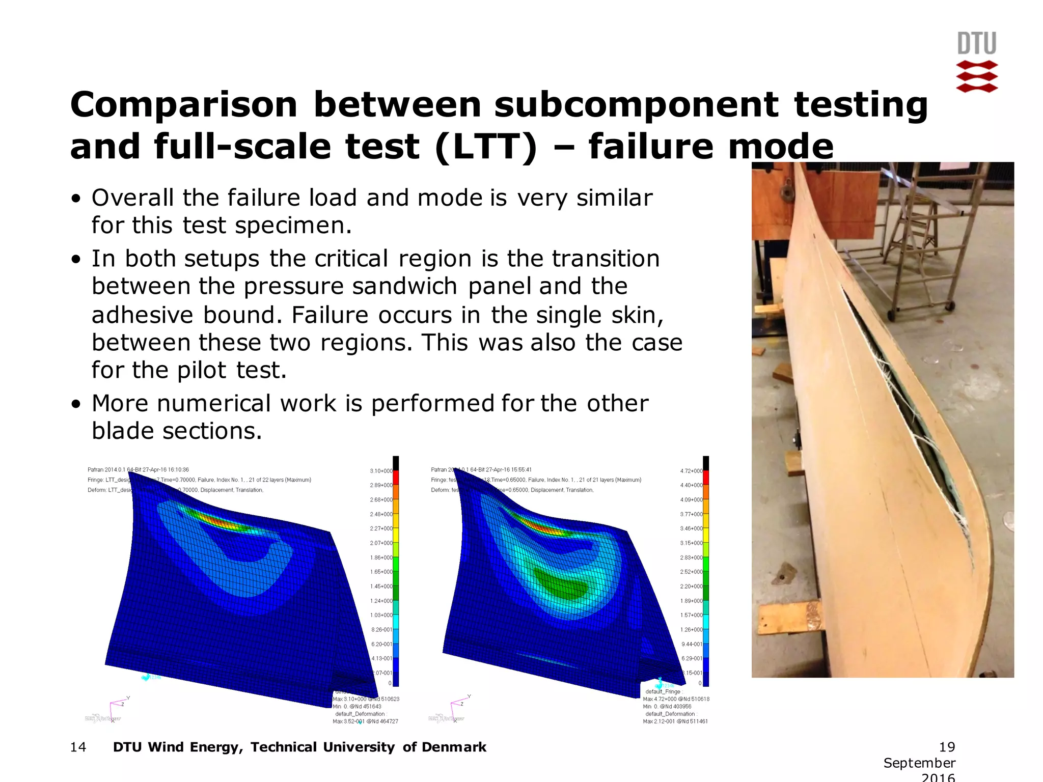
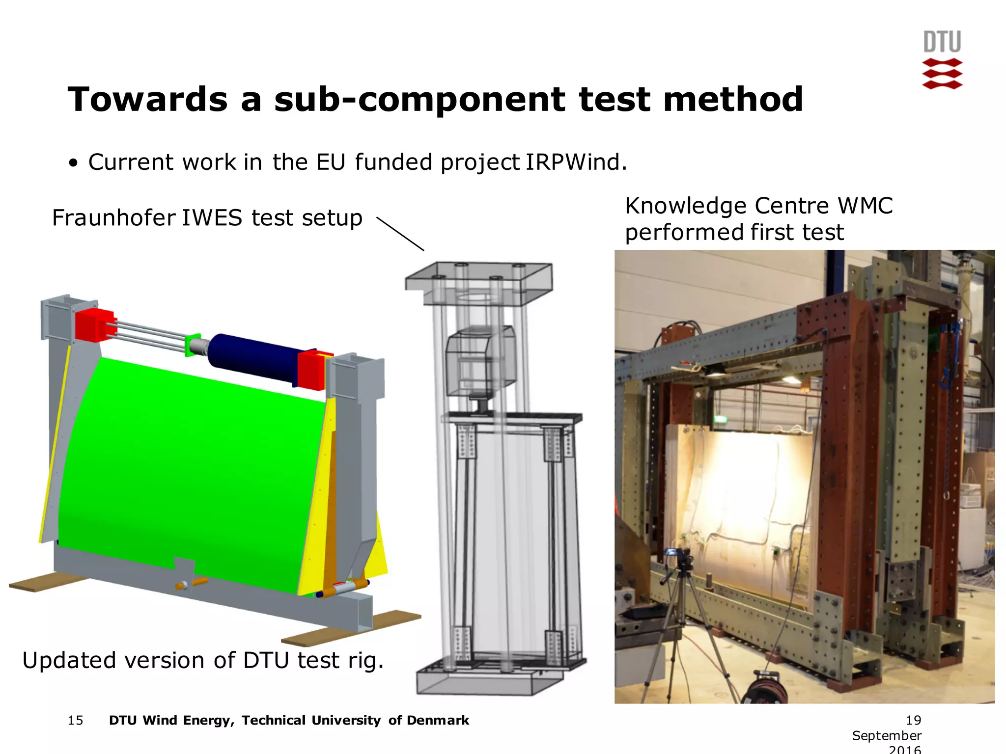
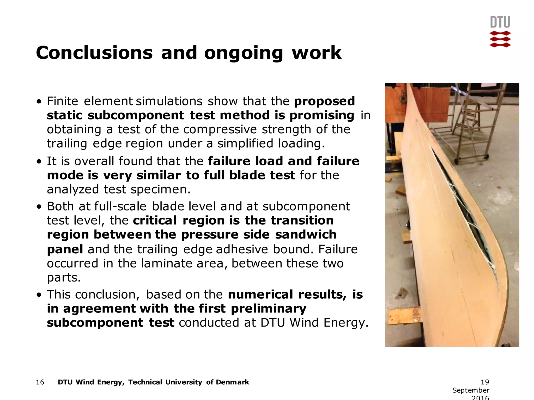

The document discusses developing a new subcomponent test method for the trailing edge region of wind turbine blades. Current blade certification involves full-scale blade testing, but a new standard allows for subcomponent testing. Finite element simulations show that a proposed static subcomponent test produces failure loads and modes similar to full-scale tests for the trailing edge region. Both testing methods show critical failure in the transition between the pressure-side sandwich panel and trailing edge adhesive bond. The subcomponent test is being developed as an industry certification standard to supplement full-scale blade testing.


![Coded Agents – with UiPath SDK + LangGraph [Virtual Hands-on Workshop]](https://cdn.slidesharecdn.com/ss_thumbnails/codedagentsdeck-251215155422-5497c599-thumbnail.jpg?width=640&height=640&fit=bounds)


