Chapter 18(beams of composite materials)
•
6 likes•13,431 views

inayat abbas malla

Recommended
More Related Content
What's hot
What's hot (20)
Viewers also liked
Viewers also liked (13)
Similar to Chapter 18(beams of composite materials)
Similar to Chapter 18(beams of composite materials) (20)
More from himachal pradesh technical university
More from himachal pradesh technical university (13)
Recently uploaded
Recently uploaded (20)
Chapter 18(beams of composite materials)
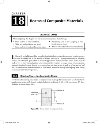
- 1. Stress analysis of composite beam.• What is a reinforced concrete beam?• Stress analysis of reinforced concrete beam.• Preliminary idea of the designing a rein-• forced concrete beam. What is balanced reinforced concrete beam?• Beams of Composite Materials In Chapter 6, we had discussed the normal or longitudinal stresses, also known as the bending stresses, which are developed due to the bending of a beam made up of a homogeneous material following Hooke’s law. However, quite often in practical applications we have to come across beams that are made of two or more materials, called composite materials, which are no longer beams of homogeneous material. Reinforced concrete beam is an example where the beam section is made up of concrete and steel rods. To determine the stresses developed in such beams, we need to modify our foregoing beam theory as discussed in the following section. 18.1 Bending Stress in a Composite Beam For the sake of simplicity, we consider a composite beam made up of two materials A and B and of rect- angular cross-section with Young’s moduli of elasticity as EA and EB (EB > EA), respectively. We show the beam section in Figure 18.1. Learning goaLS After completing this chapter, you will be able to understand the following: 18 Chapter A yo Material A Differential area = dA N Material B Figure 18.1 Cross-section of composite beam. SOM_Chapter 18.indd 755 4/24/2012 8:56:17 PM
- 2. 756 • Chapter 18—Beams of Composite materials If we identify a differential area dA in material A at a distance of y from the neutral axis (NA) of the beam cross-section, then the force in the longitudinal direction acting on that area will be given by d dA A F E y A= - ρ (18.1) This is because dFA is equal to sAdA and sA equals to E∈A. Here ∈A = y/r where r is the radius of curvature of the neutral surface. In a similar way, the same area element dA in the material B will expe- rience a force dFB which is given by d dB BF E y A= - ρ (18.2) However, the same force equation can be written as d dB B A A F E E E y A= - ρ = - E E E y AB A A d ρ = -E y n A A d( ) ρ or d d B AF E y A = - ′ ρ (18.3) where d d d andB A B A ′ = = =A n A E E A n E E Here, n is known as the modular ratio. If EB > EA as assumed earlier, then n is greater than 1. If, how- ever, EB < EA then n is lower than 1. Clearly Eqs. (18.1) and (18.3) indicate that if we transform the entire beam cross-section to material A, then the area of the material B is converted to n times its original area, where, we repeat, n = EB/EA. However, while transforming this area, we must keep y constant and hence, cross-sectional dimen- sion of area of material B is changed parallel to the neutral axis of the section. Also, we must remember that the neutral axis (NA) of the section shell passes through the centroid of the ‘transformed’ section. Figure 18.2 shows the area transformation process of the beam section shown in Figure 18.1 earlier. If the above beam is subjected to positive bending moment, then the stress distribution shown in Figure 18.3 is developed in the original beam cross-section and the ‘transformed’ beam cross- section. In Figure 18.3(a), stress distribution in the original beam cross-section is shown, while in Figure 18.3(b), stress distribution in the transformed equivalent beam cross-section of material A is represented. SOM_Chapter 18.indd 756 4/24/2012 8:56:18 PM
- 3. 18.1 Bending stress in a Composite Beam • 757 If we want to calculate the magnitude of stresses at points P and Q in materials B and A, respectively, we can determine them from the so-called ‘transformed section’ as | | | |σ ρ σ ρ P A P Q A Q and= =E y E y (18.4) However, in reality, magnitude of stress developed at P should be given by | |σ ρ P true B P = E y Multiplying and dividing by EA, we get | |σ ρ P true B A A P = E E E y or | | | |σ σP true P= n (18.5) where | |σP denotes the magnitude of the stress at P in the transformed cross-section. Thus, to get the real stress at P (corresponding to the fact that it belongs to material B with modulus of elasticity EB), we need to multiply the calculated stress by the modular ratio n = EB/EA, where EA is the modulus of elasticity of the material in terms of which the entire area has been transformed. Material A dA h1 h2 N A Material B b N dA dA Material A nb ndA Centroid of the transformed area A h2 h1 Figure 18.2 Area transformation. Material A N NA A Q P Q P yQ Material A yP Material B (a) (b) Figure 18.3 Stress distribution in beams with composite materials. SOM_Chapter 18.indd 757 4/24/2012 8:56:19 PM
- 4. 758 • Chapter 18—Beams of Composite materials exaMpLe 18.1 Two metal strips are solidly bonded to form a metal bar of the cross-section as shown in Figure 18.4. With the given data, calculate the maximum bending moment that can be safely applied to the composite bar (refer Table 18.1). 30 mm 6 mm 6 mm 30 mm Brass Aluminium Brass Figure 18.4 Beam cross-section. table 18.1 material properties Material E (GPa) Allowable Stress (MPa) Brass 105 160 Aluminium 70 100 Solution Let us transform the cross-section of the composite beam to the cross-section of aluminium beam as shown in Figure 18.5. N 6 mm 6 mm 30 mm M P 21 mm 30 mm Q sP sQ A 105 30 70 = 45mm Figure 18.5 Transformed equivalent aluminium section. Here, our modular ratio n = EB/EA = 105/70 = 1.5. Therefore, width of brass section = 30(1.5) mm = 45 mm. SOM_Chapter 18.indd 758 4/24/2012 8:56:20 PM
- 5. 18.1 Bending stress in a Composite Beam • 759 The section, as shown, is symmetric and the neutral axis passes half-way through it. Also, we identify two points P and Q belonging to the section representing farthest points in aluminium and brass sections, respectively. The centroidal area moment of inertia is given by I = + + = 1 12 30 2 1 12 45 6 45 6 18 2440804 3 2 ( ) ( )( ) ( )( )( ) mm44 Now, maximum stresses have been specified in the given data. We can find the transformed stress for the brass as 160/1.5 MPa [from Eq. (18.5)] = 106.67 MPa. Thus, σ σP Q1 MPa and 1 6 67 MPa≤ ≤00 0 . It is known that due to bending moment M applied to the section, a linear stress distribution results as shown in the left half of the figure. Therefore, σ σ Q P Q P = = = y y 21 15 1 4. But σ σ Q P allowable = = < 106 67 100 1 07 1 4 . . . Clearly, we conclude from the above expression that we cannot consider σ σP P allowable = as sQ will be more than the specified limit. We set s s sQ Q allowable PMPa MPa= = ⇒ = =106 67 106 67 1 4 76 2. . . . which is less than σP allowable MPa.= 100 Thus, the safe maximum bending moment M to the section shall correspond to stress of 106.67 MPa at Q. Therefore, sQ Nm 1.24 kNm= ⇒ = ⇒ = = MC I M M106 67 21 244080 1239810 17. ( )( ) . [Answer] exaMpLe 18.2 A composite beam of aluminium strip (EAl = 75 GPa) and a copper strip (ECu = 105 GPa) are bonded together as shown in Figure 18.6. If a bending moment M = 35 Nm is applied about a horizontal axis, calculate the maximum stresses developed in aluminium and copper strips. 24 mm 9 mm 3 mm M N A Aluminium Copper Figure 18.6 Beam section. SOM_Chapter 18.indd 759 4/24/2012 8:56:22 PM
- 6. 760 • Chapter 18—Beams of Composite materials Solution Let us transform the section into an equivalent aluminium section. The modular ratio is n E E = = =Cu Al 105 75 1 4. so the new width of the copper section = (1.4)(24) mm = 33.6 mm. Let us represent the transformed section in Figure 18.7: 24 mm 33.6 mm M N A sP sQ 9 mm 3 mm P Centroid of the transformed section Q y− + Figure 18.7 Transformed section. Now we place the neutral axis (NA) of the section which shall pass through the centroid of the trans- formed equivalent section. Therefore, centroidal height by composite area method is y = + + = ( . )( )( . ) ( )( )( . ) ( . )( ) ( )( ) . 33 6 3 1 5 24 9 7 5 33 6 3 24 9 5 59 mm and centroidal area moment of inertia is I = + + + + 1 12 33 6 3 33 6 3 5 59 5 1 12 24 9 24 9 7 53 2 3 ( . )( ) ( . )( )( . ) ( )( ) ( )( )( . -- = 5 59 4007 78 2 4 . ) . mm In the figure, we show points P and Q belonging to the aluminium and copper sections, respectively, which are farthest from the neutral axis (NA) of the section. So we can calculate the magnitude of the maximum stresses at P and Q as | | ( )( . ) . .maxσ σP Al mm MPa= = - = 35 10 12 5 59 4007 78 55 98 3 2 N and | | ( )( . ) . . .maxσ σQ Cu mm MPa= = × = 35 10 5 59 4007 78 1 4 68 34 3 2 N SOM_Chapter 18.indd 760 4/24/2012 8:56:23 PM
- 7. 18.1 Bending stress in a Composite Beam • 761 Assuming a positive bending moment applied to the section, we conclude that stress in aluminium will be compressive; and that in the copper strip it will be tensile in nature. Thus, maximum stress in the aluminium strip is 55.98 MPa (compressive) and maximum stress in the copper strip is 68.34 MPa (tensile) [Answer] exaMpLe 18.3 Let us consider a composite beam of two materials (1) and (2) having elastic moduli E1 and E2 with E2 < E1 as shown in Figure 18.8. The beam has a circular cross-section of diameter d. Calculate the posi- tion of the centroid of the transformed section which is equivalent to material (1). d 1 2 Figure 18.8 Beam section. Solution From the given condition, the transformed section is equivalent to material (1) and thus, material (2) will become semi-elliptic as shown in Figure 18.9: nd y d O x d/2 d/2 2d/3π 2d/3π Figure 18.9 Transformed section. Clearly, the width of semicircle of material (2) is Width = = E E d nd2 1 SOM_Chapter 18.indd 761 4/24/2012 8:56:24 PM
- 8. 762 • Chapter 18—Beams of Composite materials where n < 1. Now the location of the centroid of the semi-elliptical section, with semi-major axis a = d/2 and semi-minor axis b = nd/2, is determined as follows: 2x dy y O 2b = nd y a = d/2 x2 b2 y2 a2 + = 1 x Figure 18.10 Centroid of semi-ellipse. From Figure 18.10, we get y y A A y x y ab d nd y b a a y a a d = = = - ∫ ∫ ∫ ∫ =d d d d0 0 2 2 2 2 2 2 2 2 2 ( ) / ( / )( / ) / π π yy or y n d ny a y y a = -∫ 16 2 0 2 2 π d = - - - - = -∫ 8 22 2 2 0 2 2 2 2 πd a y a y a y y y a d( ) [as d d( ) ] = - - = 8 2 3 16 32 2 2 3 2 0 2 3 π πd a y d a a ( ) / or y d d d = = 16 3 8 2 32 3 π π The locations of the centroid as measured from the x-axis for the semicircular area and semi-elliptical area are shown in Figure 18.9. Now, applying composite area theorem to Figure 18.10, to determine the centroid of the entire transformed area, we get y d d n d d d n d d = + - + = π π π π π π 2 2 2 2 8 2 3 8 2 3 8 8 2 33 1 1π ( ) ( ) - + n n Thus, the centroid is at a distance of ( / )[( )/( )]2 3 1 1d n nπ - + above from the horizontal diameter. [Answer] SOM_Chapter 18.indd 762 4/24/2012 8:56:26 PM
- 9. 18.1 Bending stress in a Composite Beam • 763 Note: For the transformed section in the above example, we can also determine the centroidal area moment of inertia. It is first determined for the semi-ellipse about the x-axis as I y A y x y b a y a y yxx A a a = = = -∫∫ ∫ ∫ 2 2 0 2 0 2 2 2 2 d d d Putting y = asinq, we get I naxx = ∫2 4 2 0 2 2 sin cos /π θ θ θd or I na na n a n a xx = = - = =∫ ∫ 4 2 0 2 4 0 2 4 2 2 4 1 4 8 sin ( cos ) / /π π θ θ θ θ π π d d 44 128 Now by parallel axis theorem, we get I I Ay n d n d d xx xx= - = - -2 4 2 2 128 8 2 3 π π π = - = - n d nd nd π π π π 4 4 4 128 18 128 1 18 Similarly, for the semicircular portion: I d I d d d dxx xx= = - = - π π π π π π 4 4 2 2 4 128 128 8 2 3 128 1 18 and The centroidal area moment of inertia for the whole section is I nd n d d n n d d xx whole = - + - + + + 4 2 2 128 1 18 8 2 3 1 1 2 3 π π π π π 44 2 2 128 1 18 8 2 3 2 3 1 1 π π π π π - + - - + d d d n n = - + + + +⋅ ⋅ π π π π π π128 1 18 1 8 4 9 4 1 8 4 9 44 2 2 2 2 2 2 2 d n n d d n d d n ( ) ( ) 22 2 1( )+ n = + - + + + + ( ) ( ) ( ) n d d n n d n n 1 128 1 18 2 9 1 2 9 1 4 4 2 4 2 2 π π π π Therefore, I n d d n n xx whole = + - + + ( ) ( ) 1 128 1 18 2 9 1 4 4 π π π The above expression will be required to calculate stresses in such sections. SOM_Chapter 18.indd 763 4/24/2012 8:56:28 PM
- 10. 764 • Chapter 18—Beams of Composite materials exaMpLe 18.4 A rectangular beam is made of a material which has modulus of elasticity Et in tension and Ec in compression (e.g., plastics are examples of these materials which have unequal moduli of elasticity). Writing the flexure equation as 1 ρ = M E Ieq where I bh= 3 /12 (b is the width and h is the depth of the section). Prove that the equivalent modulus of elasticity Eeq is given by E E E E E eq t c t c = +( ) 4 2 Solution Let us assume that the neutral axis (NA) of the section divides the cross-section shown in Figure 18.11: A A b M N N y1 y 2 h y y C1 C2 F F Compression zone (Ec) Tension zone (Et) Figure 18.11 Beam section. Let us assume that NA divides the section in the ratio y1:y2. Therefore, the stresses at points at a distance y above and below the NA are: s r s r comp c tensile tand= =E y E y where r is the radius of curvature of the neutral surface. If we build up an area dA surrounding these points, we get the resultant compressive and tensile forces, which are equal in magnitude. F A A y y = =∫ ∫σ σcomp tensiled d 0 0 1 2 or E yb y E yb y E y E y y y c t c t d d r r0 0 1 2 2 2 1 2 ∫ ∫= ⇒ = Therefore, y y E E y E E E h y E E E h1 2 1 2= ⇒ = + = + t c t t c c t c and (1) SOM_Chapter 18.indd 764 4/24/2012 8:56:30 PM
- 11. 18.2 reinforCed ConCrete Beam • 765 Now, taking moments of the forces about the NA, we get M E y b y E y b y y y = +∫ ∫c td d 0 2 0 21 2 r r = + b E y E y 3 1 3 2 3 r ( )c t Putting y1 and y2 from Eq. (1), we get M bh E E E E E E E E E E E E = + + + +( ) 3 2 3 1 r c t t c t t c t c c t c or M bh E E E E bh E E E E = +( ) = +( ) 3 2 3 2 3 12 1 4 r r t c t c t c t c = IEeq ρ where I bh= 3 12/ . Rearranging, we get 1 ρ = M E Ieq where E E E E E eq t c t c = +( ) 4 2 [Hence proved] 18.2 reinforced Concrete Beam We have already mentioned that reinforced concrete beam is an example of a beam comprising two different materials. It has great practical applications in the field of structural engineering1 . Though the complete discussion on such beams is out of the scope of this book; however, what follows is an elementary beam model for the purpose of an elementary introduction to such important structures. Before we progress further, we make some important assumptions: 1. Concrete is a substance which is weak in tension and strong in compression. Hence, the entire compressive load on the beam section is borne by the concrete, while the steel rod takes up the entire tensile force acting on the beam. 1 An interested reader can go through any standard textbook on the theory of reinforced concrete structures; refer to Reference (1) in the Bibliography section of the book. SOM_Chapter 18.indd 765 4/24/2012 8:56:31 PM
- 12. 766 • Chapter 18—Beams of Composite materials 2. Concrete follows Hooke’s law approximately2 (although it is not quite correct). 3. There is enough cohesive force between the concrete and the steel rods. Essentially, a reinforced concrete beam is made up of concrete and steel rods that are inserted into it from its bottom since the bottom portion is subjected to tensile force as shown in Figure 18.12. The steel rods are covered by a distance of 40–50 mm to protect them from being exposed to any possible fire hazard. Section depth must be assumed to be h. From the foregoing assumption, it is cus- tomary to ignore the concrete portion below NA as it does not carry any tensile force, which is devel- oped in the beam section due to the application of positive bending moment M as shown. We now efficiently transform the section into an equivalent concrete section, wherein the total steel rod area, A N dsteel = × ( / ),p 2 4 (N and d being the number and diameter of the steel rod, respectively) is transformed into area = nAsteel. Since Young’s modulus of steel (Esteel = 200 GPa) is more than that of the concrete (Econc = 25 GPa), steel area is magnified by n = Esteel/Econc 8 times as shown Figure 18.12(b). It is an important task to position the NA in the section defined by the parameter l (0 < l <1) as can be seen from Figure 18.12(b) itself. Since the compressive force developed in the concrete section is equal to the total tensile force developed in the transformed steel section, we get F E yb y E y A E h E E h h = = = -∫ ∫ - ⋅conc steel conc steel c d d r r r l l l 0 0 1 1 ( ) ( ) oonc S A or E b h E E E h Aconc conc steel conc S 2 12 2 ρ λ ρ λ⋅ = -( ) AN M Steel rods, area (total) = Asteel Concrete b h M N A (1−l) lhF b 40−50 mm Area = F Esteel Econc Asteel (a) (b) Figure 18.12 (a) Reinforced concrete beam section, (b) equivalent concrete section. 2 Refer to Reference (12) in the Bibliography section of the book. SOM_Chapter 18.indd 766 4/26/2012 4:52:36 PM
- 13. 18.2 reinforCed ConCrete Beam • 767 bh n A 2 12 = -λ λ( ) steel (18.6) where n = Esteel/Econc, which is the modular ratio. The above equation can be solved for l to obtain the position of NA. To determine the second area moment of inertia, we write I b h h nA= + - ⋅ 1 3 13 2 2 ( ) ( )λ λ steel (18.7) Clearly, stresses in the concrete and steel rods due to M can be determined as and σ λ conc = M h I ( ) σ λ steel = - n M h I ( )1 (18.8) For a given bending moment M, the stresses calculated as per the above equations must be less than or equal to the allowable stresses in the concrete and steel rods. Conversely, if stresses are specified, the moment can be calculated using the above equations; and the maximum bending moment that can be applied to the reinforced concrete beam is given by M I h I n h max , ( ) = - ⋅ Min conc steels l s l1 (18.9) exaMpLe 18.5 For the reinforced concrete beam shown in Figure 18.13, find the maximum bending moment M that can safely be applied to the section. Assume the modular ratio, n to be 15 for the grade of concrete used, the allowable stress of steel, ssteel = 125 MPa and that of concrete, sconc = 4.5 MPa. A 250 mm 150 mm N M Asteel = 450 mm2 Figure 18.13 Reinforced beam section of Example 18.5. SOM_Chapter 18.indd 767 4/26/2012 4:52:37 PM
- 14. 768 • Chapter 18—Beams of Composite materials Solution The neutral axis (NA) position locator, l can be found from the Eq. (18.6): bh nA nA bh2 1 2 12 2 = - ⇒ = -l l l lsteel steel ( ) ( ) Putting the given values in the above equation, we get λ λ λ2 2 15 450 150 250 1 0 36 1= × × - = - ( )( ) ( ) . ( ) Solving, we get λ = - ± + = 0 36 0 36 4 0 36 2 0 446 2 . . ( . ) . (ignoring the negative impossibble root) From Eq. (18.7), I b h h n A= + - 1 3 13 2 2 ( ) ( )λ λ S = × + - 1 3 150 0 446 250 1 0 446 250 15 4503 2 2 ( )( . ) ( . ) ( ) ( )( ) or I = ×198 79 106 4 . mm Now from Eq. (18.9), we get M I h I n h max , , ( ) = - Min conc steelσ λ σ λ1 = × × × - × ⋅ ⋅ Min 4 5 198 19 10 0 446 250 125 198 19 10 15 1 0 446 2 9 9 . ( ) . , ( ) ( . ) 550 = = = Min Nmm Nmm Nmm kNm ( . , . ) . . 8022914 8 11960890 5 8022914 8 8 02 Thus, the safe moment that can be applied to the section is Mmax = 8.05 kNm. [Answer] SOM_Chapter 18.indd 768 4/24/2012 8:56:35 PM
- 15. 18.2 reinforCed ConCrete Beam • 769 exaMpLe 18.6 The reinforced concrete beam shown in Figure 18.14 is subjected to the bending moment M = +175 kN m. If Esteel = 200 GPa and Econc = 25 GPa, calculate the maximum stresses developed in the steel and concrete rods. A 450 mm 250 mm N M 50 mm 22 mm diameter steel rod (4 numbers) Figure 18.14 Reinforced concrete beam section. Solution For the given problems, Asteel mm mm= × =4 4 22 1520 52 2 2 ( / )( ) .π and the modular ratio, n E E= = =steel conc/ /200 25 8 n E E= = =steel conc/ / .200 25 8 0 . Clearly, the neutral axis (NA) locator l in the equivalent concrete section is given by the Eq. (18.6) as λ λ λ λ2 2 1 2 8 1520 5 250 400 1 0 243 1= - = × × × - = - nA bh steel ( ) . ( ) . ( ) (note that h = 450 - 50 = 400 mm). Therefore, λ = - + + = 1 2 0 243 0 243 4 0 24 0 3862 . . ( . ) . Now, from Eq. (18.7) I b b h nA= + - 1 3 13 2 2 ( ) ( ) ( )l l steel = × + - × × × 1 3 250 0 386 400 1 0 386 400 8 1520 53 2 2 ( )( . ) ( . ) ( . ) or mmI = ×1 0405 109 4 . By using stress equations from Eq. (18.8), we get σ λ conc = M h I ( ) SOM_Chapter 18.indd 769 4/24/2012 8:56:37 PM
- 16. 770 • Chapter 18—Beams of Composite materials or N/mm MPaconcσ = × = 175 10 0 386 400 1 0405 10 25 97 6 9 2( )( . ) . ( ) . and σ λ steel N/mm= - = - n M h I ( ) . ( )( . )( ) . ( ) 1 8 0 175 10 1 0 386 400 1 0405 10 6 9 22 or σsteel MPa= 330 5. Thus, the maximum stresses developed in the concrete is 26.0 MPa (compressive) and 330.5 MPa (tensile). [Answer] Note: We observe from the stress equations in Eq. (18.8) that the ratio of the maximum stress in the steel to that in concrete is r n n= = - = - σ σ λ λ λ steel conc 1 1 1 and from Eq. (18.6), we note that: l = + - = 1 2 4 22 k k k k nA bh ; steel 1 2 4 1 2 4 2 2 λ = + - = + + k k k k k k k or 1 1 4 2 1 2 1 4 2 1 2 1 2 4 2 2 2 λ λ - = + + - = + - = + - = k k k k k k k k k k k So the maximum stress ratio is r n k = = σ σ λsteel conc Sometimes, beams are designed in such a way that the maximum stresses in the concrete and steel rods are equal to their specified allowable values. These beams are called balanced reinforced concrete beams. In order to design a reinforced concrete beam as a balanced one, we need to posi- tion the neutral axis (NA) locator, l. If the specified stresses are (sconc)allowable and (ssteel)allowable for concrete and steel, respectively, then l can be found as: n 1 1 λ σ σ - = ( ) ( ) steel allowable conc allowable or steel allowable conc allowable steel allowa1 1 1 1 λ σ σ σ = + = + ( ) ( ) ( ) n bble conc allowable conc steel( )σ ⋅ E E SOM_Chapter 18.indd 770 4/24/2012 8:56:38 PM
- 17. 18.2 reinforCed ConCrete Beam • 771 λ σ σ = + ⋅ 1 1 ( ) ( ) steel allowable concrete allowable concrete steel E E (18.10) The above expression locates the NA in balanced beam. exaMpLe 18.7 A reinforced concrete beam is designed to carry a bending moment, M = 10.4 kN. The width b and depth h of the section are related as h = 1.5 b. Assume ssteel = 125 MPa, sconc = 4.0 MPa, Esteel = 210 GPa and Econc = 14 GPa. Design the beam. Solution We first determine the locator of NA using the specified stress ratios from Eq. (18.10) as: λ σ σ = + = +⋅ 1 1 1 1 125 4 ( ) ( ) steel allowable conc allowable conc steel E E .. . 0 14 210 0 324 ⋅ = (1) AN M M N Steel rods total area = Asteel b h 40–50 mm A n Asteel (1−l)h lh 2lh/3 F = Asteel(ssteel)allowable F = 1 2 (sconc)allowable (lh)(b) (sconc)allowable (ssteel)allowable n Figure 18.15 Concrete beam. Now from the equivalent diagram shown in Figure 18.15 using the stress distribution, we get 1 2 ( ) ( )σ λ σconc allowable steel steel allowablebh A= bh Asteel = =2 2 125 0 324 4 ( ) ( ) ( . )( σ λ σ steel allowable conc allowable .. ) . 0 192 9= (2) Again from the stress distribution of the equivalent concrete section, by equating the internal moment with the applied bending moment, we get: SOM_Chapter 18.indd 771 4/24/2012 8:56:40 PM
- 18. 772 • Chapter 18—Beams of Composite materials or F h h h M Fh M 2 3 1 2 3 λ λ λ + - = - = But F A= steel steel allowable( )σ . So, the above equation becomes: A h Msteel steel allowable1 2 3 - = λ σ( ) Putting l from Eq. (1), we get ( )( ) ( ) . ( ) . A h M steel steel allowable = - = - × 1 2 3 10 4 10 1 2 0 3 6 λ σ 224 3 125 ( ) ( )( ) .A hsteel = 93273 54 2 mm (3) Now from Eqs. (2) and (3), we get bh2 = (192.9)(93273.54) as it is known that h = 1.5b or b = h/1.5, we get h h3 1 5 192 9 93273 54 299 96 300= ⇒ =( . )( . )( . ) . mm mm Thus, section width, b = 300/1.5 = 200 mm and the steel area is Asteel = 93273.54/h = 93273.54/300 = 310.9 mm2 Using 10 mm steel rods, we have number of steel rods = N = 310.9/[(p/4) (10)2 ] = 3.96 ≈ 4. Thus we design the beam as shown in Figure 18.16. 200 mm 300 mm 50 mm f10 rods, 4 numbers Figure 18.16 Designed beam cross-section. [Answer] SOM_Chapter 18.indd 772 4/24/2012 8:56:41 PM
- 19. numeriCal proBlems • 773 Summary In this chapter, we have elaborated our earlier knowledge of stress equation of beam, which was developed for a homogenous beam material, to the cases where different materials are used to form composite beams. To this end, we have introduced the concept of equivalent section and successfully applied stress equation for composite beams. We have also given a careful attention to a special case of composite beam of practical impor- tance, known as reinforced concrete beams. Some design aspects for such beams are also discussed in order to introduce the reader to a specialised topic on the theory of concrete structures. Key terms Normal stress Longitudinal stress Bending stress Composite area method Homogeneous material Neutral axis Transformed section Modular ratio Reinforced concrete beam Balanced reinforced concrete beam review Questions 1. What do you mean by beams of composite materials? 2. Explain the transformed section of a com- posite beam. 3. What do you mean by reinforced concrete beam? 4. What are the assumptions of stress analysis of a reinforced concrete beam? 5. What do you understand by balanced rein- forced concrete beam? numerical problems 1. A simply supported beam with 3 m span carries a concentrated load P = 10 kN acting at its midpoint. The beam is made of wood and steel and has cross-section as shown in Figure 18.17. Assuming modular ratio Ewood/ Esteel = 0.05, calculate the stresses developed in steel and wood. Figure 18.17 Problem 1. 150 mm 10 mm 100 mm Wood Steel SOM_Chapter 18.indd 773 4/24/2012 8:56:42 PM
- 20. 774 • Chapter 18—Beams of Composite materials 2. A composite beam has a circular cross- section as shown in Figure 18.18. If Ebrass = 103 GPa and EAl = 70 GPa and moment M = 904 Nm is applied to the section, calcu- late the maximum stresses in brass and aluminium. Brass Aluminium r = 20 mm Figure 18.18 Problem 2. [Hint: Use the results of Example 18.3.] 3. For the reinforced concrete beam shown in Figure 18.19, the bending moment applied is M = +203 kN m. Calculate the stresses in concrete and steel. Assume Econc = 25 GPa, Esteel = 200 GPa. 62.5 mm 125 mm Steel rods (25 mm diameter) 600 mm 300 mm 750 mm Figure 18.19 Problem 3. 4. For the concrete shown in Figure 18.20, Econc = 16.67 GPa and Esteel = 200 GPa. Find Mmax if (sconc)allowable = 12 MPa and (ssteel)allowable = 110 MPa. 300 mm 360 mm Steel rods (25 mm diameter) Figure 18.20 Problem 4. answers Numerical Problems 1. ssteel = 77.5 MPa (tensile); swood = 12.4 MPa (compressive) 2. sbrass = 155 MPa (compressive); ssteel = 123 MPa (tensile) 3. ssteel = 200 MPa (tensile), sconc = 8.0 MPa (compressive) 4. Mmax = 50 kNm SOM_Chapter 18.indd 774 4/24/2012 8:56:43 PM