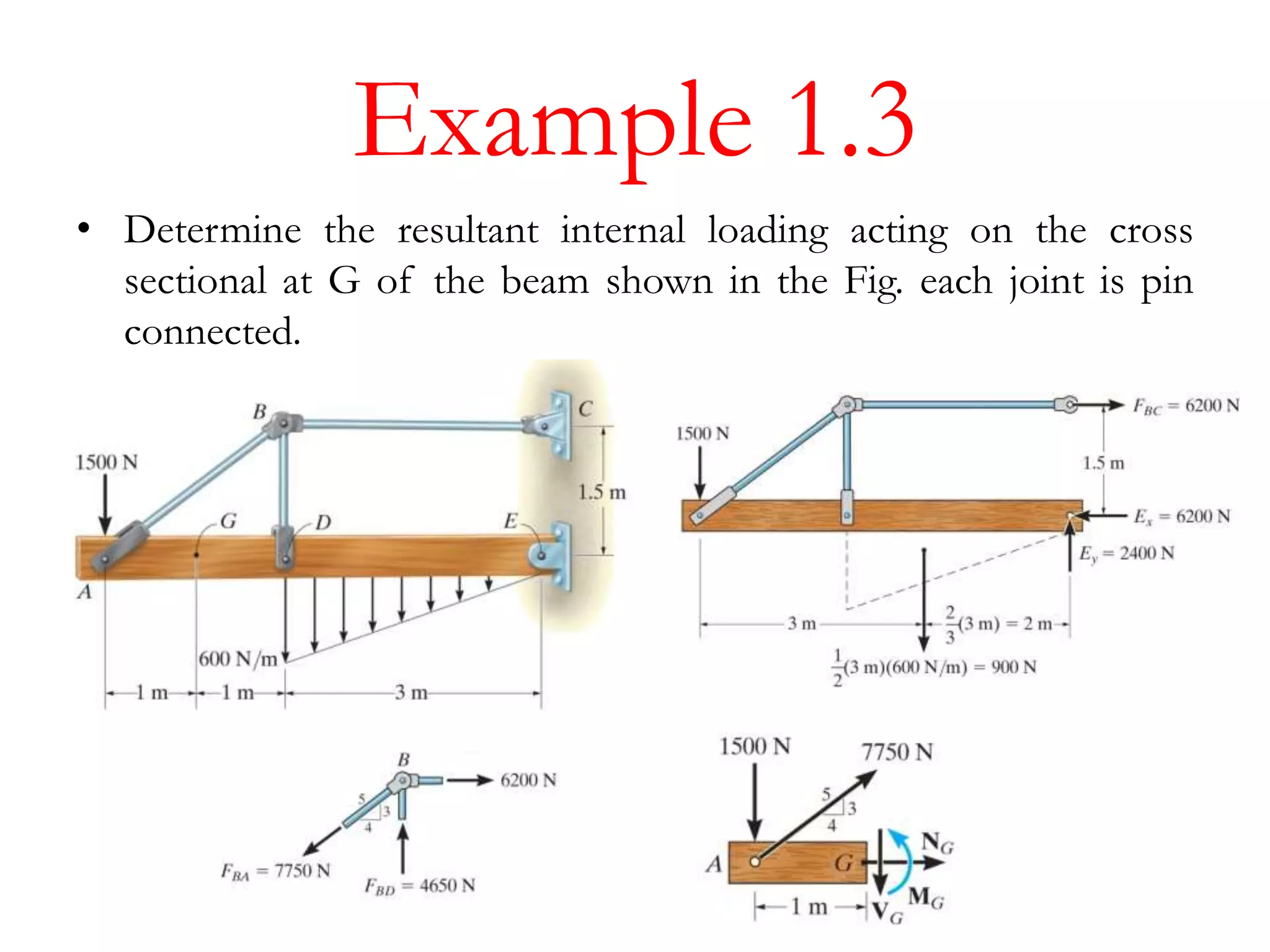
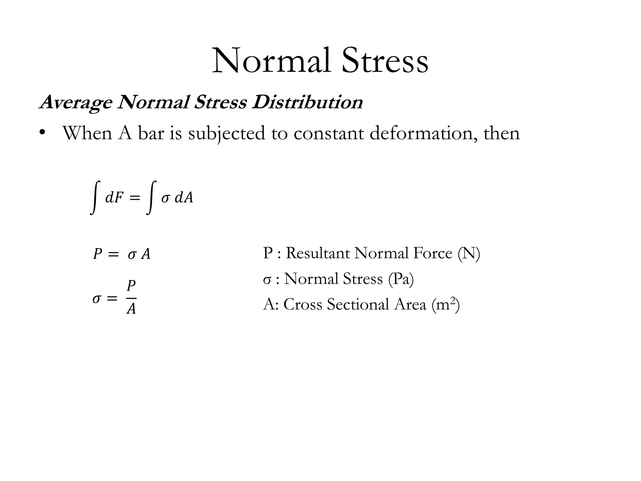
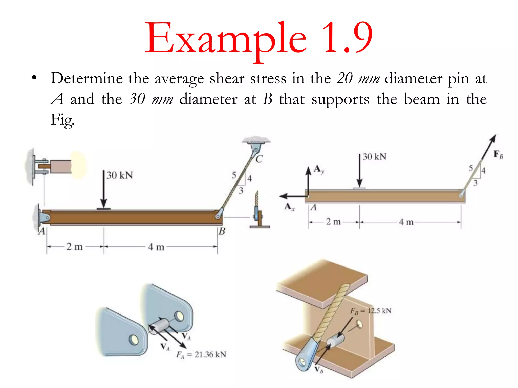
Introduction
• Mechanics of materials is a study of the relationship between the
external loads on a body and the intensity of the internal loads
within the body.
• This subject also involves the deformations and stability of a body
when subjected to external forces.
Equilibrium of a Deformable Body
External Forces:
1. Surface Forces: caused by direct contact of other body’s surface
2. Body Forces: other body exerts a force without contact
Support Reactions
• Surface forces developed at the supports/points of contact
between bodies
Equilibrium of a Deformable Body
Equations of Equilibrium
• Equilibrium of a body requires a balance of forces and a balance
of moments
• For a body with x, y, z coordinate system with origin O (3D
Space)
• Best way to account for these forces is to draw the body’s free-
body diagram (FBD).
𝐹 = 0 𝑀 𝑜 = 0
𝐹𝑥 = 0, 𝐹𝑦 = 0, 𝐹𝑧 = 0
𝑀 𝑥 = 0 , 𝑀 𝑦 = 0, 𝑀𝑧 = 0
Equilibrium of a Deformable Body
Internal Resultant Loadings
• Objective of FBD is to determine the
resultant force and moment acting
within a body.
• In general, there are 4 different types
of resultant
• loadings:
• a) Normal force, N
• b) Shear force, V
• c) Torsional moment or torque, T
• d) Bending moment, M
Example 1.1
• Determine the resultant internal loading acting on the cross section
at C of the cantilevered beam shown in the Fig.
Example 1.3
• Determine the resultant internal loading acting on the cross
sectional at G of the beam shown in the Fig. each joint is pin
connected.
Stress
• Normal Stress σ : Force per unit area acting normal
• Shear Stress τ: Force per unit area acting tangent
Average Normal Stress in an Axially
Loaded Bar
When a cross-sectional area bar is subjected to axial force through
the centroid, it is only subjected to normal stress. Stress is assumed
to be averaged over the area.
Normal Stress
Average Normal Stress Distribution
• When A bar is subjected to constant deformation, then
P : Resultant Normal Force (N)
σ : Normal Stress (Pa)
A: Cross Sectional Area (m2)
𝑑𝐹 = 𝜎 𝑑𝐴
𝑃 = 𝜎 𝐴
𝜎 =
𝑃
𝐴
Example 1.5
• The bar shown in the Fig., has a constant width of 35 mm and a
thickness of 10 mm. Determine the maximum average normal
stress in the bar when it is subjected to the loading shown?
Example 1.6
• The 80 kg lamp is supported by two rods AB and BC as shown in
the Fig. If the AB has a diameter of 10 mm and BC has a
diameter of 8 mm. Determine the average normal stress in each
rod.
Average Shear Stress
• The average shear stress distributed over each sectional that
develops a shear force.
τ: Average Shear Stress
V: Resultant Internal Shear Force
A: Area at the Section
• Different types of Shear
1. Single Shear
2. Double Shear
𝜏 𝑎𝑣𝑔 =
𝑉
𝐴
Example 1.9
• Determine the average shear stress in the 20 mm diameter pin at
A and the 30 mm diameter at B that supports the beam in the
Fig.
Allowable Stress
• Many unknown factors that influence the actual stress in a
member.
• A factor of safety is needed to obtained allowable load.
• The factor of safety (F.S.) is a ratio of the failure load divided by
the allowable load
𝐹. 𝑆 =
𝐹𝑓𝑎𝑖𝑙
𝐹𝑎𝑙𝑙𝑜𝑤𝑎𝑏𝑙𝑒
𝐹. 𝑆 =
𝜎𝑓𝑎𝑖𝑙
𝜎 𝑎𝑙𝑙𝑜𝑤𝑎𝑏𝑙𝑒
𝐹. 𝑆 =
𝜏 𝑓𝑎𝑖𝑙
𝜏 𝑎𝑙𝑙𝑜𝑤𝑎𝑏𝑙𝑒
Example 1.12
• The control arm is subjected to the loading shown in the Fig.,
determine the required diameter of the steel pin at C if the
allowable shear stress for the steel is 55 MPa.

Normal stress & Shear Stress

  • 1.
    Introduction • Mechanics ofmaterials is a study of the relationship between the external loads on a body and the intensity of the internal loads within the body. • This subject also involves the deformations and stability of a body when subjected to external forces.
  • 2.
    Equilibrium of aDeformable Body External Forces: 1. Surface Forces: caused by direct contact of other body’s surface 2. Body Forces: other body exerts a force without contact
  • 3.
    Support Reactions • Surfaceforces developed at the supports/points of contact between bodies
  • 4.
    Equilibrium of aDeformable Body Equations of Equilibrium • Equilibrium of a body requires a balance of forces and a balance of moments • For a body with x, y, z coordinate system with origin O (3D Space) • Best way to account for these forces is to draw the body’s free- body diagram (FBD). 𝐹 = 0 𝑀 𝑜 = 0 𝐹𝑥 = 0, 𝐹𝑦 = 0, 𝐹𝑧 = 0 𝑀 𝑥 = 0 , 𝑀 𝑦 = 0, 𝑀𝑧 = 0
  • 5.
    Equilibrium of aDeformable Body Internal Resultant Loadings • Objective of FBD is to determine the resultant force and moment acting within a body. • In general, there are 4 different types of resultant • loadings: • a) Normal force, N • b) Shear force, V • c) Torsional moment or torque, T • d) Bending moment, M
  • 6.
    Example 1.1 • Determinethe resultant internal loading acting on the cross section at C of the cantilevered beam shown in the Fig.
  • 7.
    Example 1.3 • Determinethe resultant internal loading acting on the cross sectional at G of the beam shown in the Fig. each joint is pin connected.
  • 8.
    Stress • Normal Stressσ : Force per unit area acting normal • Shear Stress τ: Force per unit area acting tangent
  • 9.
    Average Normal Stressin an Axially Loaded Bar When a cross-sectional area bar is subjected to axial force through the centroid, it is only subjected to normal stress. Stress is assumed to be averaged over the area.
  • 10.
    Normal Stress Average NormalStress Distribution • When A bar is subjected to constant deformation, then P : Resultant Normal Force (N) σ : Normal Stress (Pa) A: Cross Sectional Area (m2) 𝑑𝐹 = 𝜎 𝑑𝐴 𝑃 = 𝜎 𝐴 𝜎 = 𝑃 𝐴
  • 11.
    Example 1.5 • Thebar shown in the Fig., has a constant width of 35 mm and a thickness of 10 mm. Determine the maximum average normal stress in the bar when it is subjected to the loading shown?
  • 12.
    Example 1.6 • The80 kg lamp is supported by two rods AB and BC as shown in the Fig. If the AB has a diameter of 10 mm and BC has a diameter of 8 mm. Determine the average normal stress in each rod.
  • 13.
    Average Shear Stress •The average shear stress distributed over each sectional that develops a shear force. τ: Average Shear Stress V: Resultant Internal Shear Force A: Area at the Section • Different types of Shear 1. Single Shear 2. Double Shear 𝜏 𝑎𝑣𝑔 = 𝑉 𝐴
  • 14.
    Example 1.9 • Determinethe average shear stress in the 20 mm diameter pin at A and the 30 mm diameter at B that supports the beam in the Fig.
  • 15.
    Allowable Stress • Manyunknown factors that influence the actual stress in a member. • A factor of safety is needed to obtained allowable load. • The factor of safety (F.S.) is a ratio of the failure load divided by the allowable load 𝐹. 𝑆 = 𝐹𝑓𝑎𝑖𝑙 𝐹𝑎𝑙𝑙𝑜𝑤𝑎𝑏𝑙𝑒 𝐹. 𝑆 = 𝜎𝑓𝑎𝑖𝑙 𝜎 𝑎𝑙𝑙𝑜𝑤𝑎𝑏𝑙𝑒 𝐹. 𝑆 = 𝜏 𝑓𝑎𝑖𝑙 𝜏 𝑎𝑙𝑙𝑜𝑤𝑎𝑏𝑙𝑒
  • 16.
    Example 1.12 • Thecontrol arm is subjected to the loading shown in the Fig., determine the required diameter of the steel pin at C if the allowable shear stress for the steel is 55 MPa.