

Recommended
More Related Content
What's hot
What's hot (20)
Viewers also liked
Viewers also liked (20)
Similar to Bridge Rectifier
Similar to Bridge Rectifier (20)
More from DoCircuits
More from DoCircuits (20)
Recently uploaded
Recently uploaded (20)
Bridge Rectifier
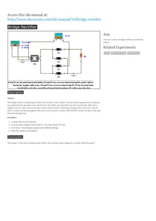
- 1. Access this lab-manual at: http://www.docircuits.com/lab-manual/19/bridge-rectifier Bridge Rectifier Aim Aim is to connect a bridge rectifier and verify the output. Related Experiments DIODE Description Theory: The bridge rectifier is another type of full-wave rectifier. It has 4 diodes. The two function generators are replaced by a single function generator and a transformer. This makes sure that when one end is positive the other end is negative and vice versa. Thus at any time only two diodes will be conducting. During positive half-cycle, only D0 and D1 conduct and during negative half-cycle, only D2 and D3 conduct. And both the currents will pass in the same direction through load. Procedure: 1. 2. 3. 4. Connect the circuit as shown. Give an input voltage of 50 Hz and 6 V. Use load resistor of 1 kΩ. Go to Run › Time Domain analysis with defaukt settings View the results on the plotter Conclusion The output is a full-wave rectified output. What is the minimum input voltage do you think should be given? BRIDGE RECTIFIER RECTIFICATION