

Recommended
More Related Content
Similar to BJT characteristics
Similar to BJT characteristics (20)
More from DoCircuits
More from DoCircuits (20)
Recently uploaded
Recently uploaded (20)
BJT characteristics
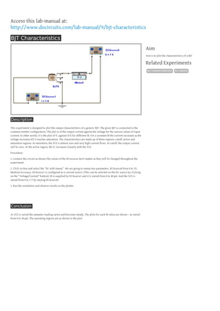
- 1. Access this lab-manual at: http://www.docircuits.com/lab-manual/9/bjt-characteristics BJT Characteristics Aim Aim is to plot the characteristics of a BJT Related Experiments BJT CHARACTERISTICS Description This experiment is designed to plot the output characteristics of a generic BJT. The given BJT is connected in the common emitter configuration. The plot is of the output current against the voltage for the various values of input current. In other words, it is the plot of IC against VCE for different IB. For a constant IB the current increases as the voltage increases till it reaches saturation. The characteristics are made up of three regions: cutoff, active and saturation regions. At saturation, the VCE is almost zero and very high current flows. At cutoff, the output current will be zero. At the active region, the IC increases linearly with the VCE. Procedure: 1. Connect the circuit as shown.The values of the DCsources don’t matter as they will be changed throughout the experiment. 2. Click on Run and select the “DC with Sweep”. We are going to sweep two parameters. DCSource0 from 0 to 2V, Medium Accuracy. DCSource1 is configured as a current source. (This can be selected on the DC source by clicking on the “Voltage/Current” button). IB is supplied by DCSource1 and it is varied from 0 to 40 μA. And the VCE is varied from 0 to 2 V by varying DCSource0. 3. Run the simulation and observe results on the plotter. Conclusion As VCE is varied the ammeter reading varies and becomes steady. The plots for each IB value are shown – as varied from 0 to 40 μA. The operating regions are as shown in the plot. BJT BASICS