Downloaded 146 times

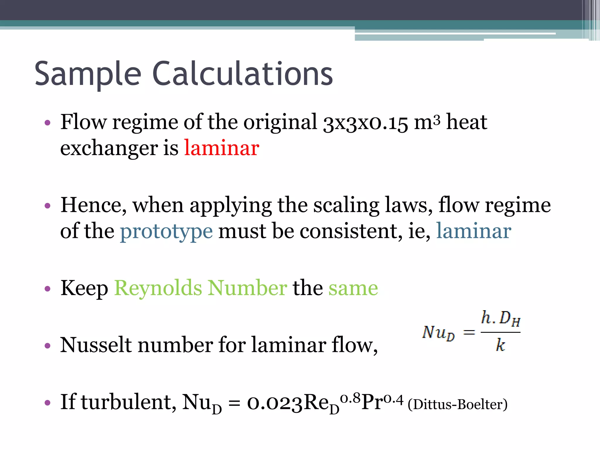
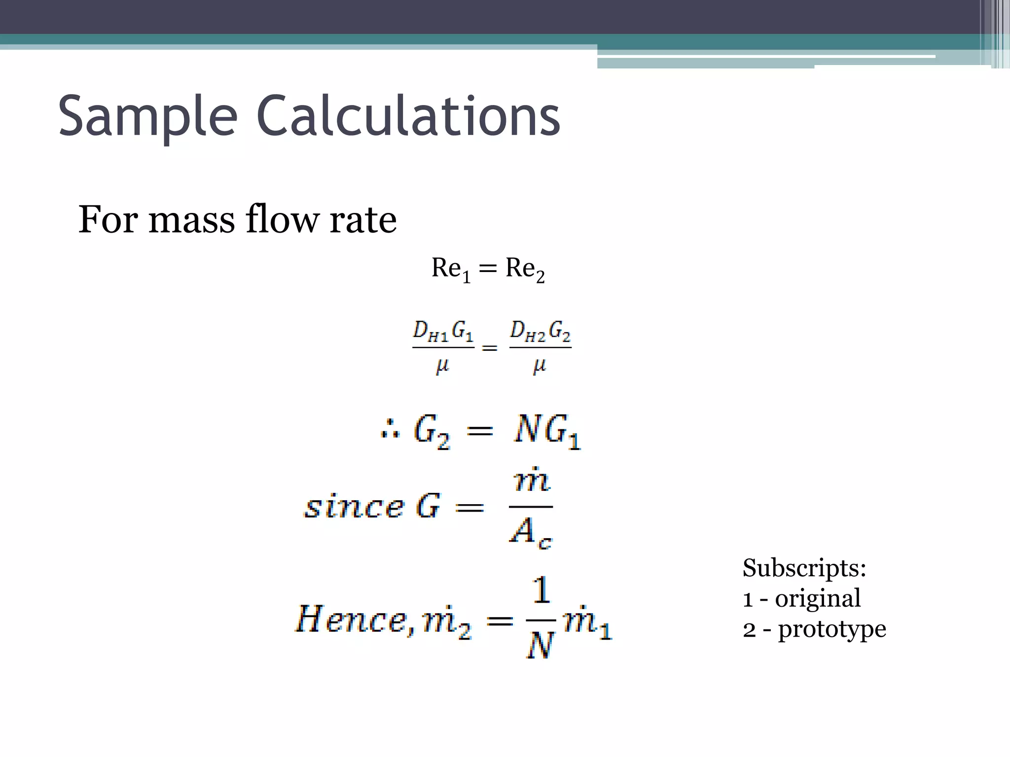
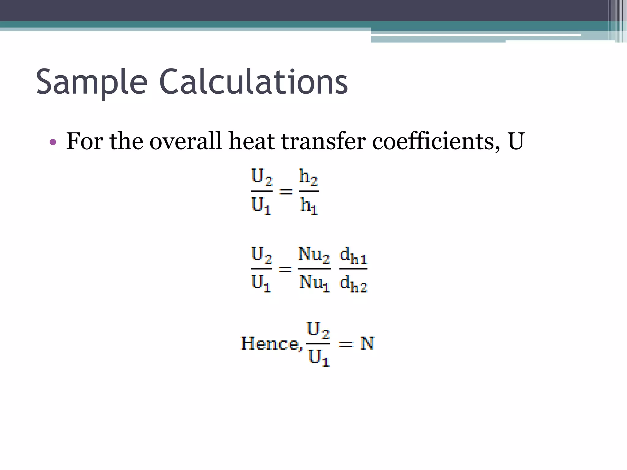
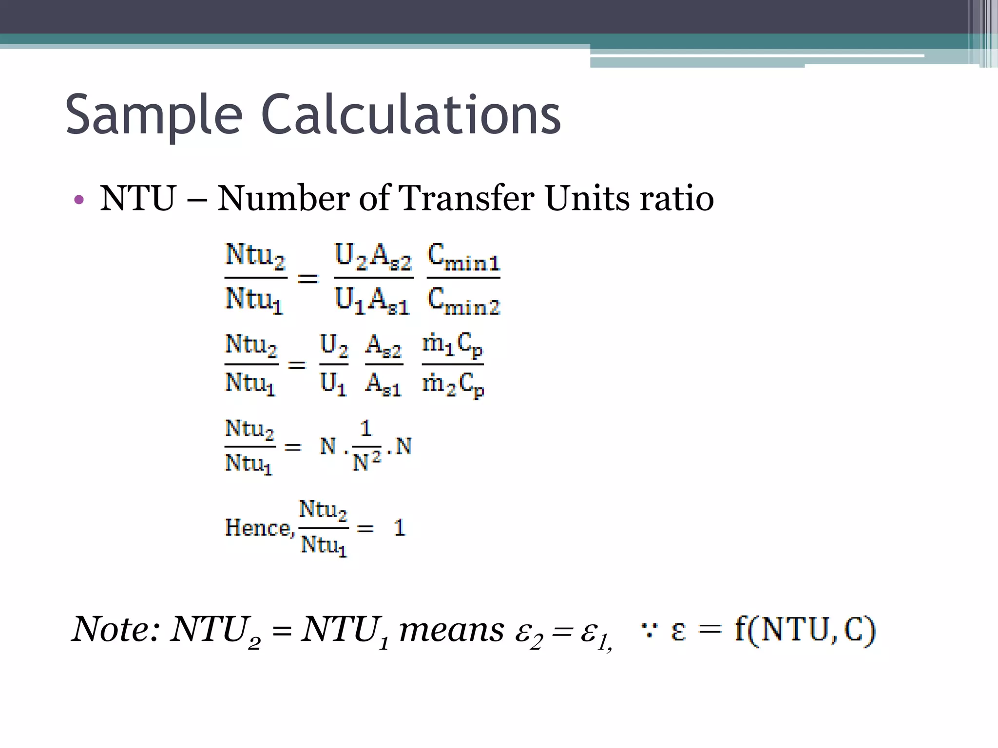

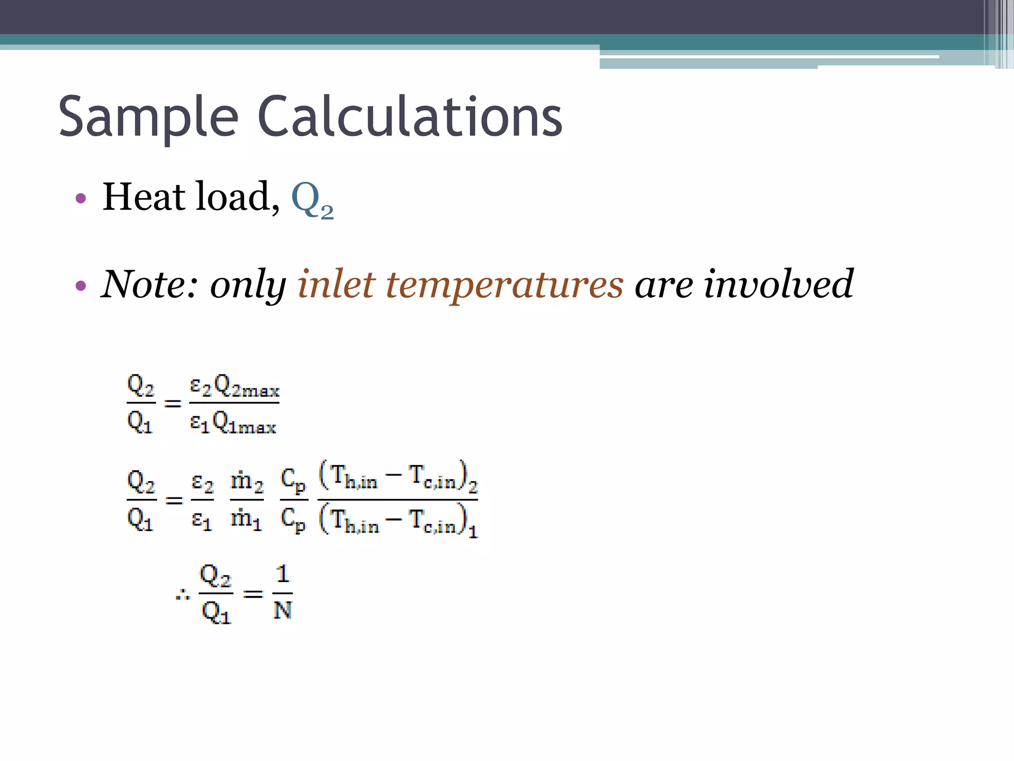
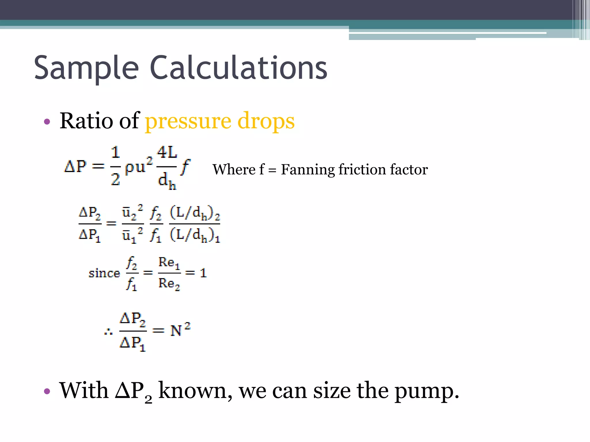
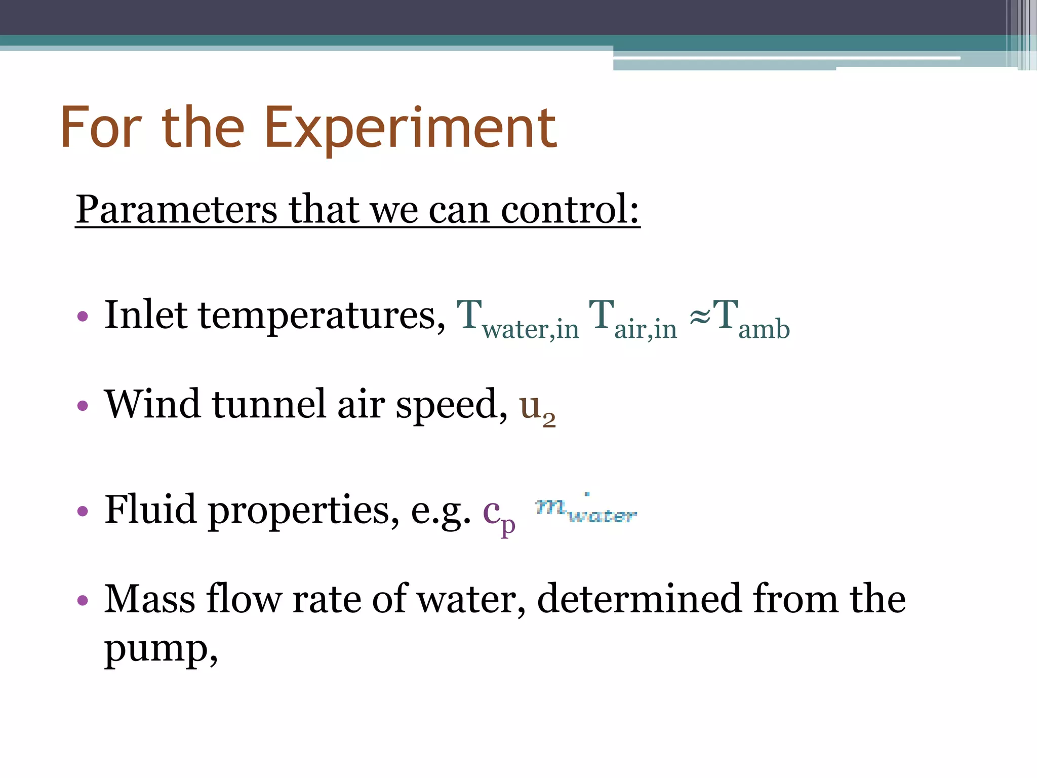
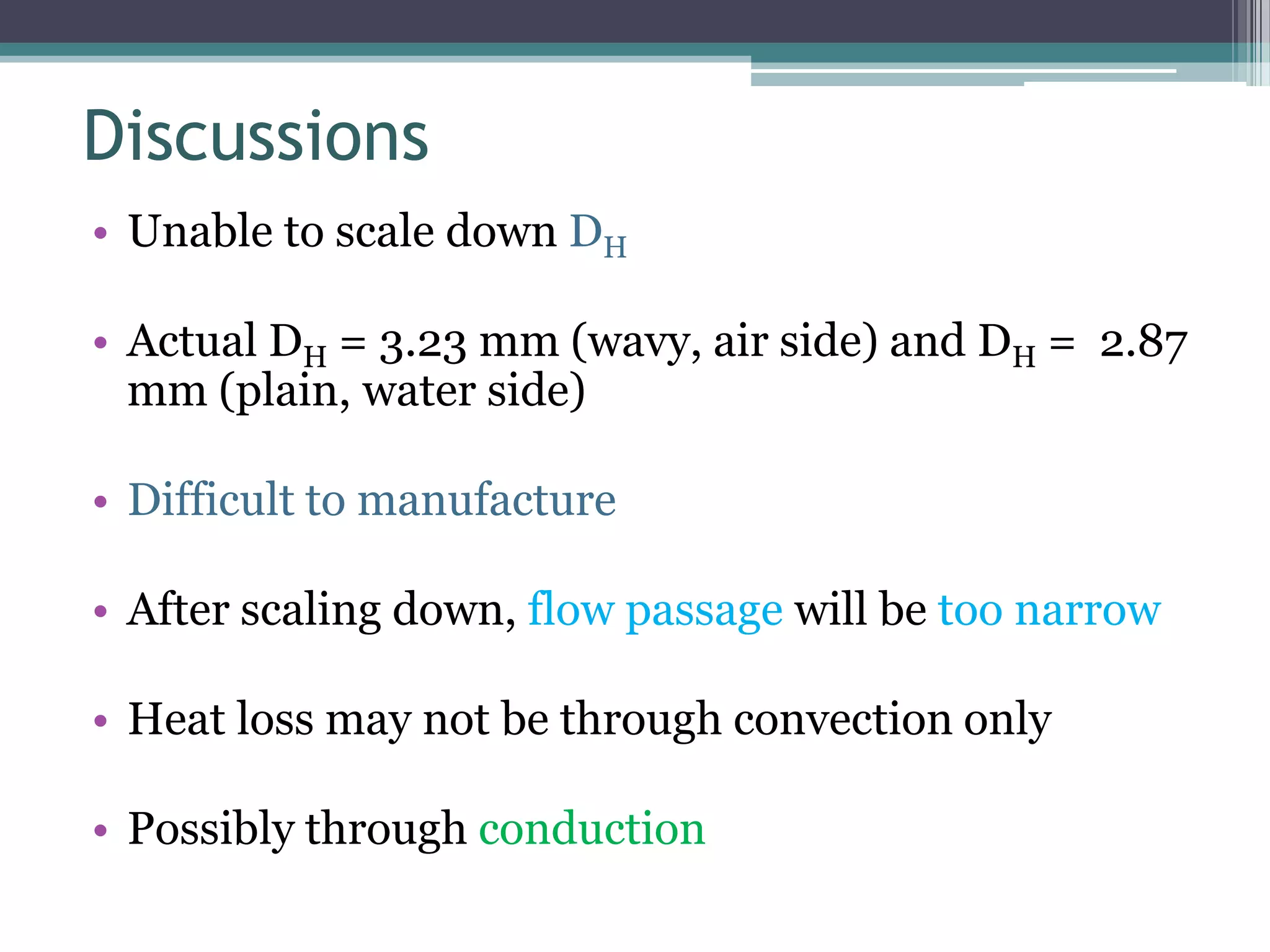
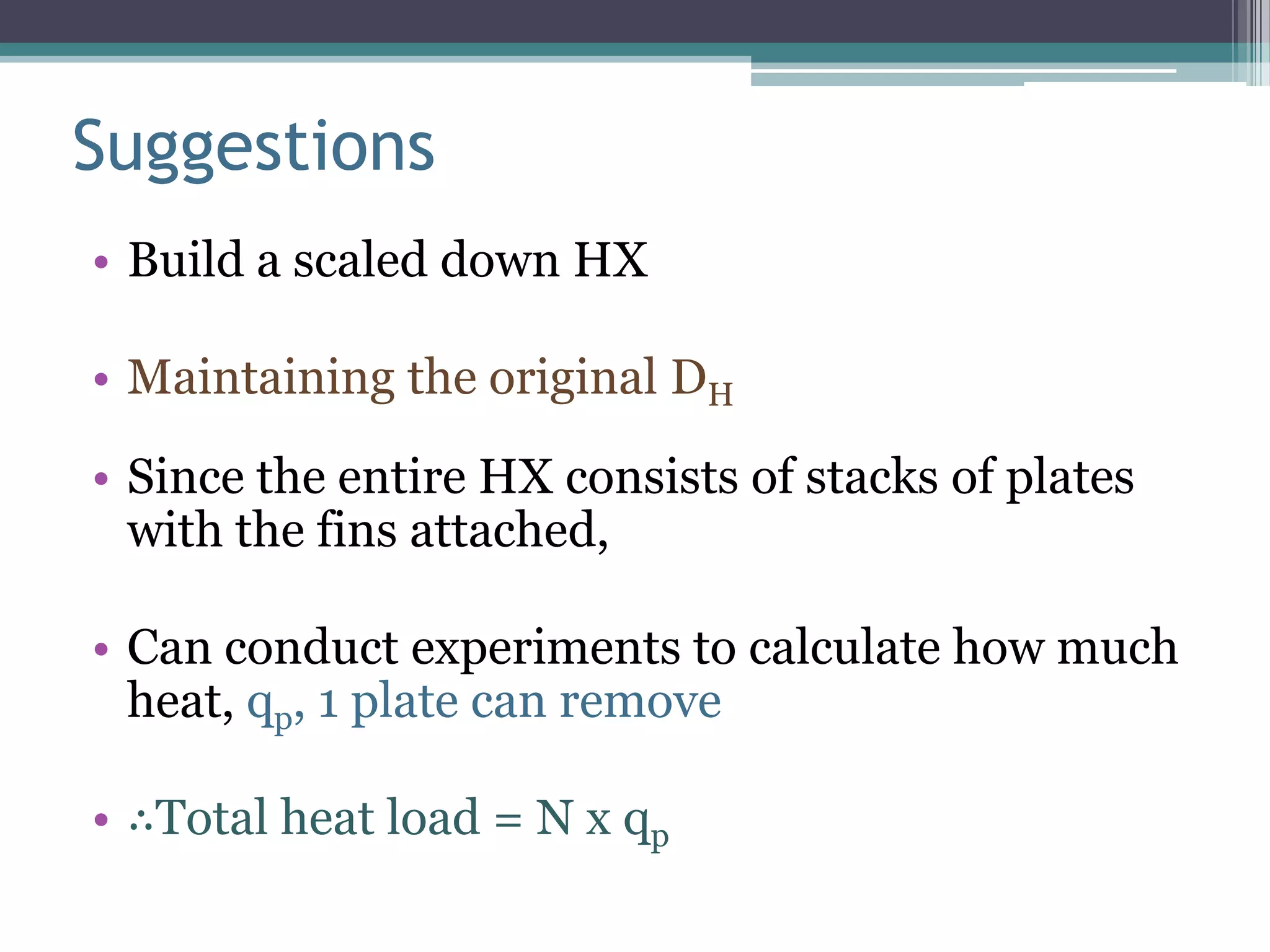
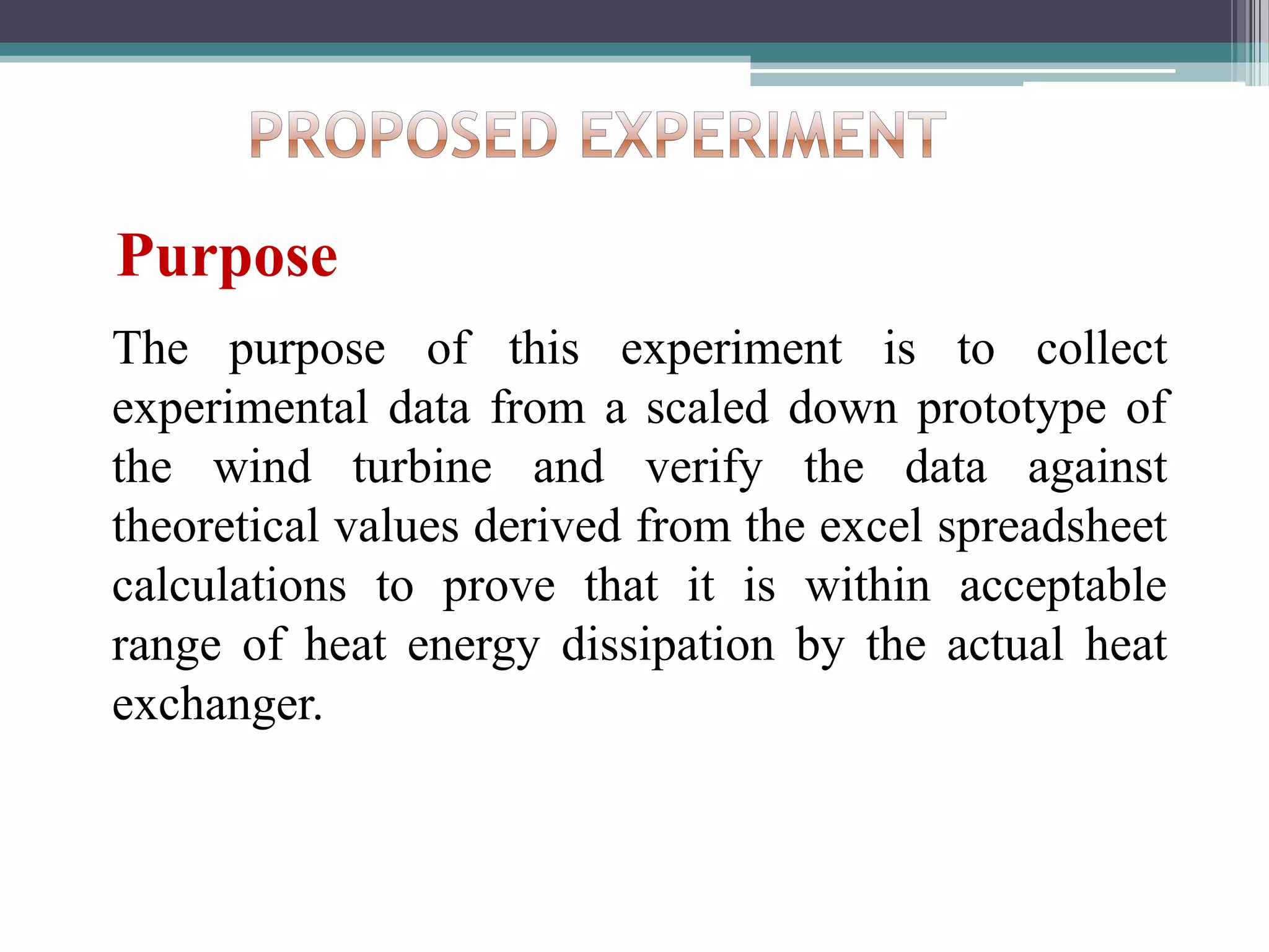
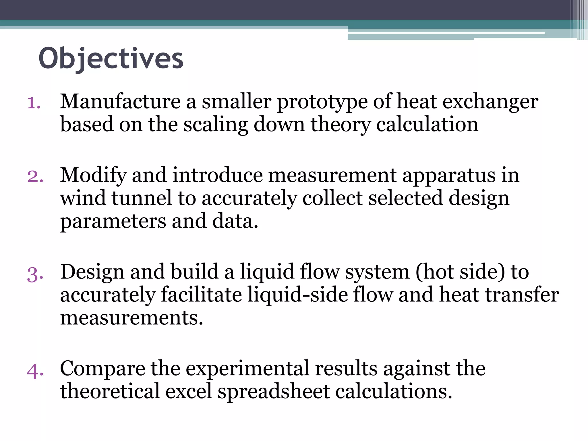
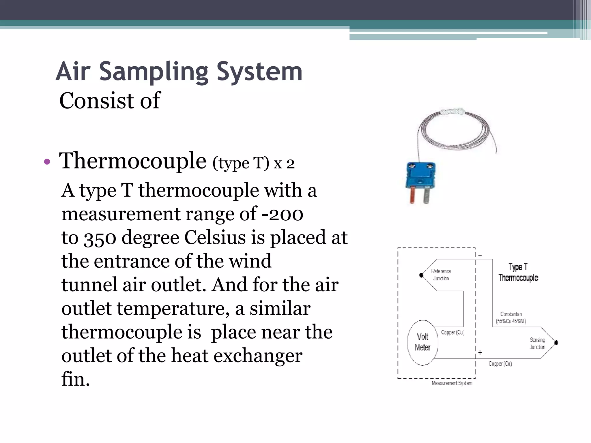
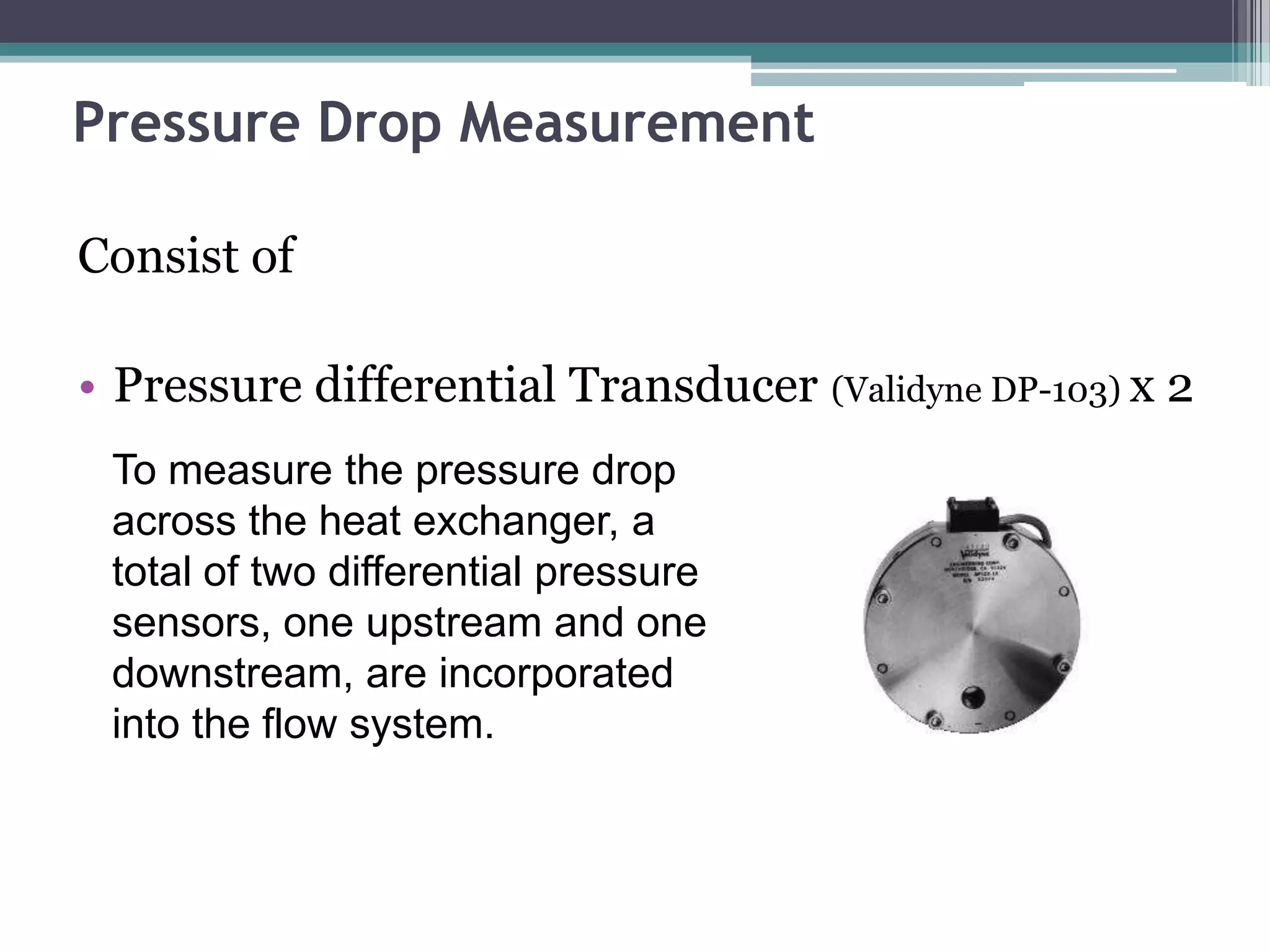
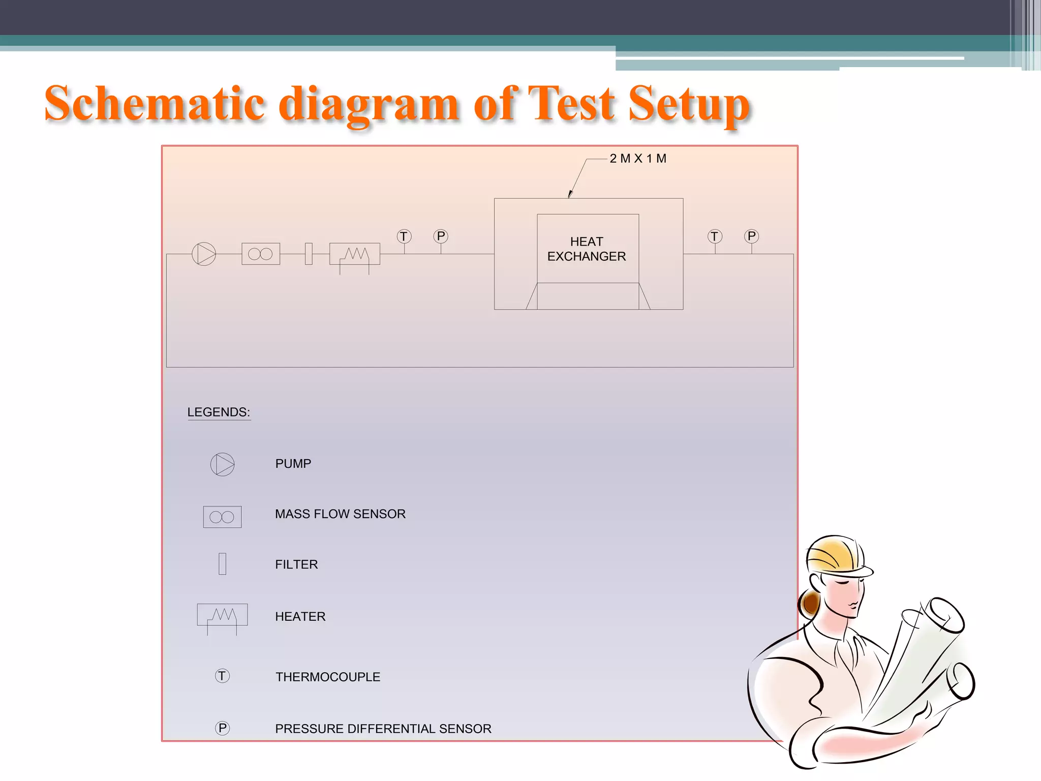
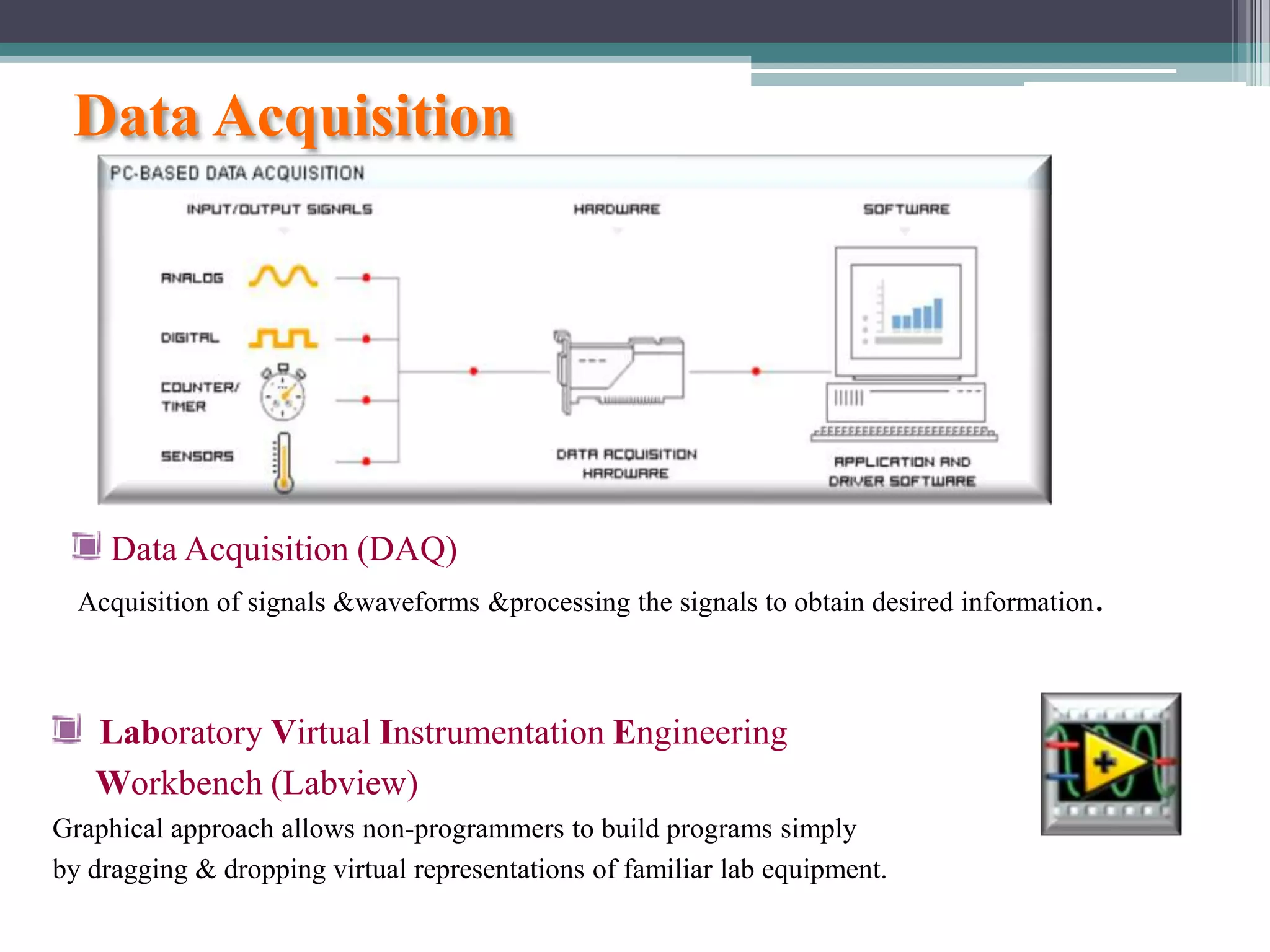
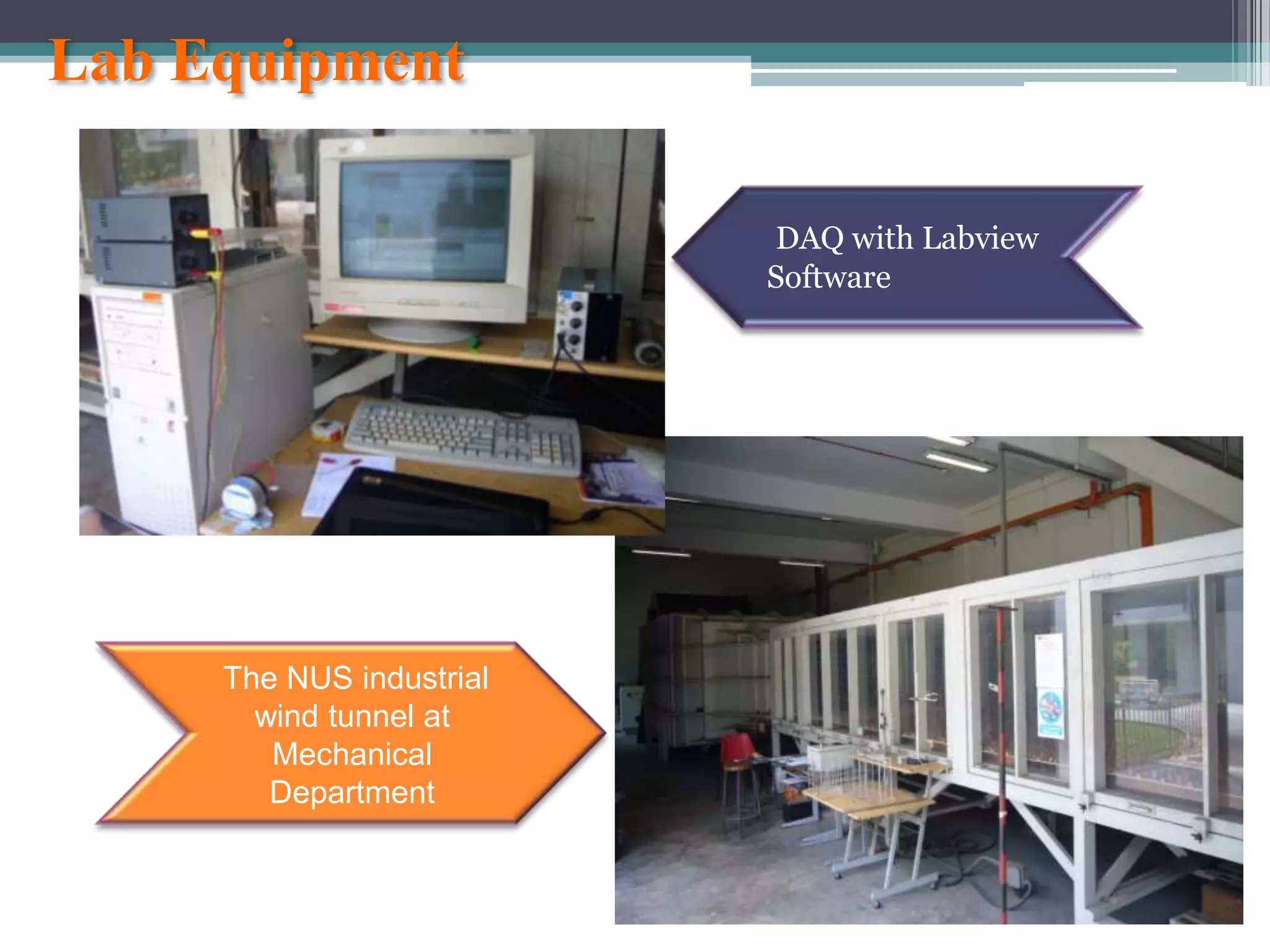
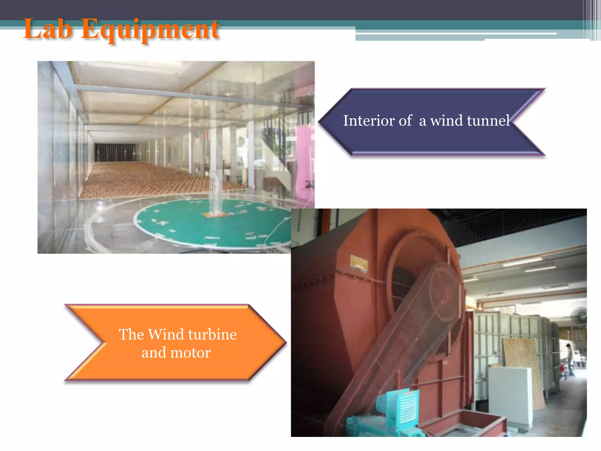


The document describes a proposed experiment to test a scaled-down prototype of a heat exchanger for wind turbines. The experiment aims to verify theoretical calculations by collecting experimental data on parameters like temperature, pressure, and heat transfer. A liquid flow system and air sampling system will circulate water and air through the prototype to measure performance and compare results to predictions. The experiment objectives are to manufacture and test the prototype, modify a wind tunnel for measurements, design a liquid flow circuit, and compare experimental and theoretical values.