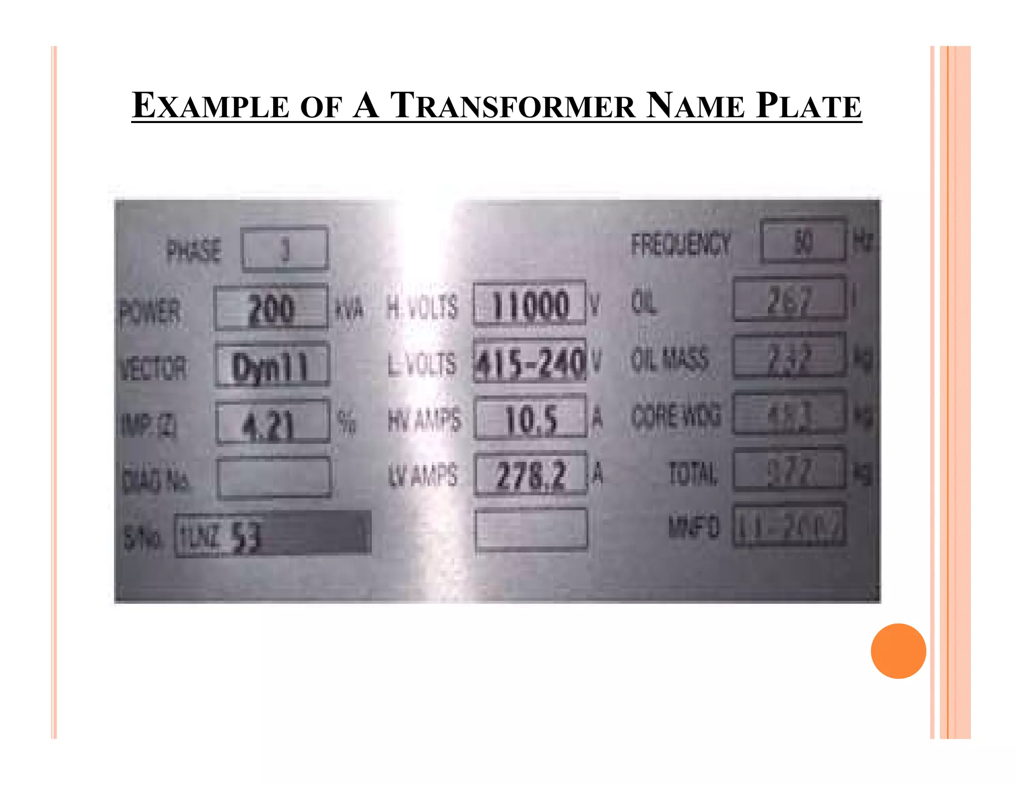
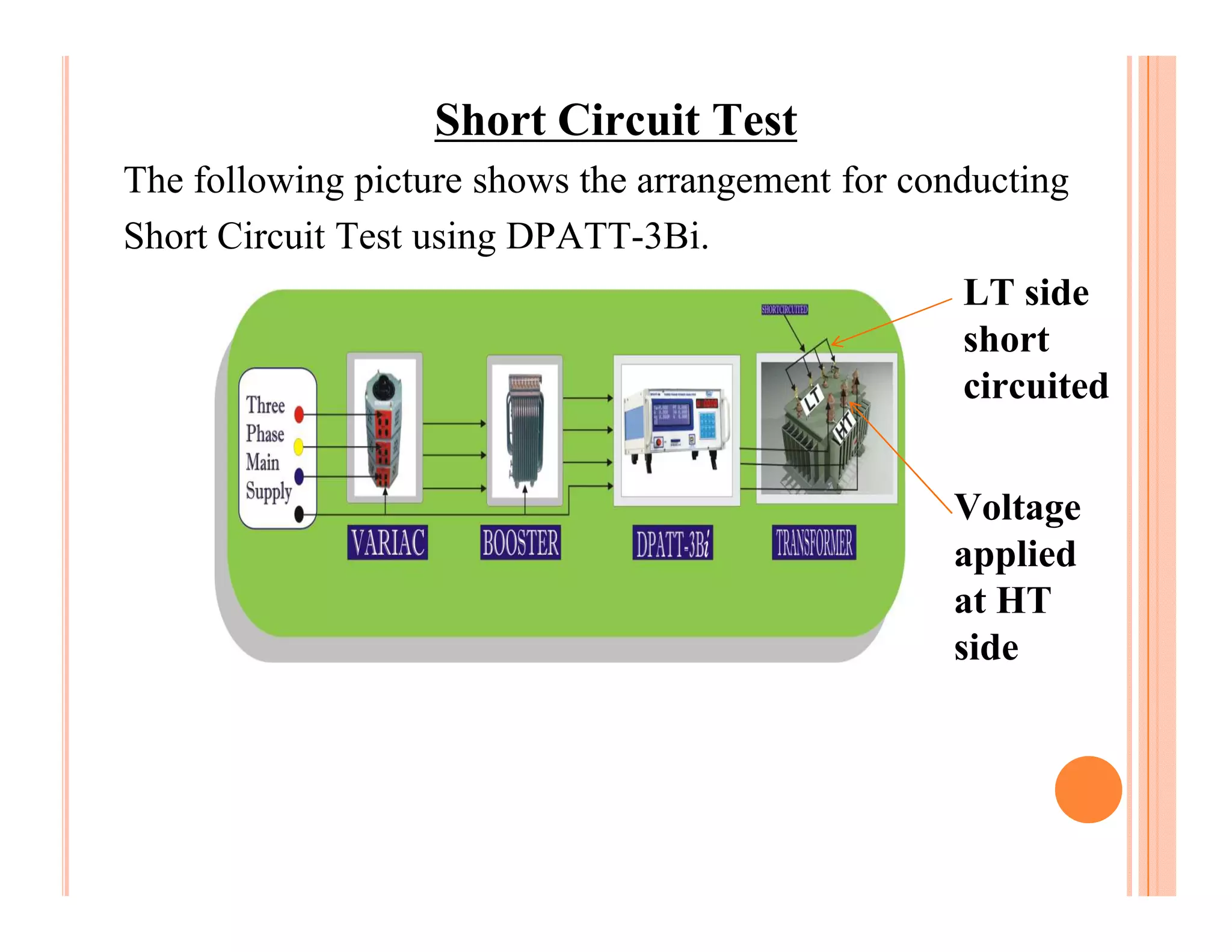
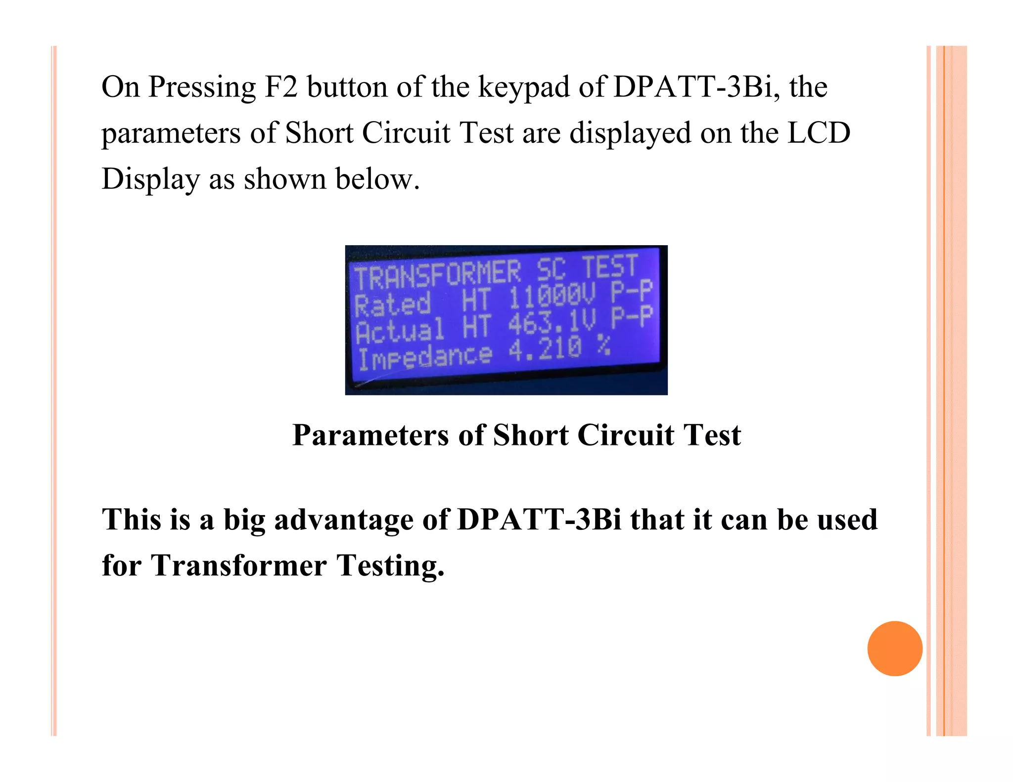
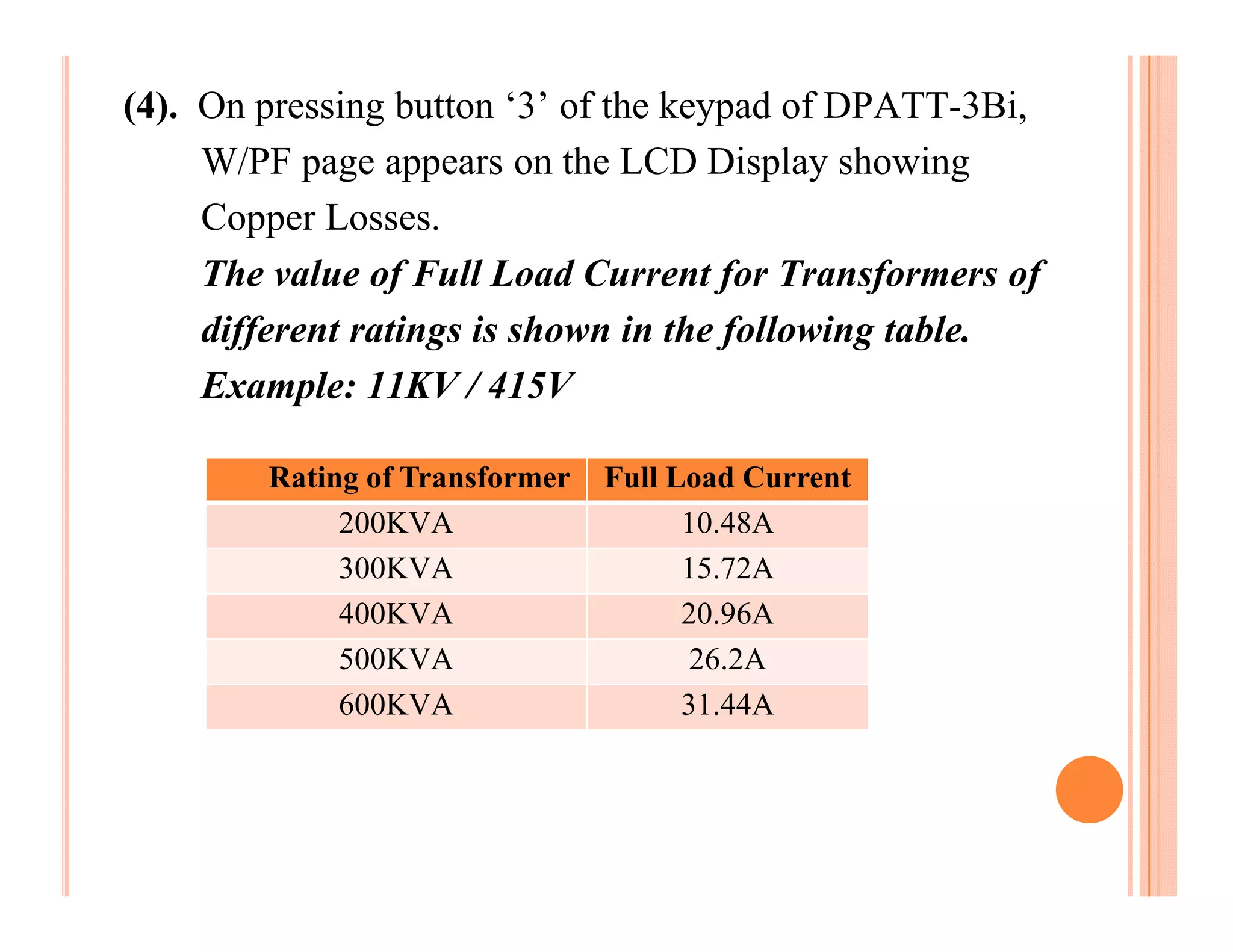
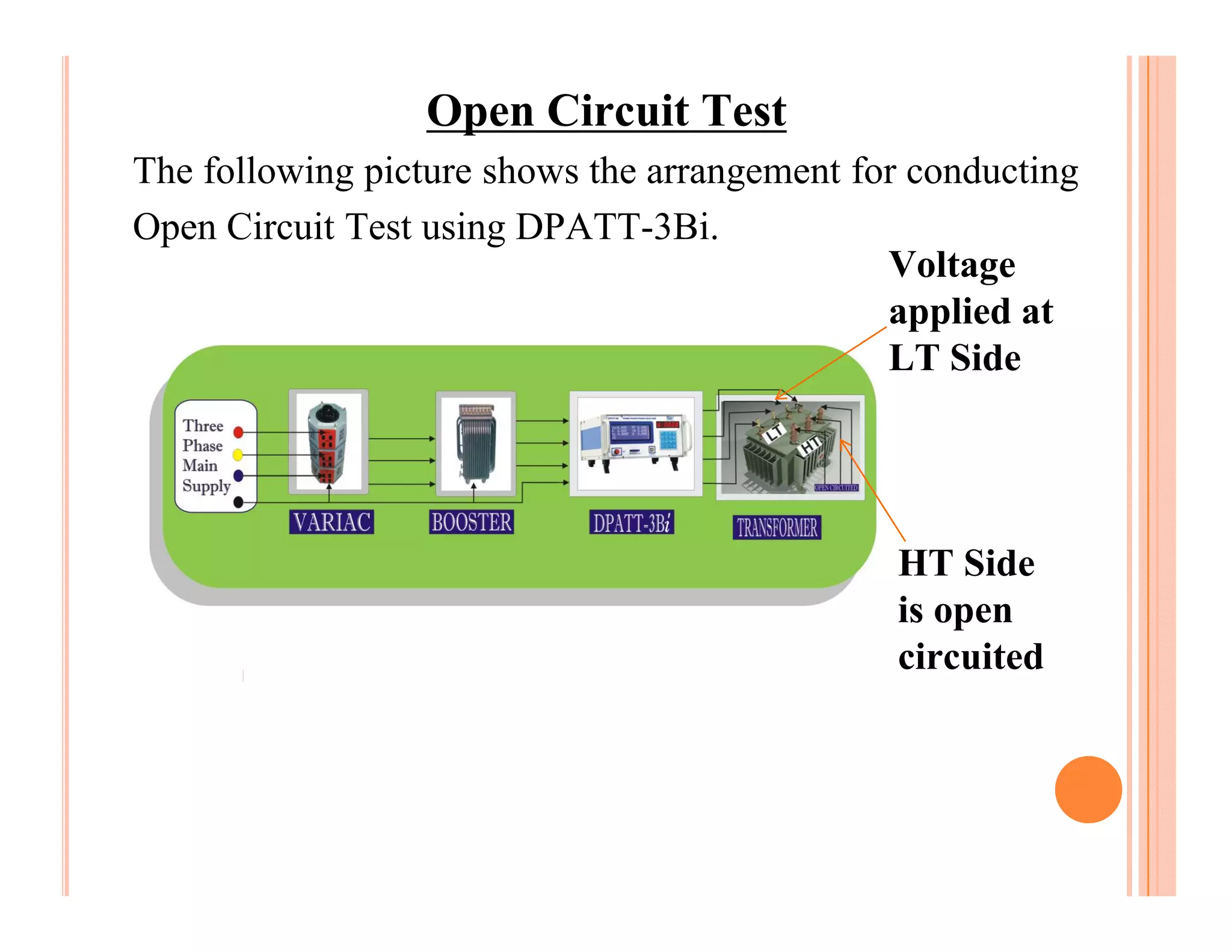
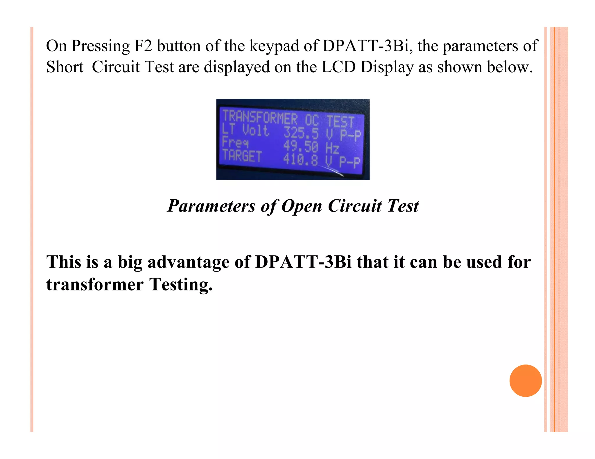
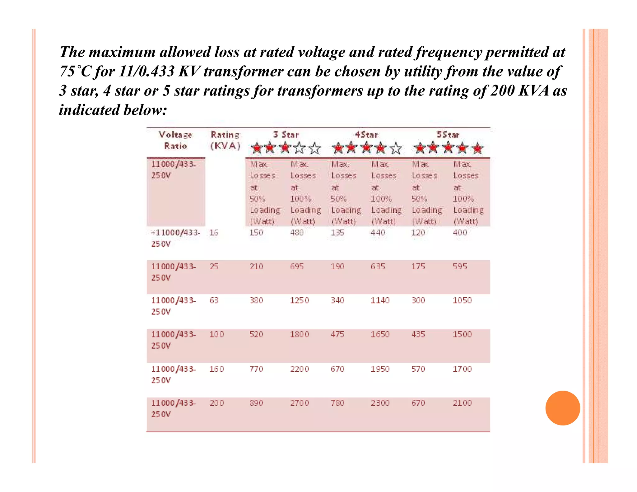
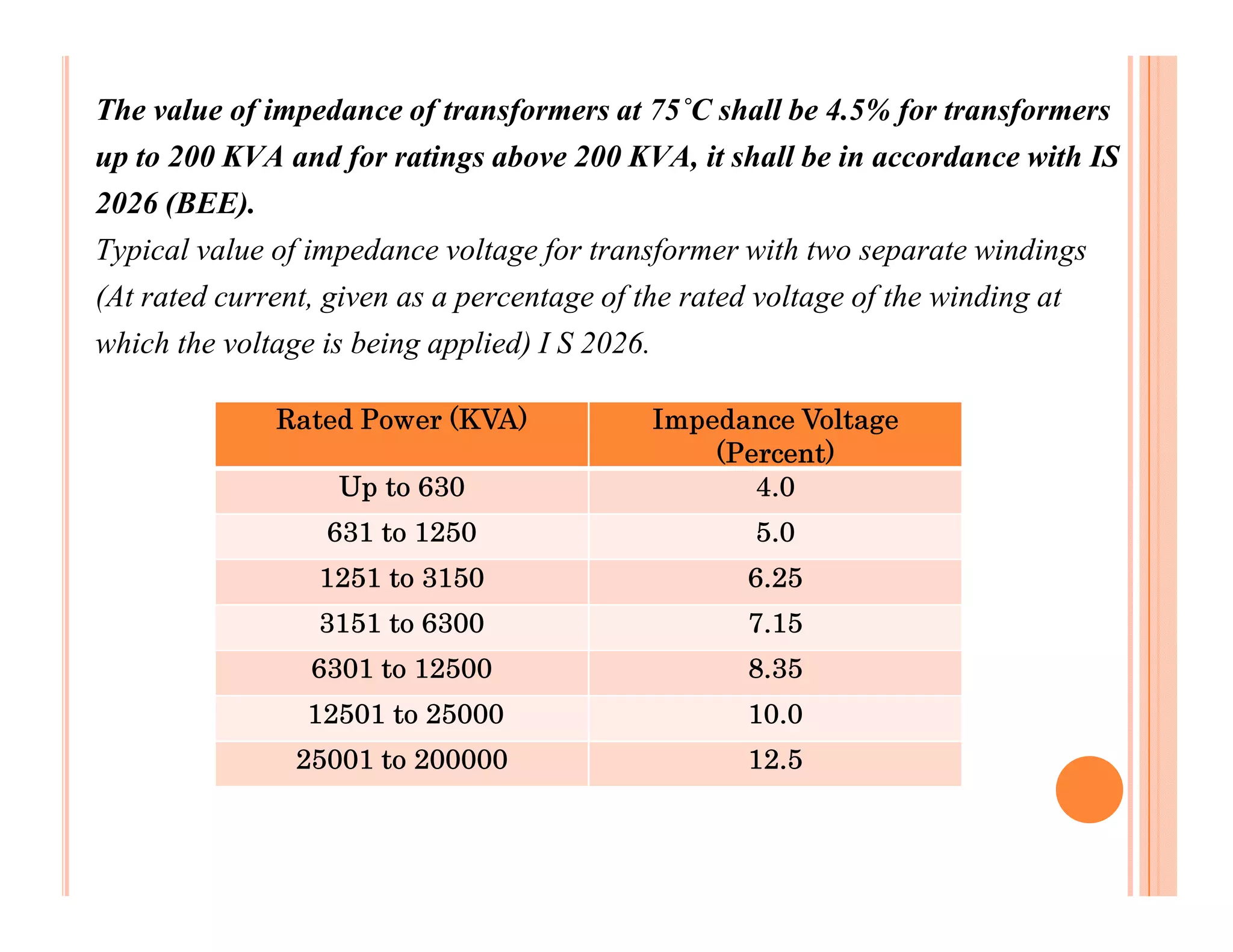
A
  Presentation On
Transformer Testing
 (Using DPATT-3Bi)
Losses of Transformers
The transformers are made of 2 types of materials: Iron and
Copper. The core of a transformer is made of Iron whereas the
winding which is wrapped over the iron core is made up of
Copper.


                        =                           +

     Transformer                    Iron Core           Copper Winding


Correspondingly there are 2 types of losses: Iron Loss and Copper Loss. Iron
and Copper losses are measured by open circuit and short circuit tests.
TESTS OF DISTRIBUTION TRANSFORMERS
Two tests are conducted for testing transformers. These tests are
known by different names as described in the table below.
       Short Circuit Test          Open Circuit Test

              OR                        OR

        Full Load Test            No Load Test

              OR                        OR

        Copper Loss Test          Iron Loss Test

              OR                        OR

       Winding Loss Test          Core Loss Test
EXAMPLE OF A TRANSFORMER NAME PLATE
Short Circuit Test
The following picture shows the arrangement for conducting
Short Circuit Test using DPATT-3Bi.
                                                    LT side
                                                    short
                                                    circuited


                                                   Voltage
                                                   applied
                                                   at HT
                                                   side
This test is conducted on the High Voltage side (HV Side)
of the Transformer.
The Secondary Winding (usually Low Voltage Side) of the
Transformer is short circuited.
Full load current is applied on the primary side of the
transformer.
The core losses are very small because applied voltage is
only few percentages of nominal voltage and hence can be
neglected.
Therefore the wattmeter measures only full load copper
loss.
Steps for conducting Short Circuit Test:
(1). Calculate Full Load Current from parameters
     available in Transformer’s name plate as described
     below.
     Transformer Rating:
     HT Voltage = 11KV
     LT Voltage = 415V (P-P)
     KVA Rating = 200 KVA


      Full Load Current = 10.49A
(2). Short circuit LT side and apply voltage at HT side of
     transformer until the full load current is achieved.
(3). Now calculate Impedance Voltage (the voltage at which
     full load current is achieved) and then calculate
     % Impedance as per the following formula.

     % Impedance = (Impedance Voltage / Rated Voltage) * 100


    Suppose the Full Load Current, 10.49A is obtained at 463.1V therefore the
    Impedance Voltage is 463.1V.
    % Impedance = (Impedance Voltage / Rated Voltage) * 100
                = (463.1 * 100) / 11000
                = 4.21
On Pressing F2 button of the keypad of DPATT-3Bi, the
parameters of Short Circuit Test are displayed on the LCD
Display as shown below.


              Parameters of Short Circuit Test

This is a big advantage of DPATT-3Bi that it can be used
for Transformer Testing.
(4). On pressing button ‘3’ of the keypad of DPATT-3Bi,
     W/PF page appears on the LCD Display showing
     Copper Losses.
     The value of Full Load Current for Transformers of
     different ratings is shown in the following table.
     Example: 11KV / 415V

        Rating of Transformer   Full Load Current
             200KVA                   10.48A
             300KVA                   15.72A
             400KVA                   20.96A
             500KVA                    26.2A
             600KVA                   31.44A
Open Circuit Test
The following picture shows the arrangement for conducting
Open Circuit Test using DPATT-3Bi.
                                              Voltage
                                              applied at
                                              LT Side


                                              HT Side
                                              is open
                                              circuited
o   Open circuit test is carried out to determine Iron Loss in
    Transformers.
o   Transformers dissipate Electrical Energy whenever they are
    On.
o   Core loss and magnetizing current depend upon applied
    voltage and frequency.
o   Since we have no control on variation of Mains Frequency
    therefore the applied voltage is varied to keep V/f ratio
    constant.
o   To minimize core loss, the design of Iron Core needs to be
    better.
Steps for conducting Open Circuit Test:

(1). Obtain the value of Rated Voltage from parameters given in
     transformer’s Name Plate as explained below.
    Example: According to transformer’s name plate
               HT Voltage = 11KV
               LT Voltage    = 415V (P-P)
               KVA Rating = 200 KVA
               Rated Voltage = 11KV (Primary Side)
               Rated Voltage = 415V (Secondary Side)
(2). Open circuit HT Side while apply voltage at LT Side
     through variac until the Rated Voltage is achieved.
Note: Incase supply frequency is different from rated frequency, the voltage
      to be applied is calculated as per supply frequency.
Illustration:
                    Rated LT Voltage       VRT = 415 V
                    Rated Frequency        FRT = 50 Hz
                    If, Supply frequency FS =49.50Hz
                    Voltage to be applied,
                     VA = (VRT / FRT ) * FS

                    VA = (415 / 50) * 49.50
                       = 410.85V
On Pressing F2 button of the keypad of DPATT-3Bi, the parameters of
Short Circuit Test are displayed on the LCD Display as shown below.


                Parameters of Open Circuit Test

This is a big advantage of DPATT-3Bi that it can be used for
transformer Testing.
(3). Calculate No Load Current as described below.
     Illustration:
     Transformer Rating
     HT Voltage= 11KV , Rated Voltage = 415V
     LT Voltage=415V , Full Load Current = 10.49A
     Rating of T/F= 200KVA
     According to BEE
    No Load Current = 2.5% of Full Load Current
                     = (10.49* 2.5 / 100)
    No Load Current = 0.26A

(4). On pressing ‘3’ button of keypad of DPATT-3Bi, W/PF
     Page appears on the LCD Display showing Iron Losses.
The maximum allowed loss at rated voltage and rated frequency permitted at
75˚C for 11/0.433 KV transformer can be chosen by utility from the value of
3 star, 4 star or 5 star ratings for transformers up to the rating of 200 KVA as
indicated below:
The value of impedance of transformers at 75˚C shall be 4.5% for transformers
up to 200 KVA and for ratings above 200 KVA, it shall be in accordance with IS
2026 (BEE).
Typical value of impedance voltage for transformer with two separate windings
(At rated current, given as a percentage of the rated voltage of the winding at
which the voltage is being applied) I S 2026.

             Rated Power (KVA)            Impedance Voltage
                                              (Percent)
                  Up to 630                      4.0
                 631 to 1250                      5.0
                 1251 to 3150                     6.25
                 3151 to 6300                     7.15
                6301 to 12500                     8.35
                12501 to 25000                    10.0
               25001 to 200000                    12.5
References:
(1). I S 2026-1977-Specification for Power Transformer.
(2). BEE CODE Transformer-2006
(3). Electrical Machines (J.B. Gupta)

Transformer testing

  • 1.
    A PresentationOn Transformer Testing (Using DPATT-3Bi)
  • 2.
    Losses of Transformers Thetransformers are made of 2 types of materials: Iron and Copper. The core of a transformer is made of Iron whereas the winding which is wrapped over the iron core is made up of Copper. = + Transformer Iron Core Copper Winding Correspondingly there are 2 types of losses: Iron Loss and Copper Loss. Iron and Copper losses are measured by open circuit and short circuit tests.
  • 3.
    TESTS OF DISTRIBUTIONTRANSFORMERS Two tests are conducted for testing transformers. These tests are known by different names as described in the table below. Short Circuit Test Open Circuit Test OR OR Full Load Test No Load Test OR OR Copper Loss Test Iron Loss Test OR OR Winding Loss Test Core Loss Test
  • 4.
    EXAMPLE OF ATRANSFORMER NAME PLATE
  • 5.
    Short Circuit Test Thefollowing picture shows the arrangement for conducting Short Circuit Test using DPATT-3Bi. LT side short circuited Voltage applied at HT side
  • 6.
    This test isconducted on the High Voltage side (HV Side) of the Transformer. The Secondary Winding (usually Low Voltage Side) of the Transformer is short circuited. Full load current is applied on the primary side of the transformer. The core losses are very small because applied voltage is only few percentages of nominal voltage and hence can be neglected. Therefore the wattmeter measures only full load copper loss.
  • 7.
    Steps for conductingShort Circuit Test: (1). Calculate Full Load Current from parameters available in Transformer’s name plate as described below. Transformer Rating: HT Voltage = 11KV LT Voltage = 415V (P-P) KVA Rating = 200 KVA Full Load Current = 10.49A
  • 8.
    (2). Short circuitLT side and apply voltage at HT side of transformer until the full load current is achieved. (3). Now calculate Impedance Voltage (the voltage at which full load current is achieved) and then calculate % Impedance as per the following formula. % Impedance = (Impedance Voltage / Rated Voltage) * 100 Suppose the Full Load Current, 10.49A is obtained at 463.1V therefore the Impedance Voltage is 463.1V. % Impedance = (Impedance Voltage / Rated Voltage) * 100 = (463.1 * 100) / 11000 = 4.21
  • 9.
    On Pressing F2button of the keypad of DPATT-3Bi, the parameters of Short Circuit Test are displayed on the LCD Display as shown below. Parameters of Short Circuit Test This is a big advantage of DPATT-3Bi that it can be used for Transformer Testing.
  • 10.
    (4). On pressingbutton ‘3’ of the keypad of DPATT-3Bi, W/PF page appears on the LCD Display showing Copper Losses. The value of Full Load Current for Transformers of different ratings is shown in the following table. Example: 11KV / 415V Rating of Transformer Full Load Current 200KVA 10.48A 300KVA 15.72A 400KVA 20.96A 500KVA 26.2A 600KVA 31.44A
  • 11.
    Open Circuit Test Thefollowing picture shows the arrangement for conducting Open Circuit Test using DPATT-3Bi. Voltage applied at LT Side HT Side is open circuited
  • 12.
    o Open circuit test is carried out to determine Iron Loss in Transformers. o Transformers dissipate Electrical Energy whenever they are On. o Core loss and magnetizing current depend upon applied voltage and frequency. o Since we have no control on variation of Mains Frequency therefore the applied voltage is varied to keep V/f ratio constant. o To minimize core loss, the design of Iron Core needs to be better.
  • 13.
    Steps for conductingOpen Circuit Test: (1). Obtain the value of Rated Voltage from parameters given in transformer’s Name Plate as explained below. Example: According to transformer’s name plate HT Voltage = 11KV LT Voltage = 415V (P-P) KVA Rating = 200 KVA Rated Voltage = 11KV (Primary Side) Rated Voltage = 415V (Secondary Side)
  • 14.
    (2). Open circuitHT Side while apply voltage at LT Side through variac until the Rated Voltage is achieved. Note: Incase supply frequency is different from rated frequency, the voltage to be applied is calculated as per supply frequency. Illustration: Rated LT Voltage VRT = 415 V Rated Frequency FRT = 50 Hz If, Supply frequency FS =49.50Hz Voltage to be applied, VA = (VRT / FRT ) * FS VA = (415 / 50) * 49.50 = 410.85V
  • 15.
    On Pressing F2button of the keypad of DPATT-3Bi, the parameters of Short Circuit Test are displayed on the LCD Display as shown below. Parameters of Open Circuit Test This is a big advantage of DPATT-3Bi that it can be used for transformer Testing.
  • 16.
    (3). Calculate NoLoad Current as described below. Illustration: Transformer Rating HT Voltage= 11KV , Rated Voltage = 415V LT Voltage=415V , Full Load Current = 10.49A Rating of T/F= 200KVA According to BEE No Load Current = 2.5% of Full Load Current = (10.49* 2.5 / 100) No Load Current = 0.26A (4). On pressing ‘3’ button of keypad of DPATT-3Bi, W/PF Page appears on the LCD Display showing Iron Losses.
  • 17.
    The maximum allowedloss at rated voltage and rated frequency permitted at 75˚C for 11/0.433 KV transformer can be chosen by utility from the value of 3 star, 4 star or 5 star ratings for transformers up to the rating of 200 KVA as indicated below:
  • 18.
    The value ofimpedance of transformers at 75˚C shall be 4.5% for transformers up to 200 KVA and for ratings above 200 KVA, it shall be in accordance with IS 2026 (BEE). Typical value of impedance voltage for transformer with two separate windings (At rated current, given as a percentage of the rated voltage of the winding at which the voltage is being applied) I S 2026. Rated Power (KVA) Impedance Voltage (Percent) Up to 630 4.0 631 to 1250 5.0 1251 to 3150 6.25 3151 to 6300 7.15 6301 to 12500 8.35 12501 to 25000 10.0 25001 to 200000 12.5
  • 19.
    References: (1). I S2026-1977-Specification for Power Transformer. (2). BEE CODE Transformer-2006 (3). Electrical Machines (J.B. Gupta)