The document provides a comprehensive overview of engineering drawing, covering essential topics such as drawing standards, types of lines, lettering, dimensioning, and traditional drawing tools. It outlines the importance of adhering to recognized standards (like IS and ISO) for clarity and uniformity in technical drawings. Additionally, it details drawing sheet specifications, folding methods, and the methods of dimensioning, emphasizing legibility and accuracy.
INTRODUCTION
An Engineering Drawingis a type of technical drawing,
used to fully and clearly define requirements for
engineered items, and is usually created in accordance
with standardized conventions for layout, nomenclature
interpretation, appearance size etc.
4
https://in.linkedin.com/in/rishabhnatholia
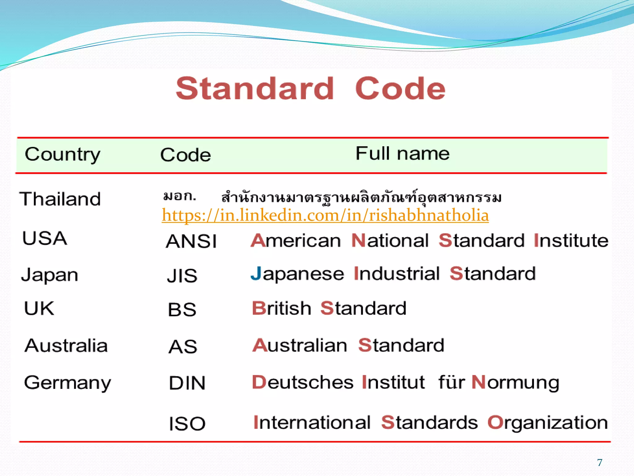
DRAWING STANDARD
Standardare the set of rules that govern how technical drawing are
represented.
Drawing Standard are used so that drawing convey the same meaning to
everyone who reads them.
Different countries use different standards according to there ease.
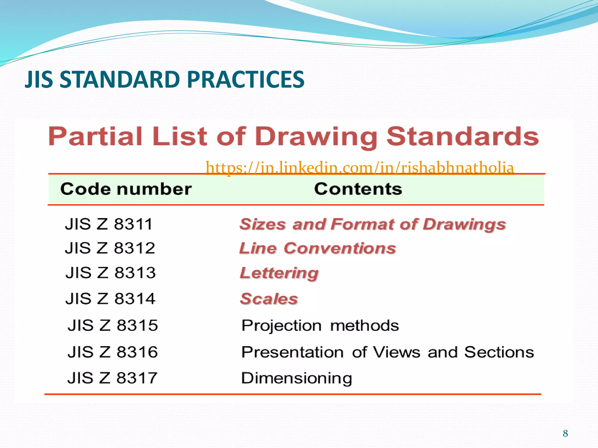
In India we follow IS (Indian Standard) which is some what like JIS system
IS: 1071 I-1983 Sizes of Drawing Sheet
IS: 9609 (Part 2)1985 Lettering on Technical Drawing
IS: 10713-1983 Scales on Drawing
6
https://in.linkedin.com/in/rishabhnatholia
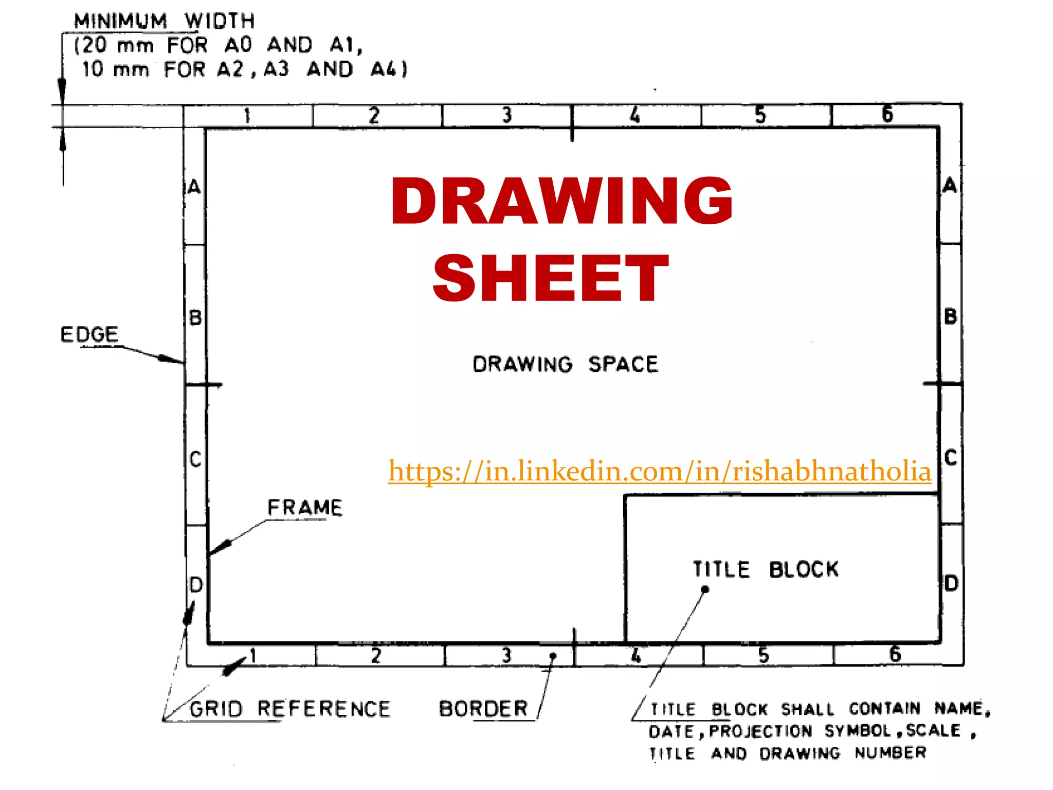
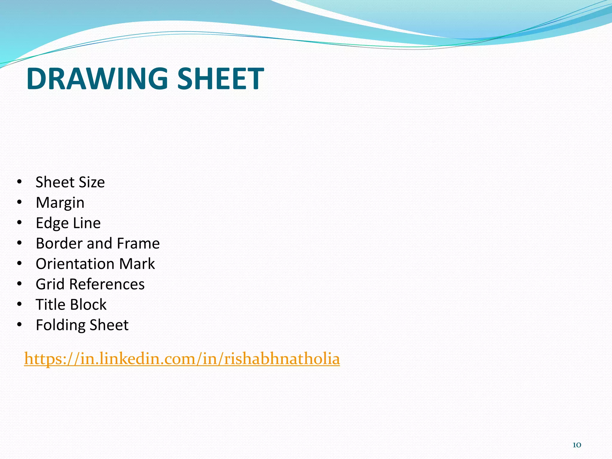
DRAWING SHEET
10
• SheetSize
• Margin
• Edge Line
• Border and Frame
• Orientation Mark
• Grid References
• Title Block
• Folding Sheet
https://in.linkedin.com/in/rishabhnatholia
11.
11
Example of DrawingSheet
Margin
Untrimmed Size
Trimmed Size
Margin Line
Orientation Mark
Title Block
Grid Reference
Frame
Border
https://in.linkedin.com/in/rishabhnatholia
12.
SHEET SIZE
12
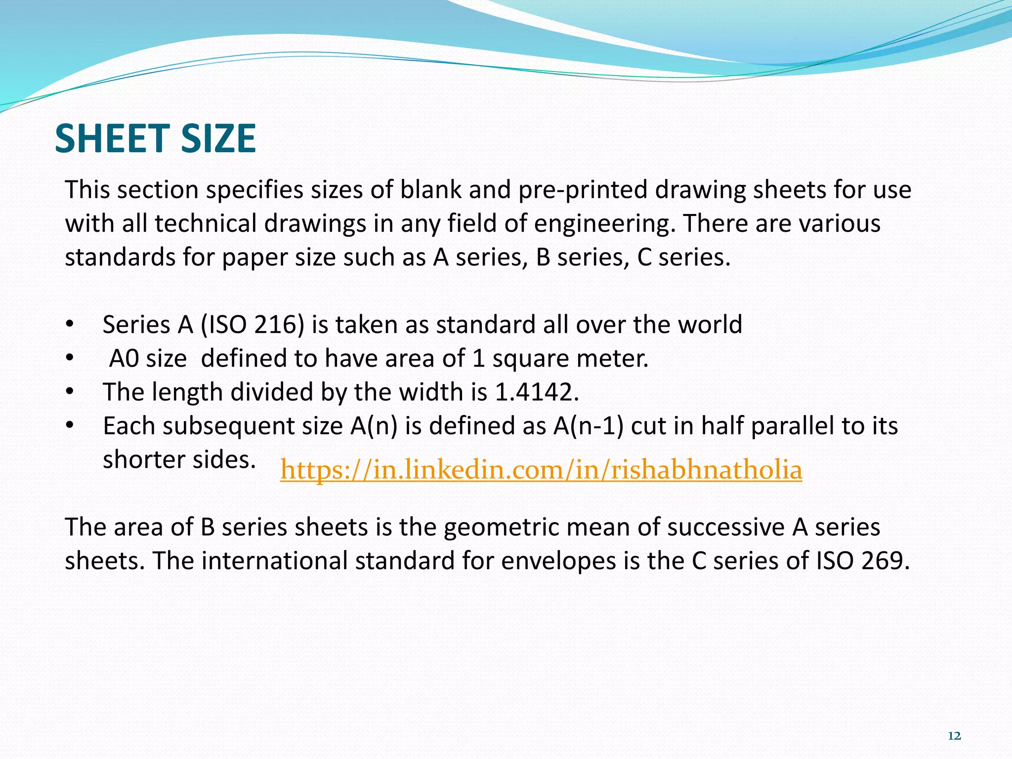
This sectionspecifies sizes of blank and pre-printed drawing sheets for use
with all technical drawings in any field of engineering. There are various
standards for paper size such as A series, B series, C series.
• Series A (ISO 216) is taken as standard all over the world
• A0 size defined to have area of 1 square meter.
• The length divided by the width is 1.4142.
• Each subsequent size A(n) is defined as A(n-1) cut in half parallel to its
shorter sides.
The area of B series sheets is the geometric mean of successive A series
sheets. The international standard for envelopes is the C series of ISO 269.
https://in.linkedin.com/in/rishabhnatholia
13.
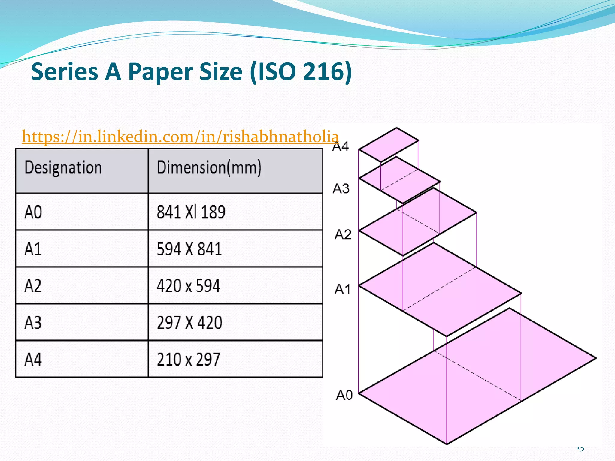
Series A PaperSize (ISO 216)
13
https://in.linkedin.com/in/rishabhnatholia
14.
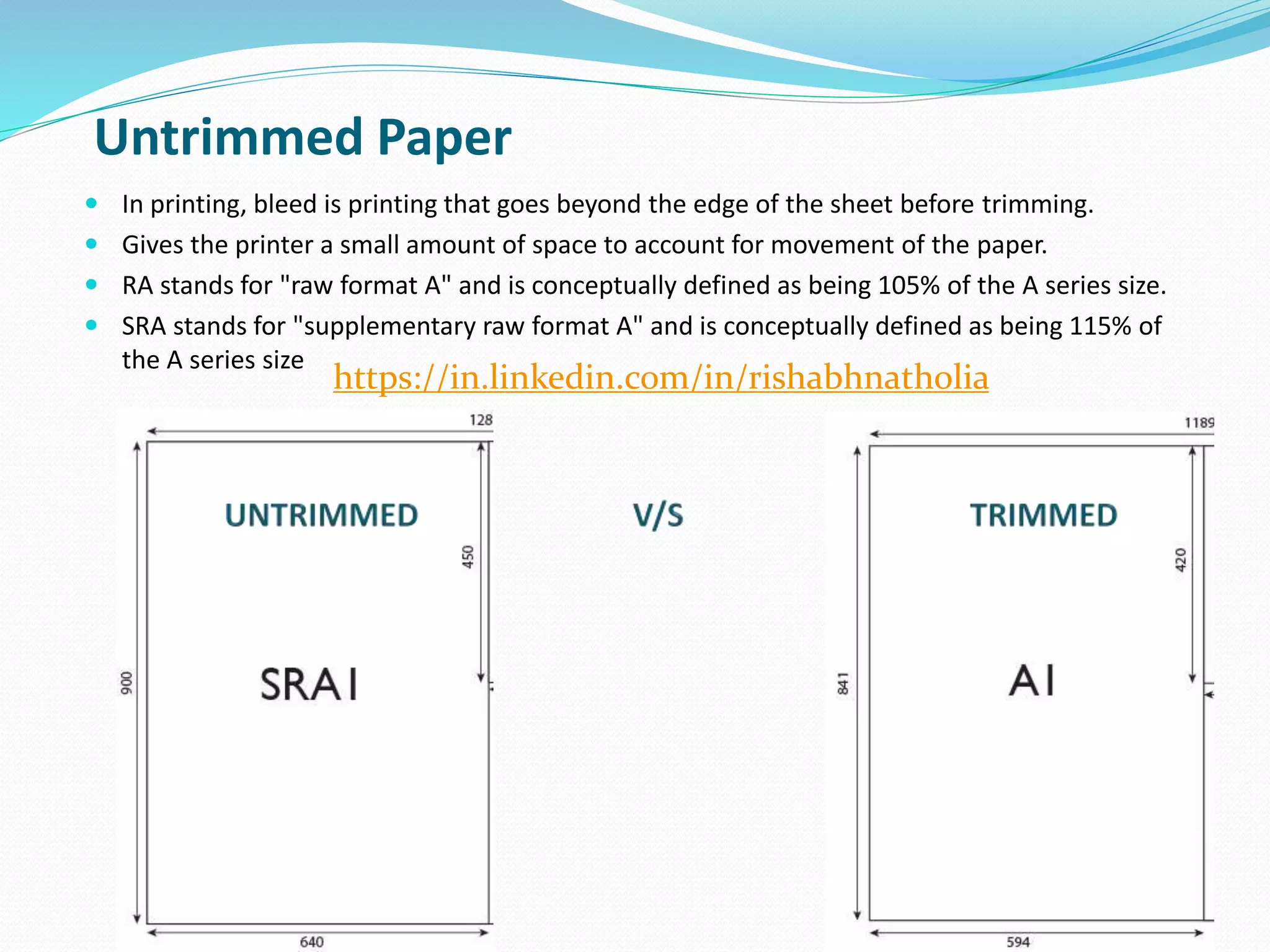
In printing,bleed is printing that goes beyond the edge of the sheet before trimming.
Gives the printer a small amount of space to account for movement of the paper.
RA stands for "raw format A" and is conceptually defined as being 105% of the A series size.
SRA stands for "supplementary raw format A" and is conceptually defined as being 115% of
the A series size
14
Untrimmed Paper
https://in.linkedin.com/in/rishabhnatholia
16
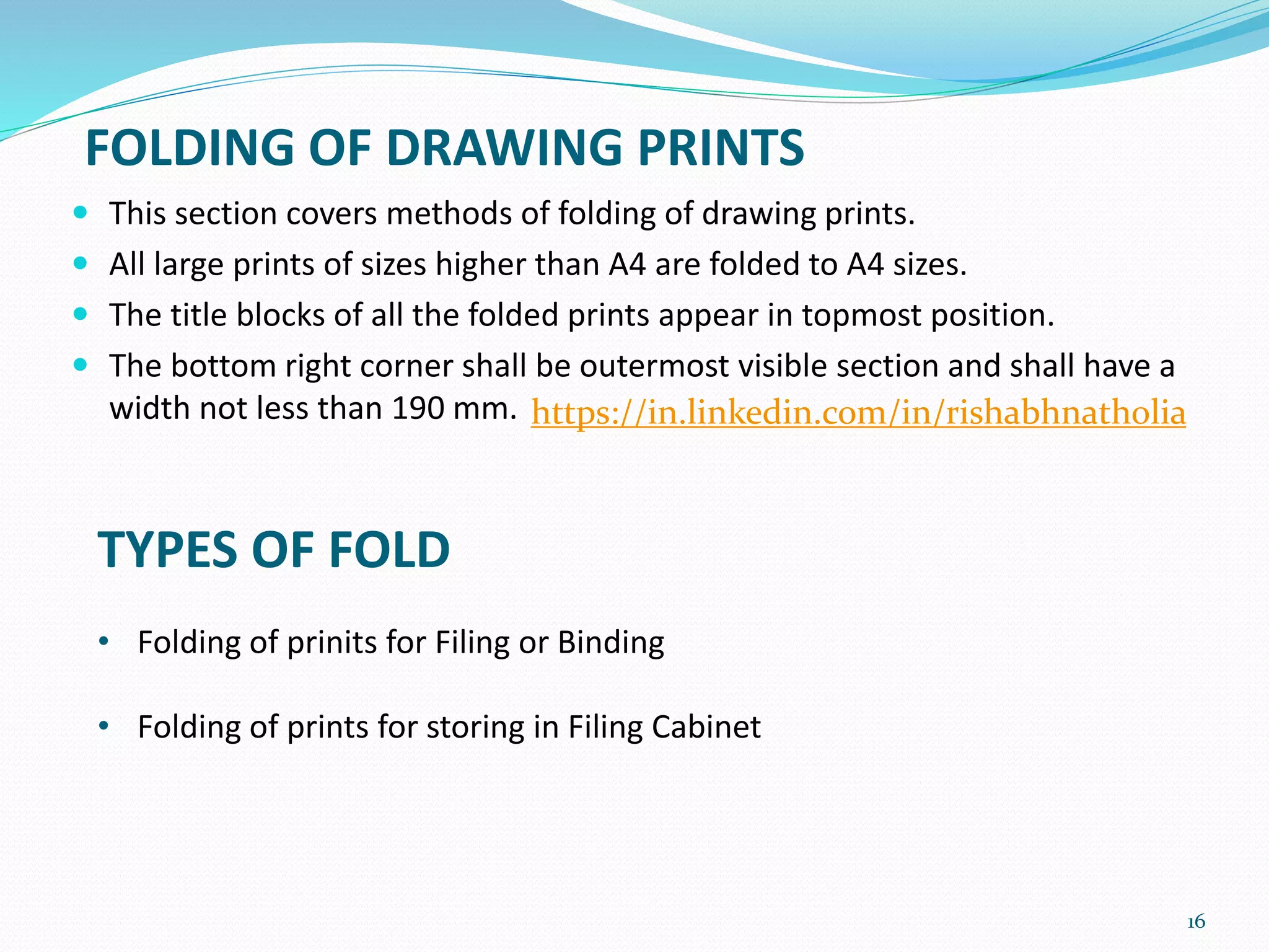
This sectioncovers methods of folding of drawing prints.
All large prints of sizes higher than A4 are folded to A4 sizes.
The title blocks of all the folded prints appear in topmost position.
The bottom right corner shall be outermost visible section and shall have a
width not less than 190 mm.
FOLDING OF DRAWING PRINTS
TYPES OF FOLD
• Folding of prinits for Filing or Binding
• Folding of prints for storing in Filing Cabinet
https://in.linkedin.com/in/rishabhnatholia
17.
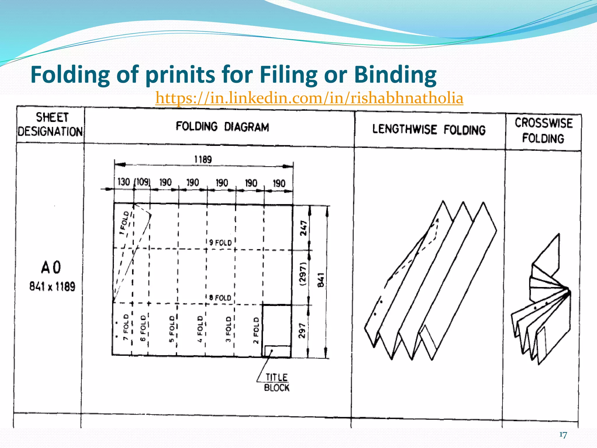
Folding of prinitsfor Filing or Binding
17
https://in.linkedin.com/in/rishabhnatholia
18.
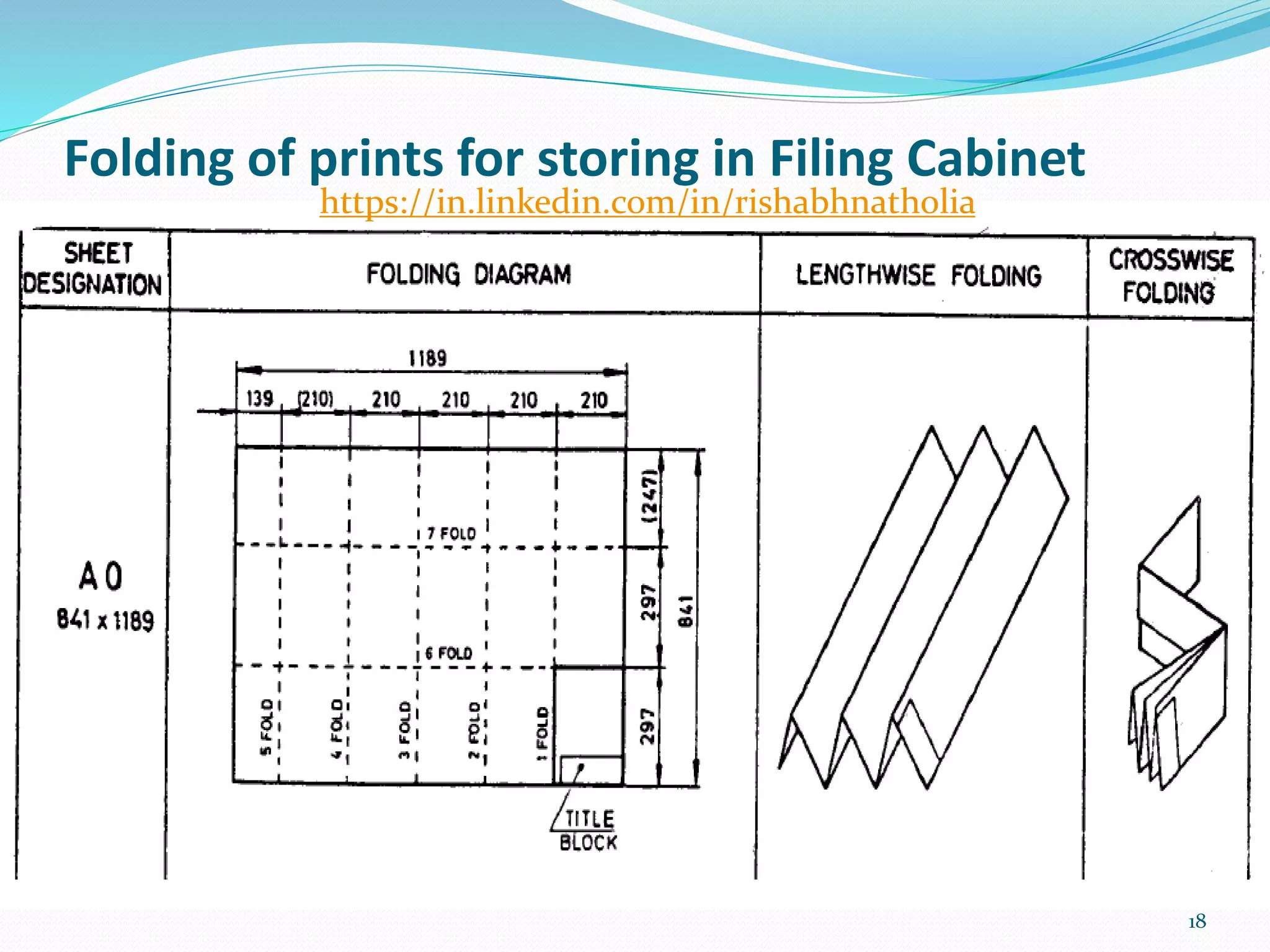
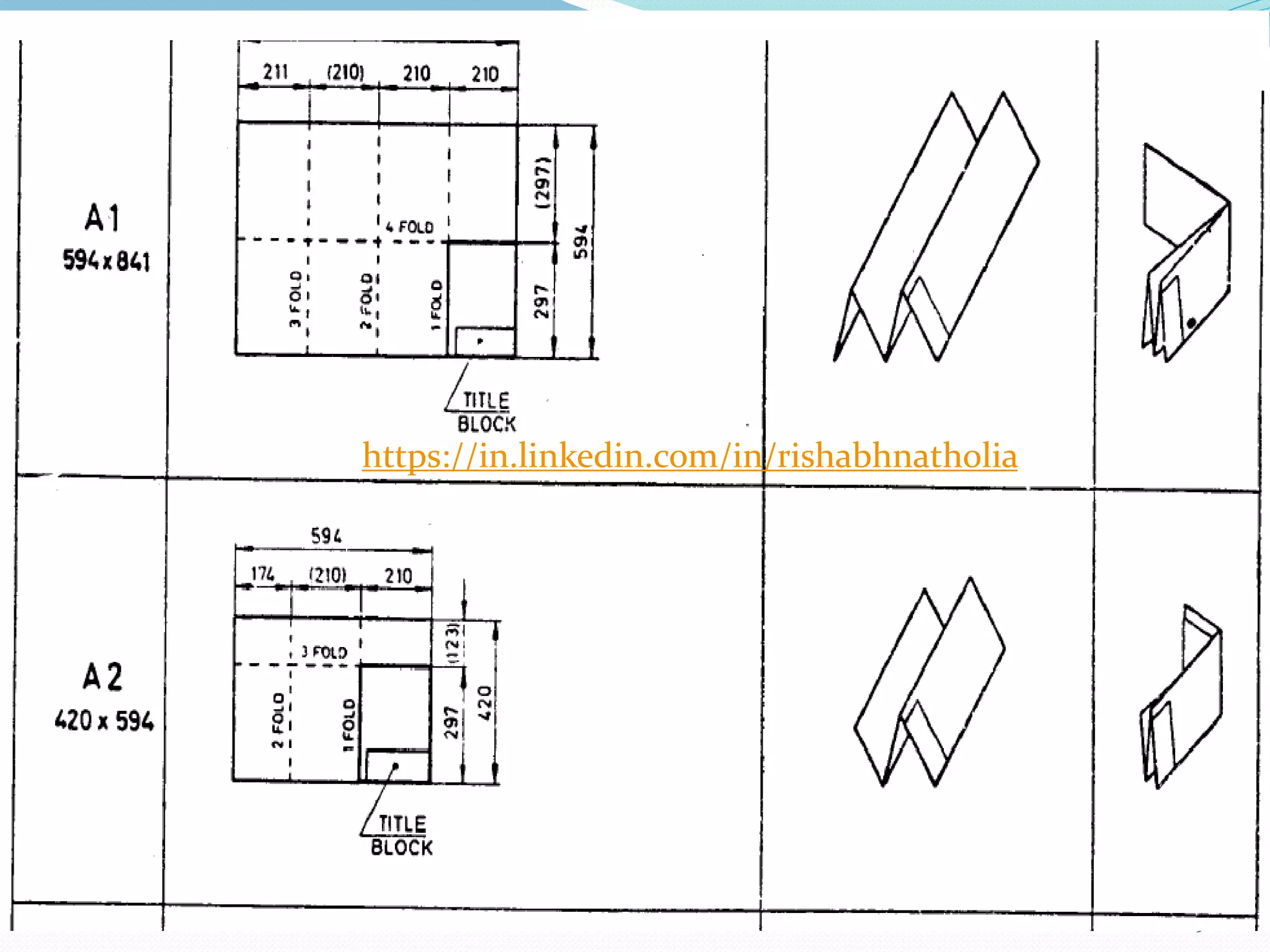
Folding of printsfor storing in Filing Cabinet
18
https://in.linkedin.com/in/rishabhnatholia
22
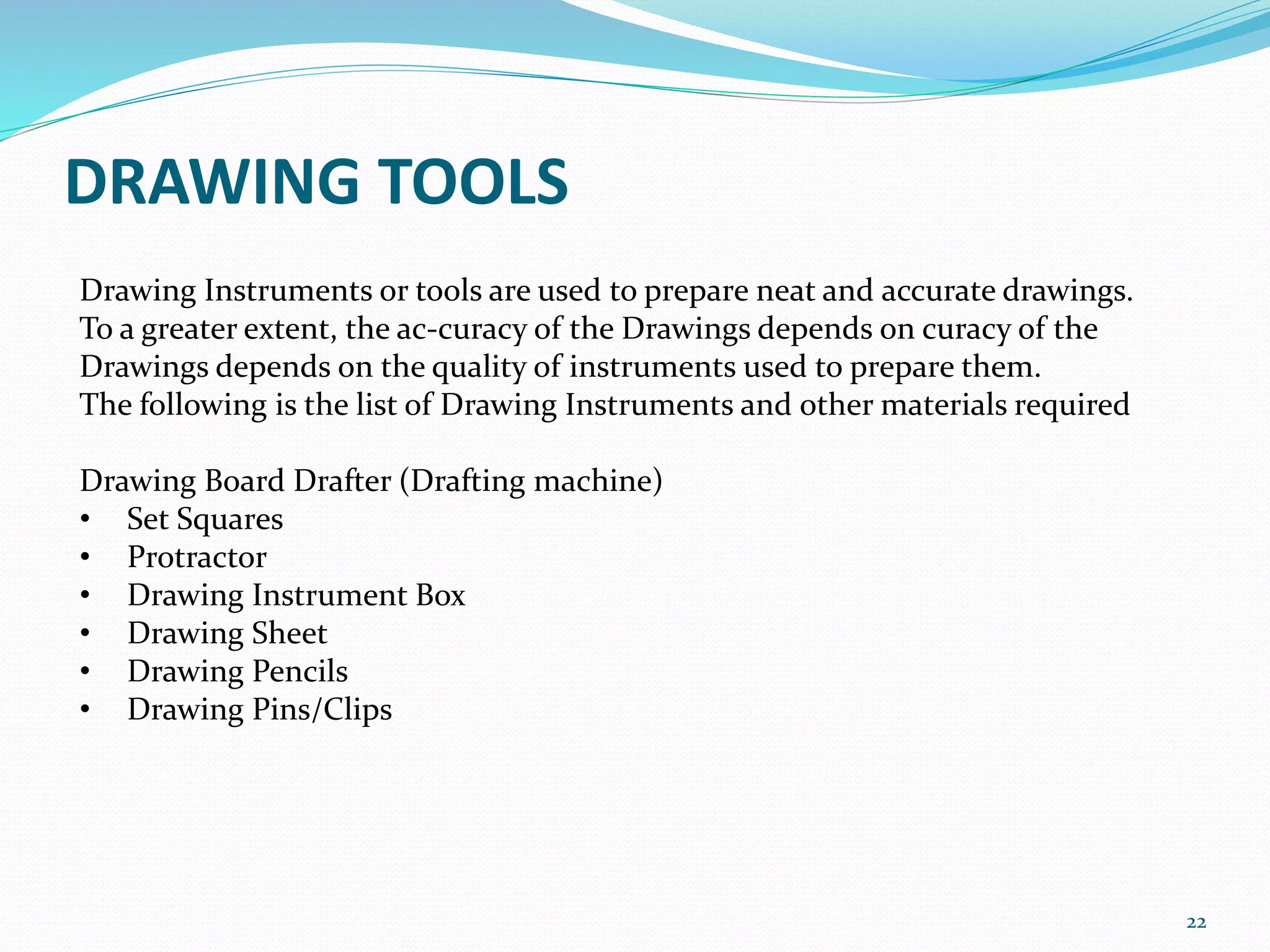
Drawing Instruments ortools are used to prepare neat and accurate drawings.
To a greater extent, the ac-curacy of the Drawings depends on curacy of the
Drawings depends on the quality of instruments used to prepare them.
The following is the list of Drawing Instruments and other materials required
Drawing Board Drafter (Drafting machine)
• Set Squares
• Protractor
• Drawing Instrument Box
• Drawing Sheet
• Drawing Pencils
• Drawing Pins/Clips
DRAWING TOOLS
23.
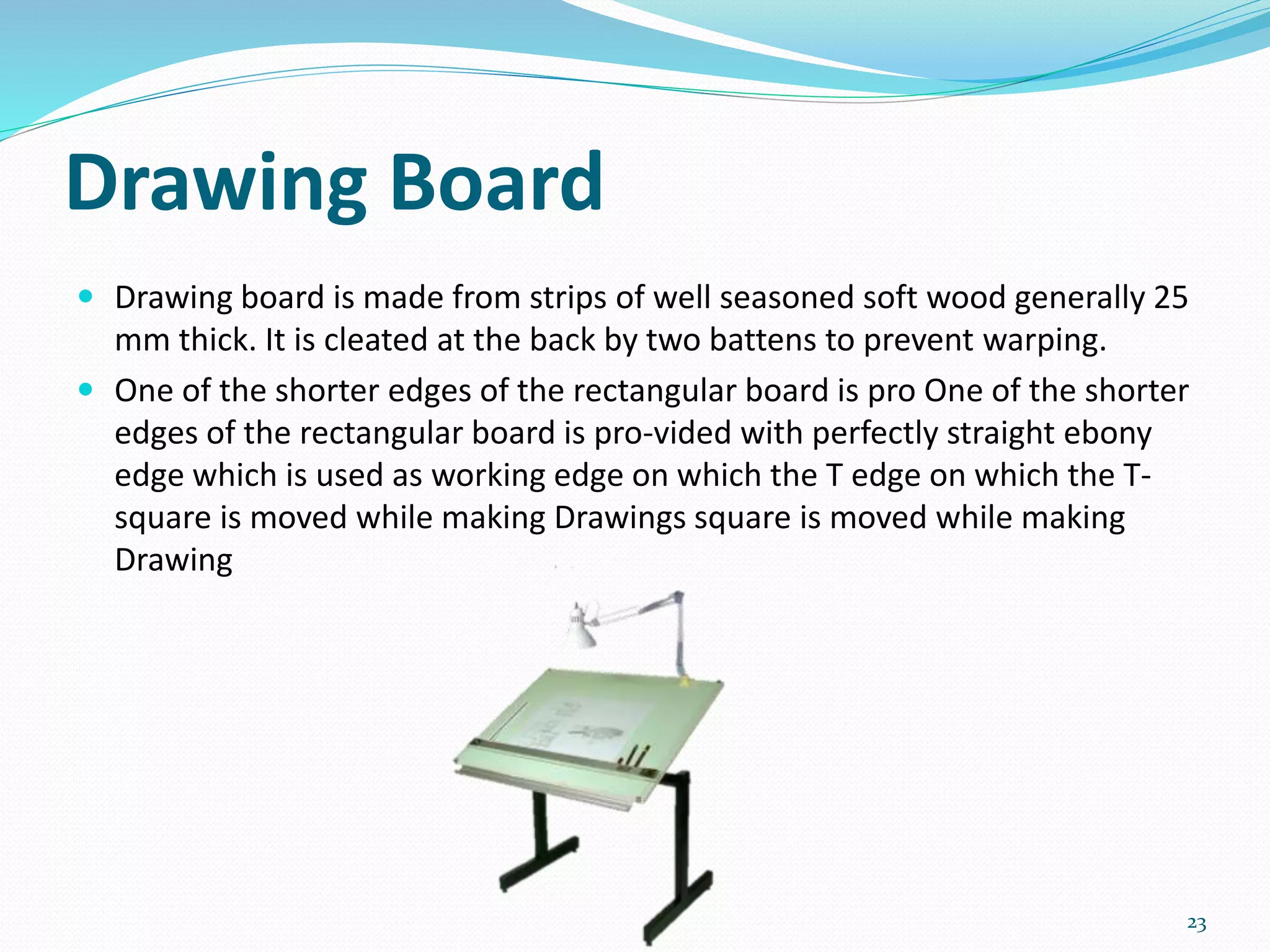
Drawing Board
Drawingboard is made from strips of well seasoned soft wood generally 25
mm thick. It is cleated at the back by two battens to prevent warping.
One of the shorter edges of the rectangular board is pro One of the shorter
edges of the rectangular board is pro-vided with perfectly straight ebony
edge which is used as working edge on which the T edge on which the T-
square is moved while making Drawings square is moved while making
Drawing
23
24.
PENCIL
24
https://in.linkedin.com/in/rishabhnatholia
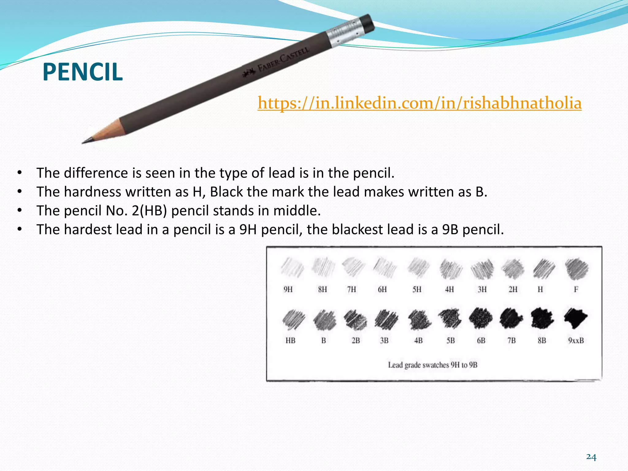
• The differenceis seen in the type of lead is in the pencil.
• The hardness written as H, Black the mark the lead makes written as B.
• The pencil No. 2(HB) pencil stands in middle.
• The hardest lead in a pencil is a 9H pencil, the blackest lead is a 9B pencil.
25.
25
TRY TO NAMETHESE
https://in.linkedin.com/in/rishabhnatholia
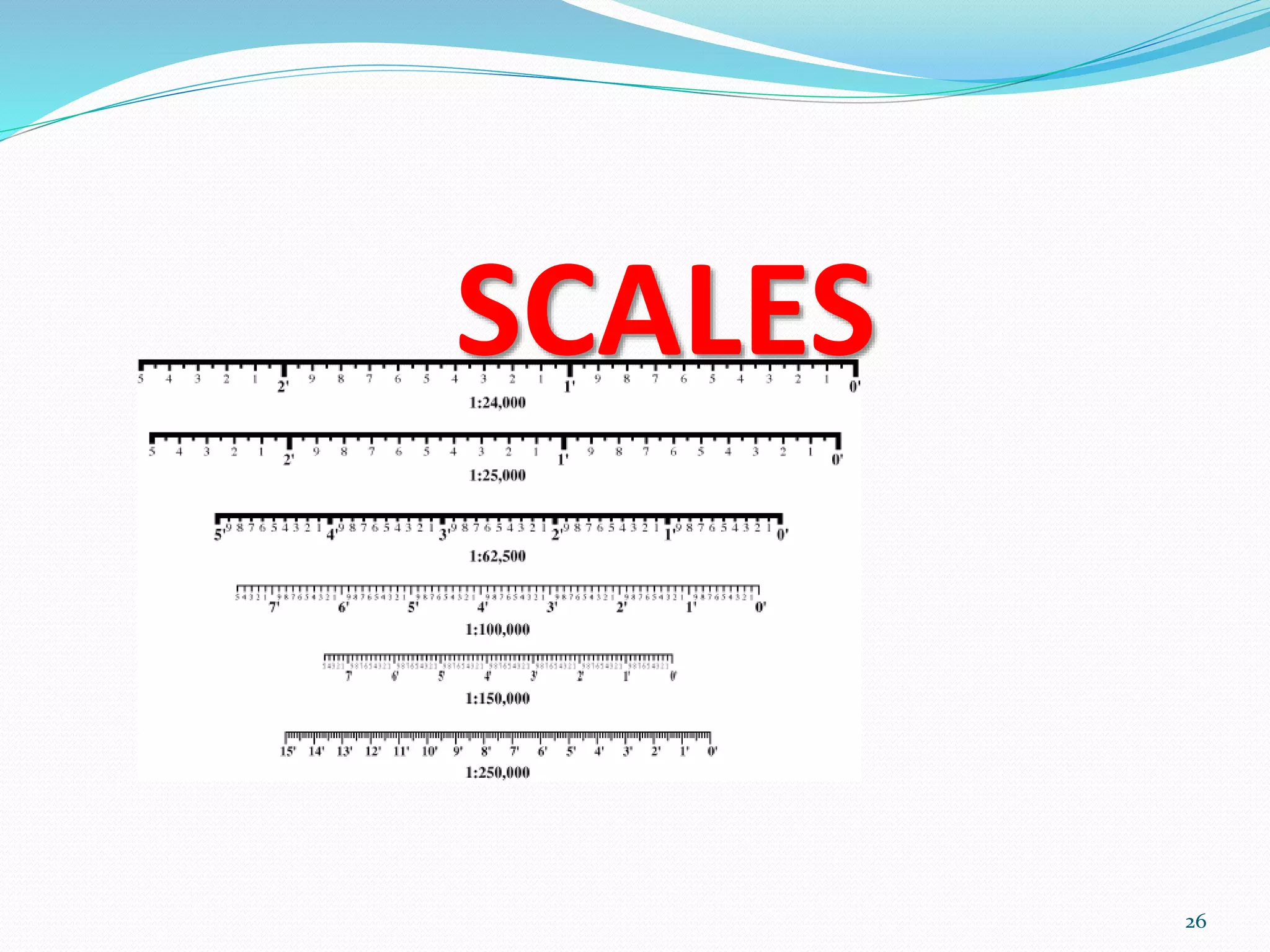
SCALES
Ratio of thelinear dimension of an element of an object as represented in the
original drawing to the real linear dimension of the same element of the
object itself.
• Full Size - A scale with the ratio 1: 1.
• Enlargement Scale - A scale where the ratio is larger than 1 :1. It is said to
be larger as its ratio increases.
• Reduction Scale - A scale where ratio is smaller than 1: 1. It is said to be
smaller as its ratio decreases.
SCALE 1 : 1 for full size
SCALE X : 1 for En-largement scale
SCALE 1 : X for Reduction scales
27
https://in.linkedin.com/in/rishabhnatholia
28.
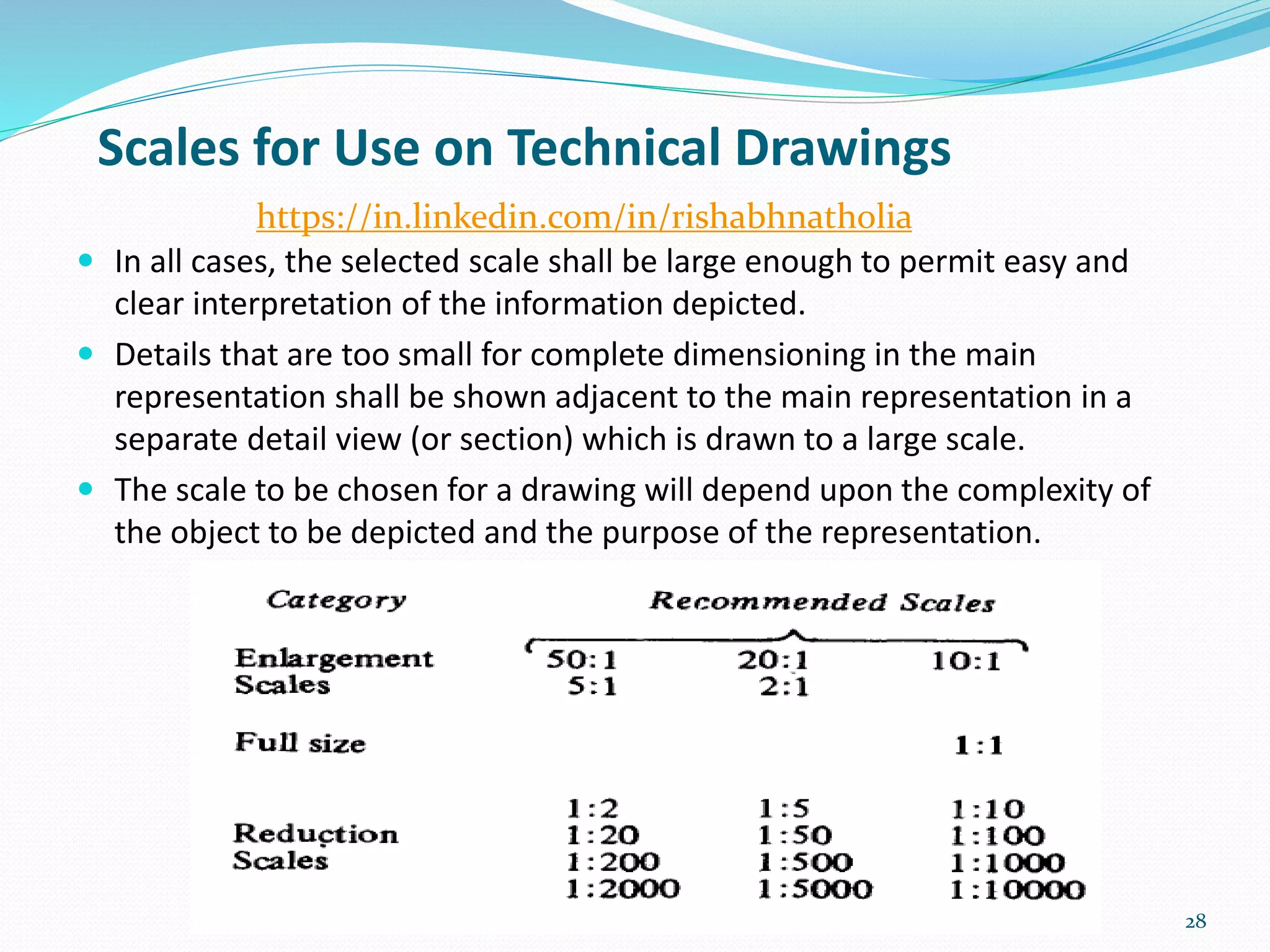
In allcases, the selected scale shall be large enough to permit easy and
clear interpretation of the information depicted.
Details that are too small for complete dimensioning in the main
representation shall be shown adjacent to the main representation in a
separate detail view (or section) which is drawn to a large scale.
The scale to be chosen for a drawing will depend upon the complexity of
the object to be depicted and the purpose of the representation.
28
Scales for Use on Technical Drawings
https://in.linkedin.com/in/rishabhnatholia
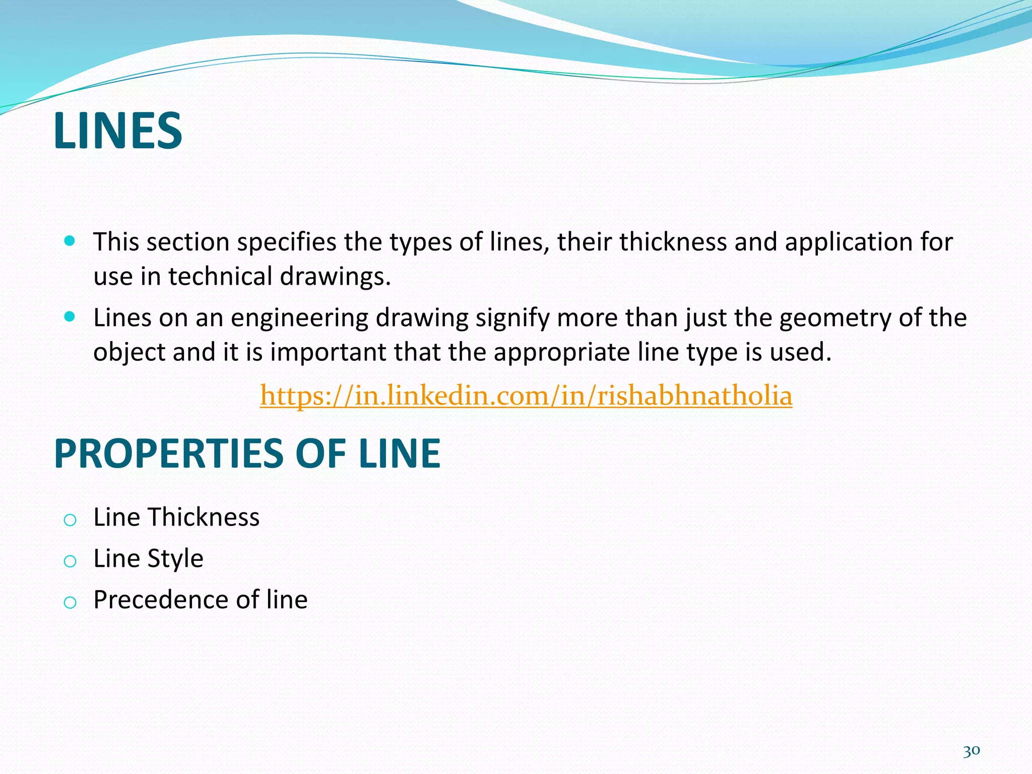
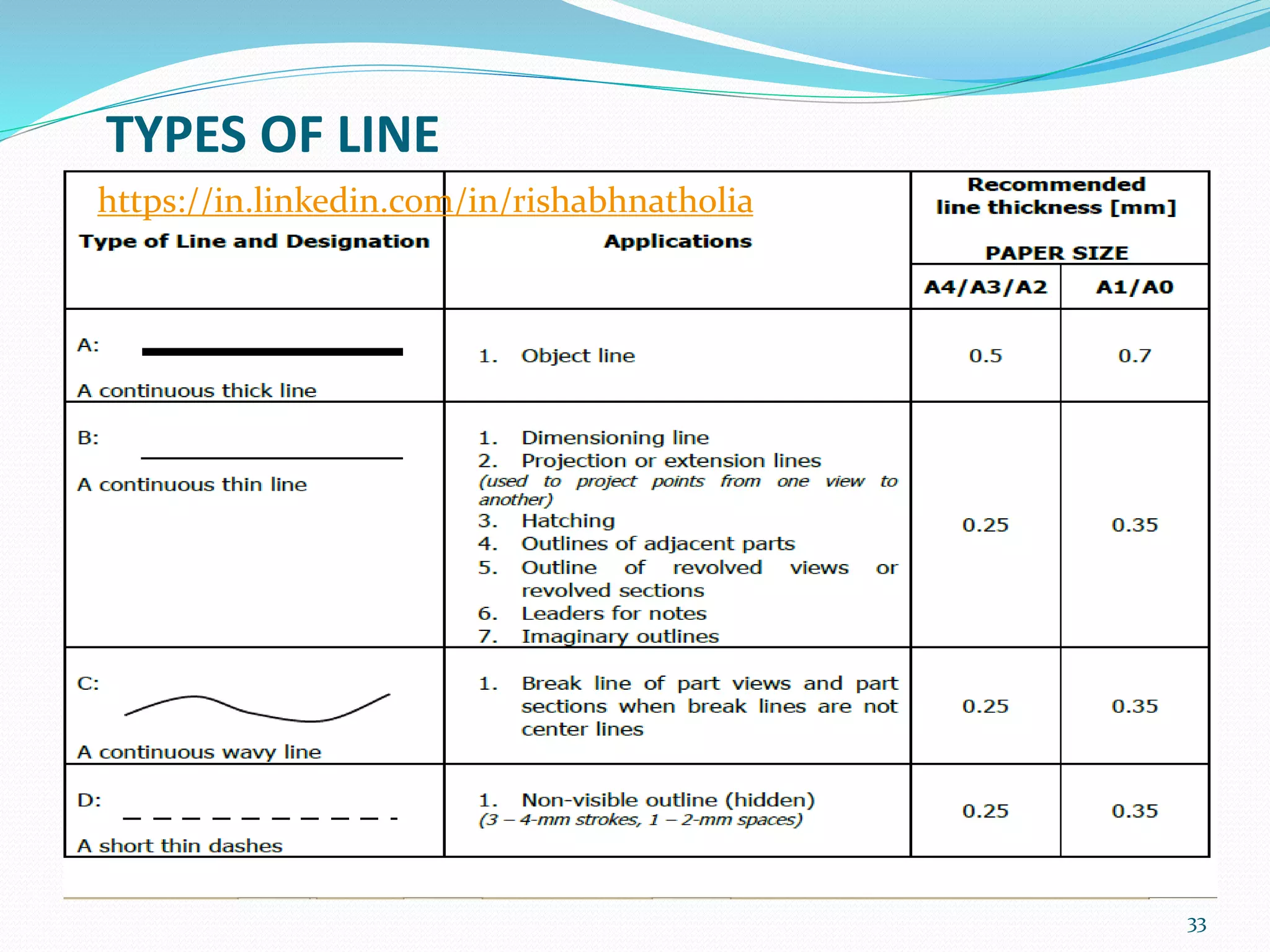
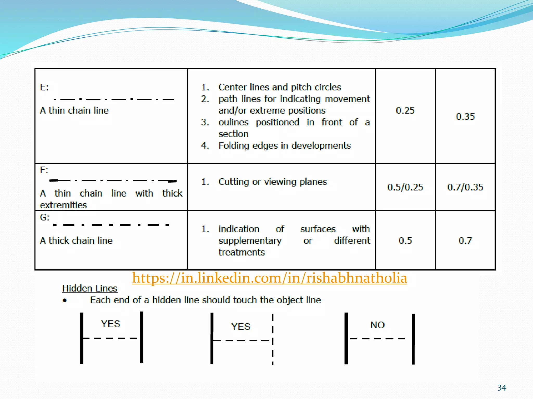
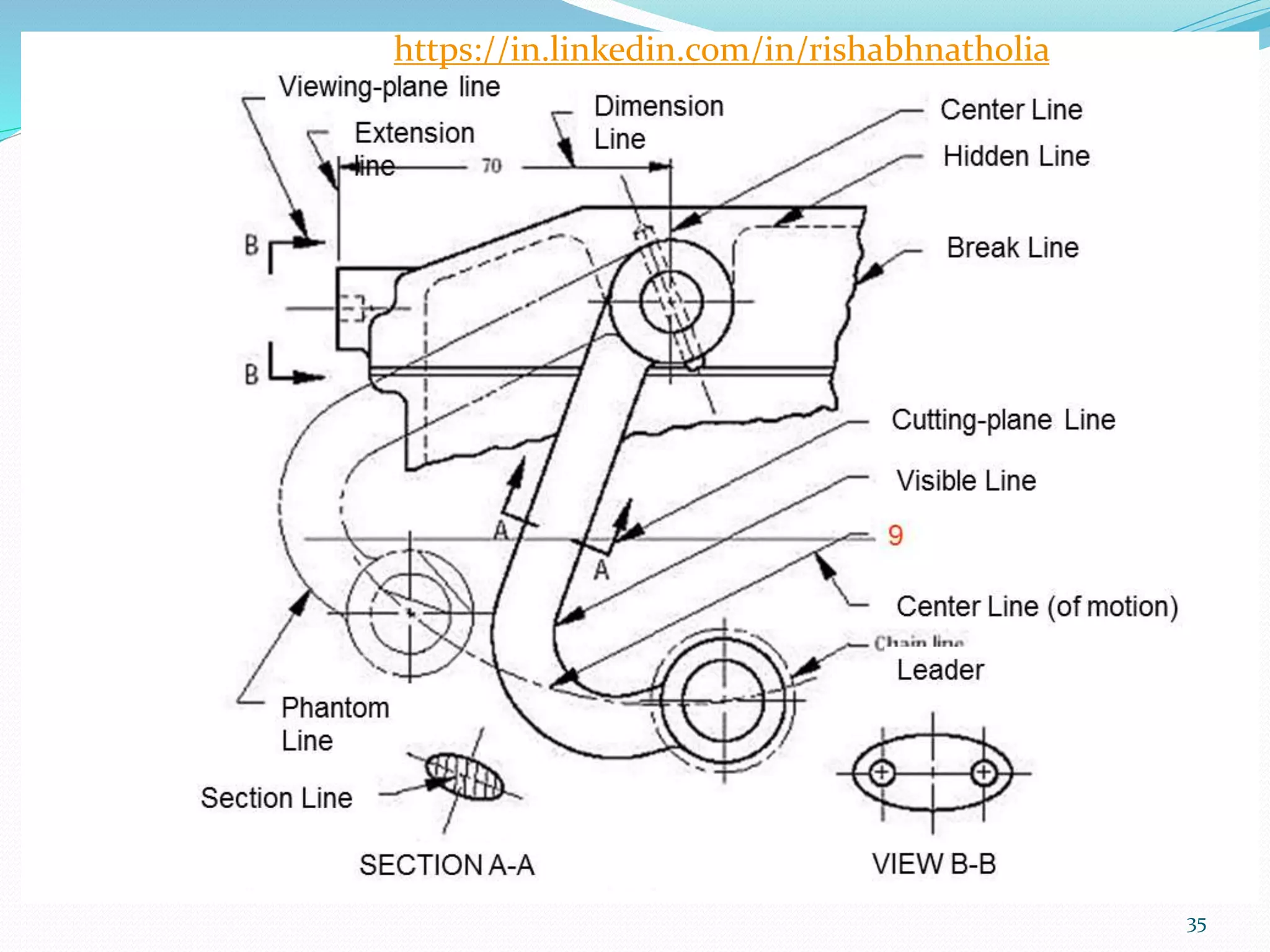
LINES
This sectionspecifies the types of lines, their thickness and application for
use in technical drawings.
Lines on an engineering drawing signify more than just the geometry of the
object and it is important that the appropriate line type is used.
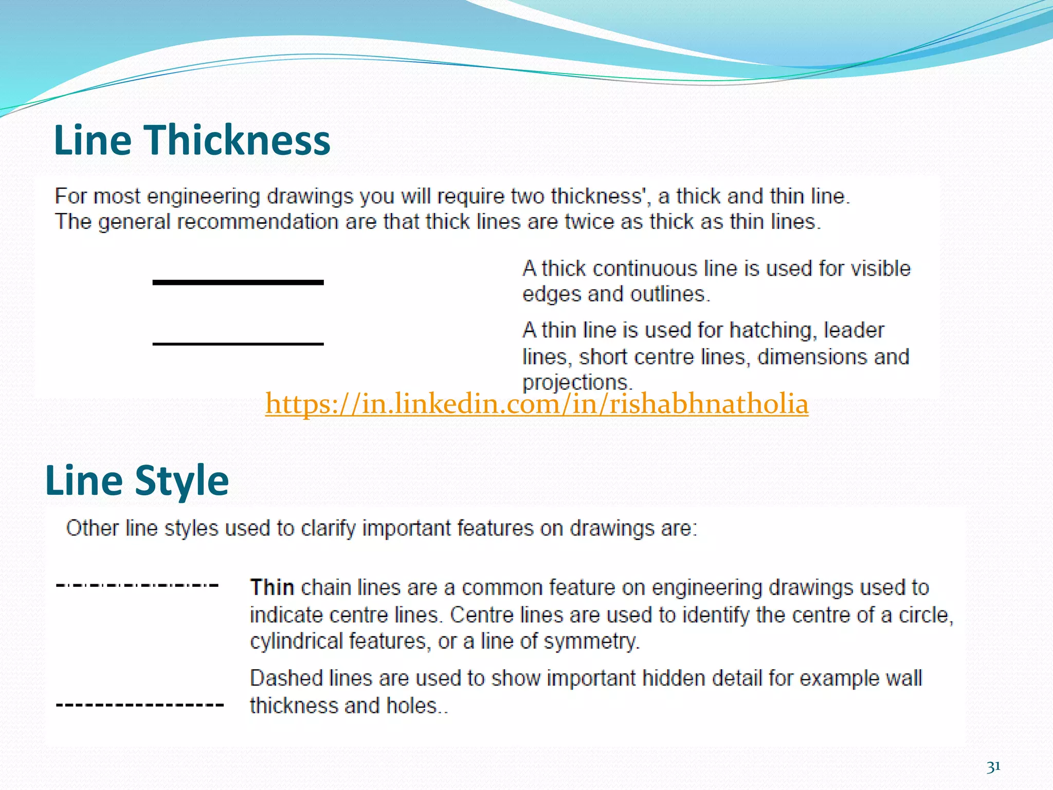
o Line Thickness
o Line Style
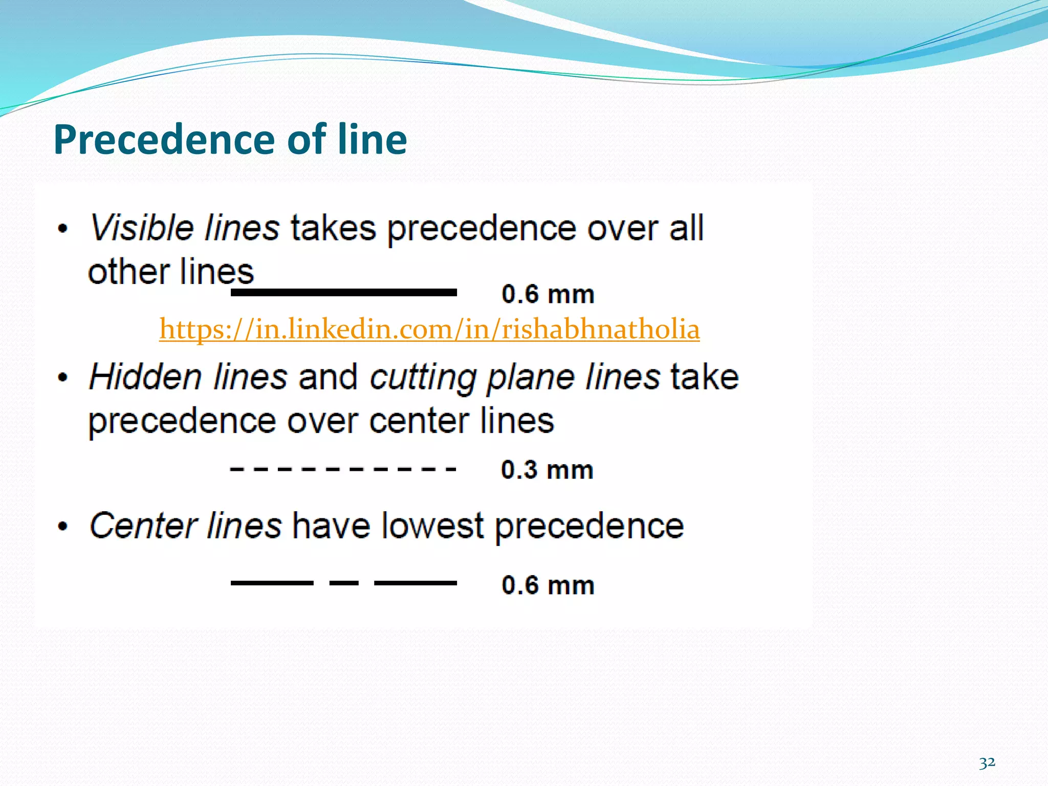
o Precedence of line
30
PROPERTIES OF LINE
https://in.linkedin.com/in/rishabhnatholia
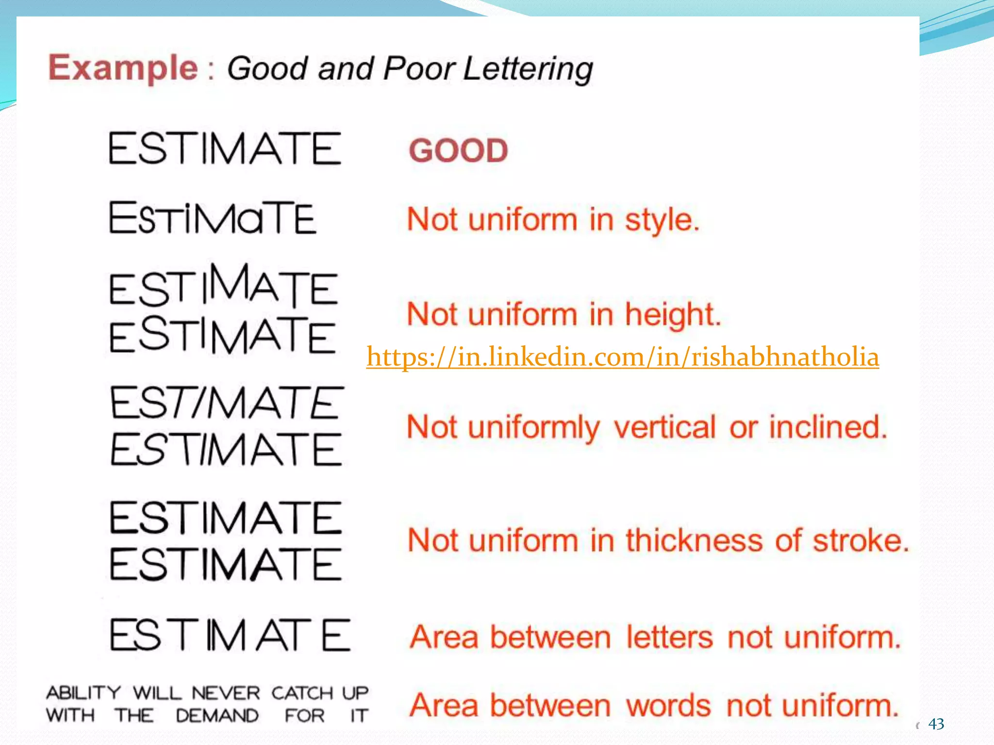
LETTERING
37
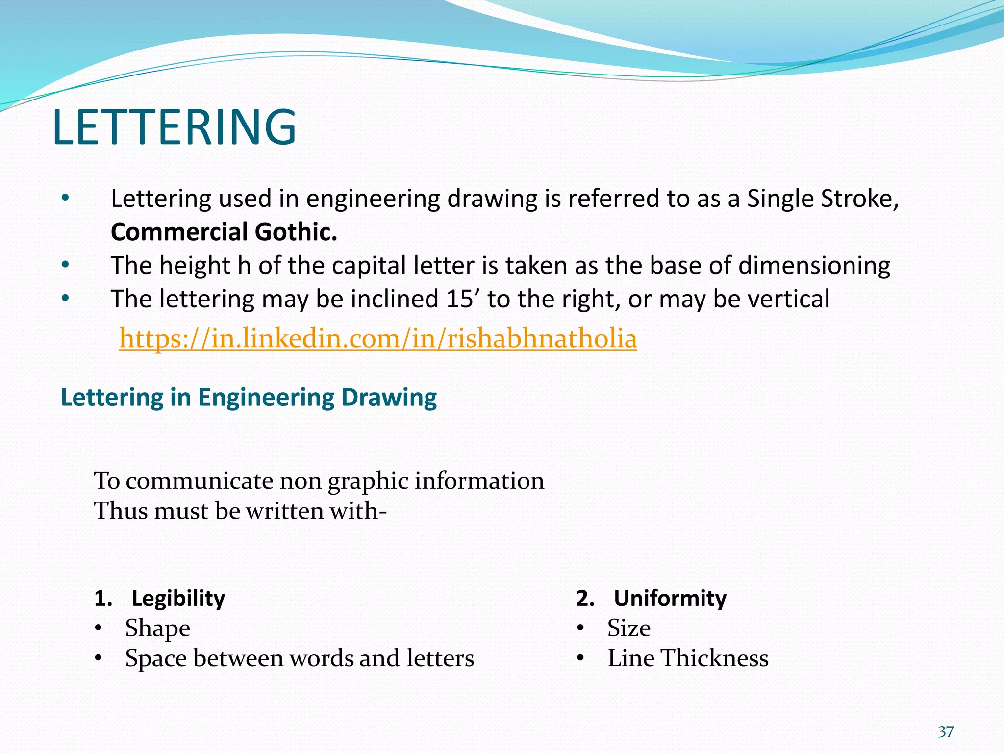
• Lettering usedin engineering drawing is referred to as a Single Stroke,
Commercial Gothic.
• The height h of the capital letter is taken as the base of dimensioning
• The lettering may be inclined 15’ to the right, or may be vertical
Lettering in Engineering Drawing
To communicate non graphic information
Thus must be written with-
1. Legibility
• Shape
• Space between words and letters
2. Uniformity
• Size
• Line Thickness
https://in.linkedin.com/in/rishabhnatholia
42
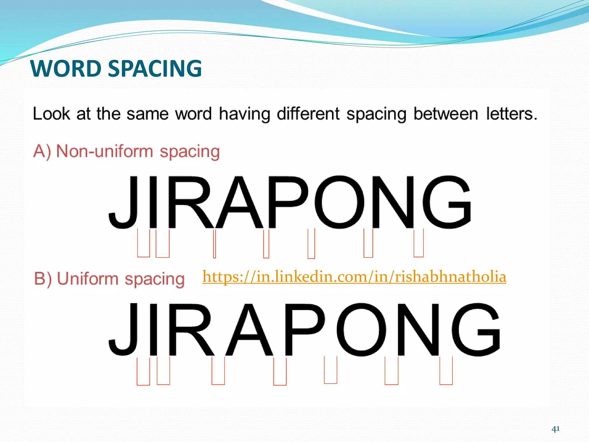
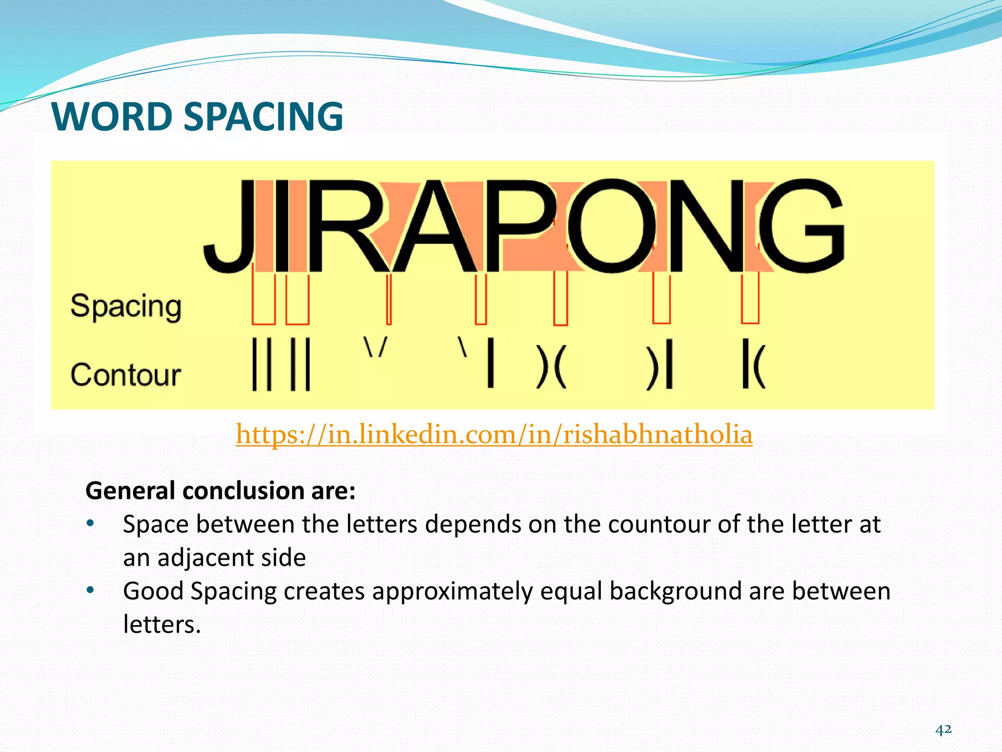
WORD SPACING
General conclusionare:
• Space between the letters depends on the countour of the letter at
an adjacent side
• Good Spacing creates approximately equal background are between
letters.
https://in.linkedin.com/in/rishabhnatholia
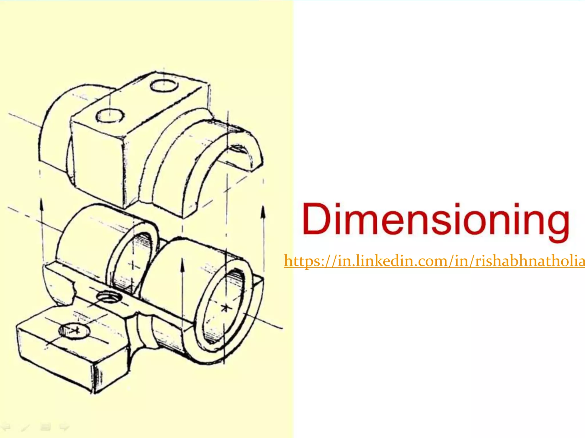
DIMENSIONING
46
Dimension as anumerical value expressed in appropriate units of
measurement and indicated graphically on technical drawings with lines,
symbols and notes.
Units of Measurement: The most commonly used unit for length is the
millimeter. In civil engineering and architectural drawing, inch or foot is often
used as a unit of length. Angles are shown in degrees.
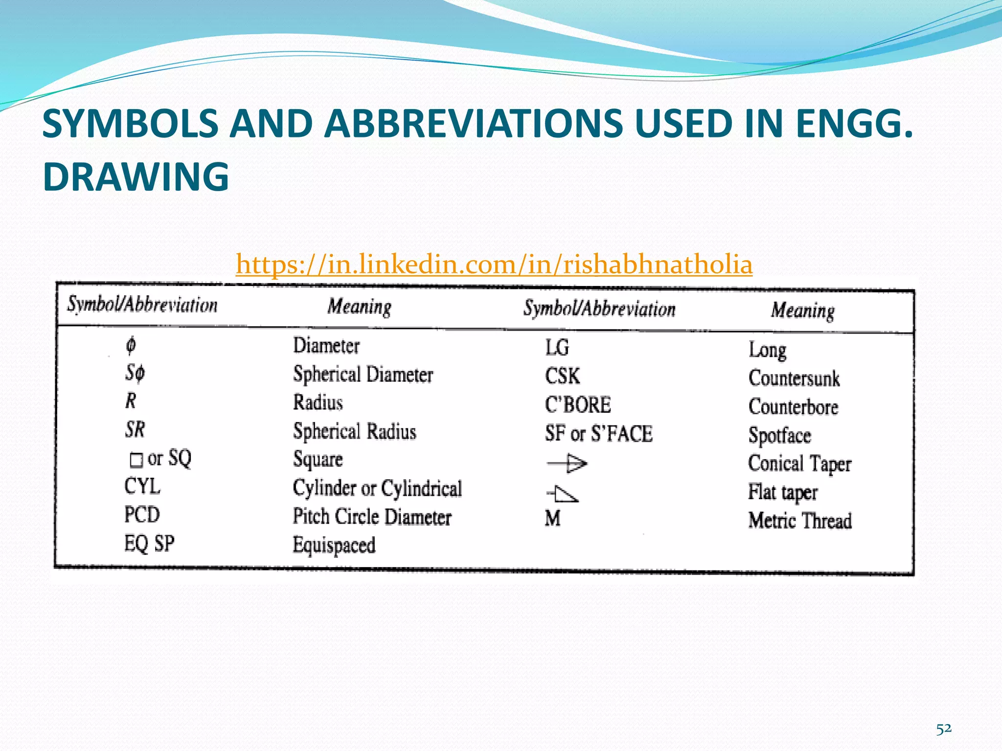
Symbols are incorporated to indicate specific geometry wherever necessary.
Providing information on a drawing about
o Distances (size or functional dimensions)
o Sizes and positions (location or datum dimensions) of holes, grooves and
other features.
o Details relating to manufacture etc.
https://in.linkedin.com/in/rishabhnatholia
47.
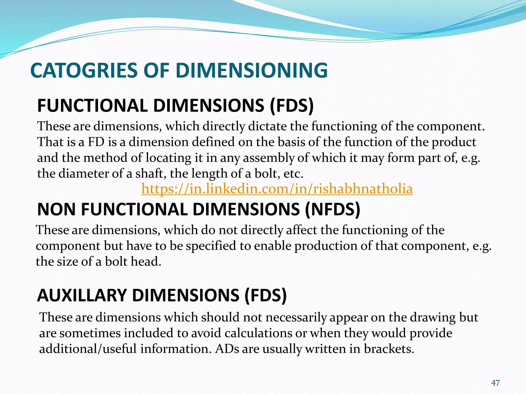
FUNCTIONAL DIMENSIONS (FDS)
Theseare dimensions, which directly dictate the functioning of the component.
That is a FD is a dimension defined on the basis of the function of the product
and the method of locating it in any assembly of which it may form part of, e.g.
the diameter of a shaft, the length of a bolt, etc.
47
NON FUNCTIONAL DIMENSIONS (NFDS)
AUXILLARY DIMENSIONS (FDS)
These are dimensions, which do not directly affect the functioning of the
component but have to be specified to enable production of that component, e.g.
the size of a bolt head.
These are dimensions which should not necessarily appear on the drawing but
are sometimes included to avoid calculations or when they would provide
additional/useful information. ADs are usually written in brackets.
CATOGRIES OF DIMENSIONING
https://in.linkedin.com/in/rishabhnatholia
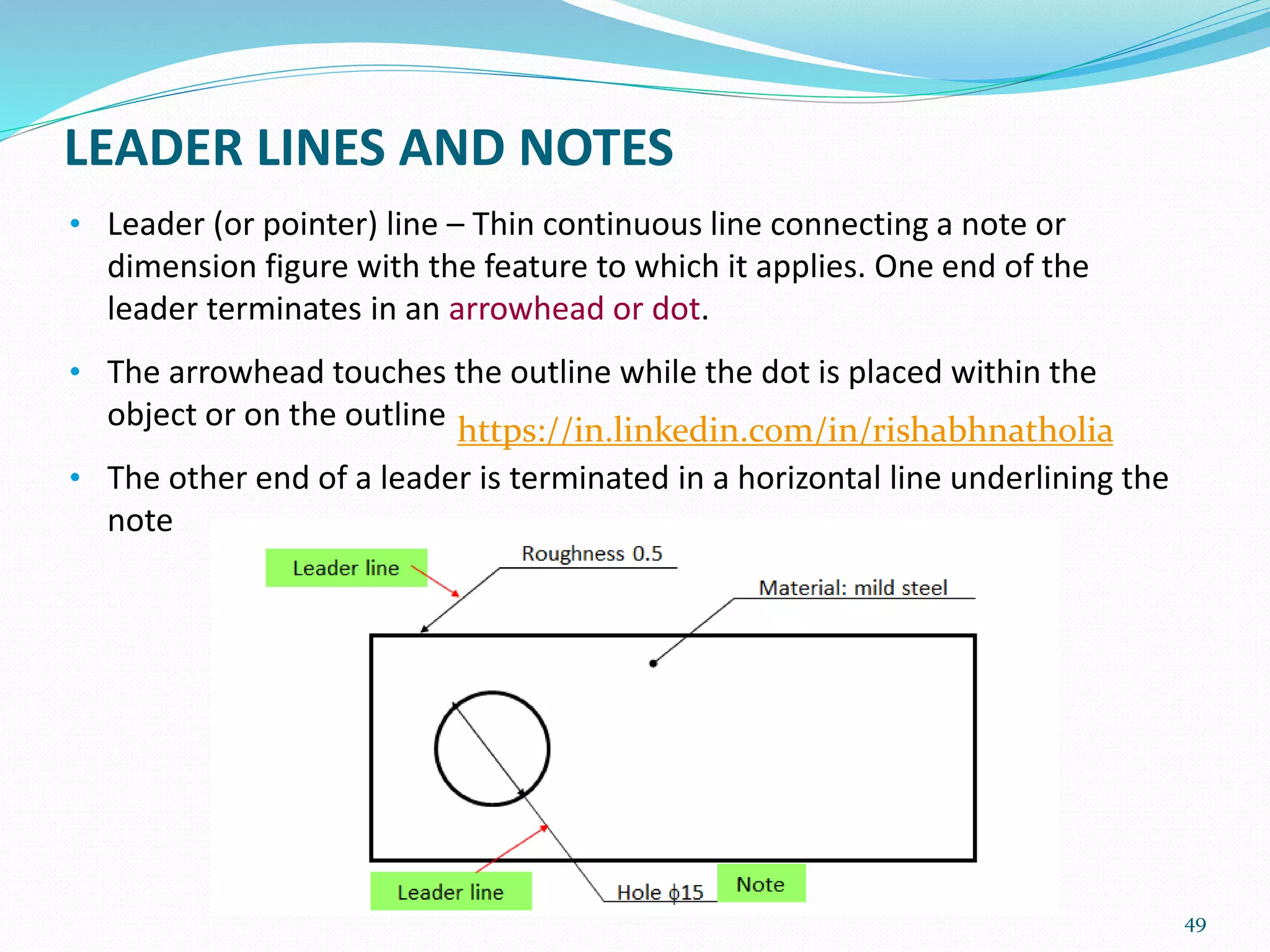
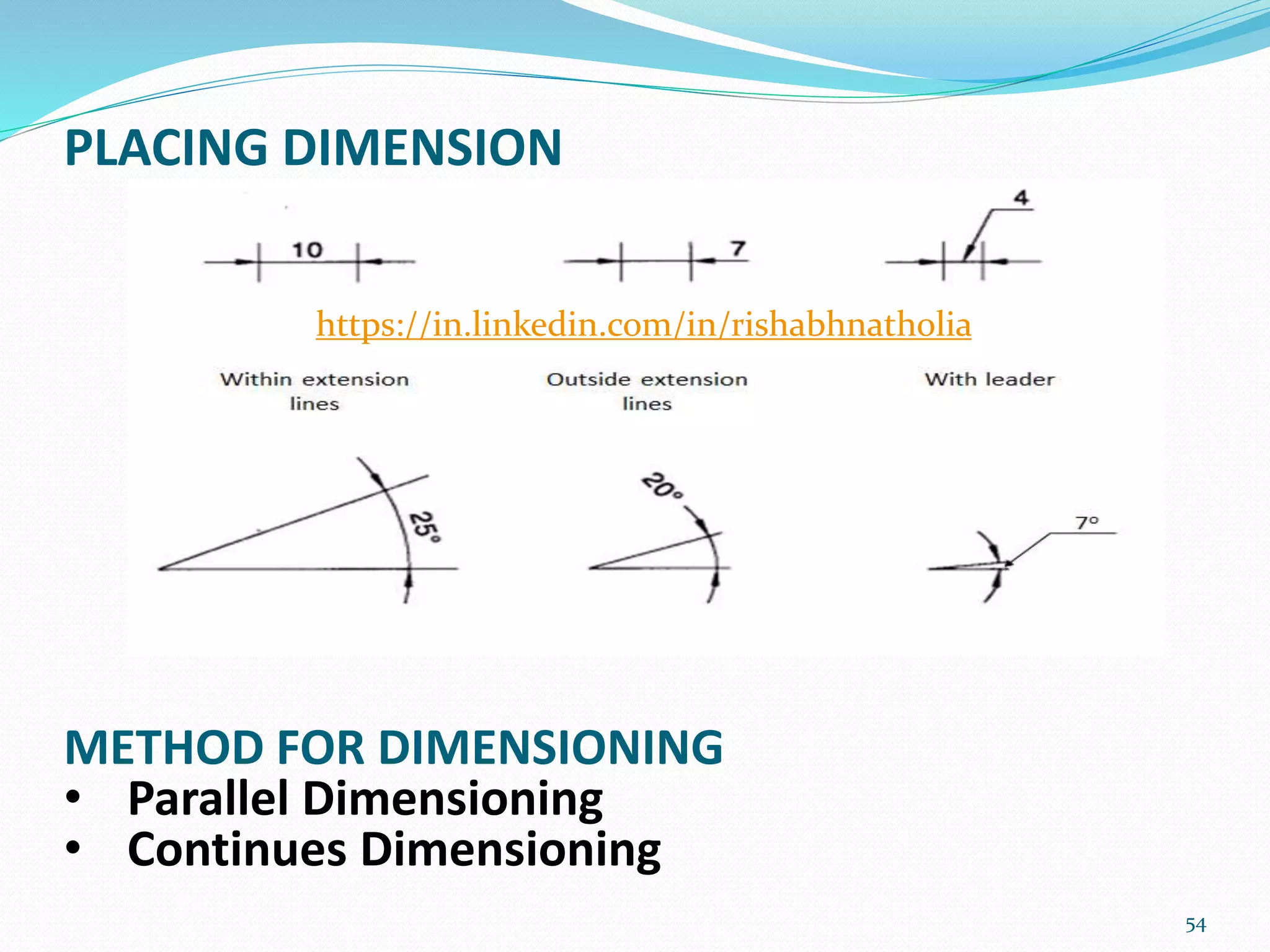
LEADER LINES ANDNOTES
• Leader (or pointer) line – Thin continuous line connecting a note or
dimension figure with the feature to which it applies. One end of the
leader terminates in an arrowhead or dot.
• The arrowhead touches the outline while the dot is placed within the
object or on the outline
• The other end of a leader is terminated in a horizontal line underlining the
note
49
https://in.linkedin.com/in/rishabhnatholia
50.
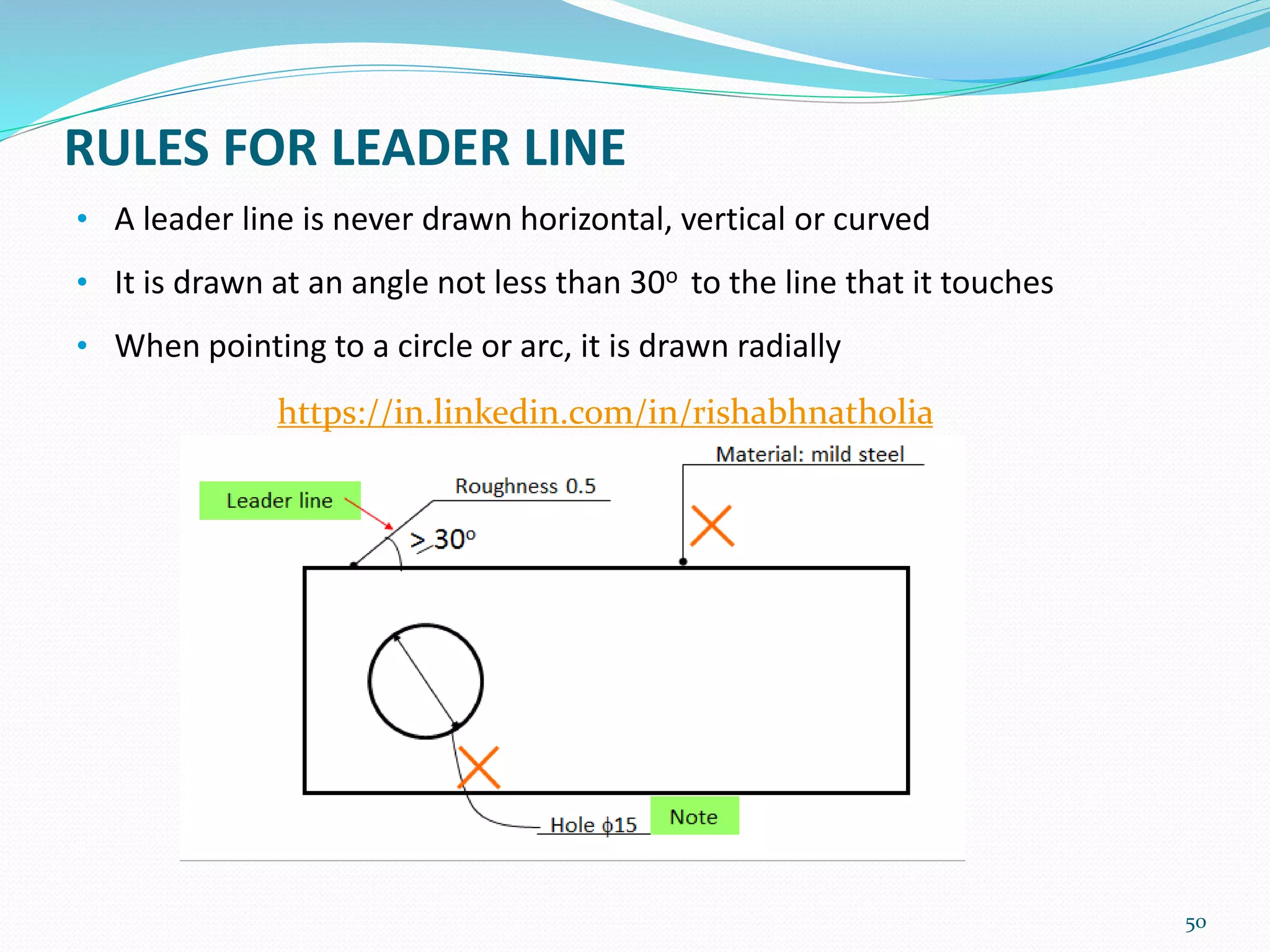
RULES FOR LEADERLINE
• A leader line is never drawn horizontal, vertical or curved
• It is drawn at an angle not less than 30o to the line that it touches
• When pointing to a circle or arc, it is drawn radially
50
https://in.linkedin.com/in/rishabhnatholia
51.
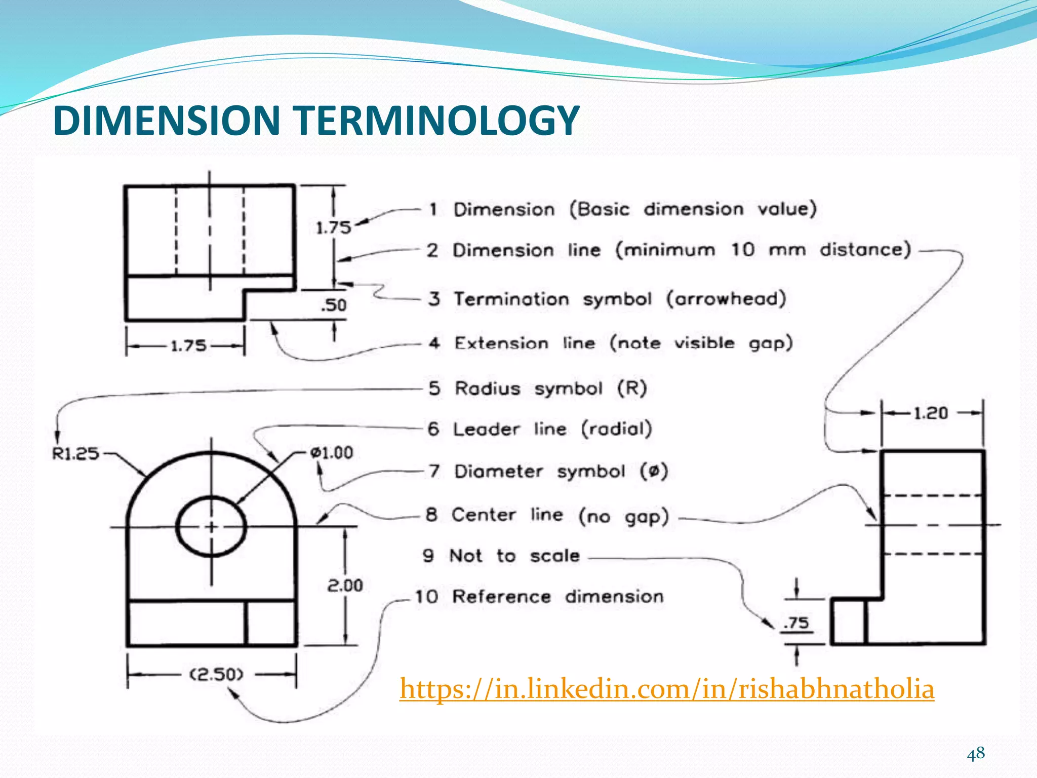
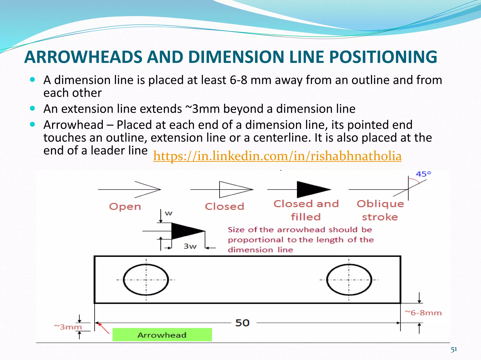
ARROWHEADS AND DIMENSIONLINE POSITIONING
A dimension line is placed at least 6-8 mm away from an outline and from
each other
An extension line extends ~3mm beyond a dimension line
Arrowhead – Placed at each end of a dimension line, its pointed end
touches an outline, extension line or a centerline. It is also placed at the
end of a leader line
51
https://in.linkedin.com/in/rishabhnatholia
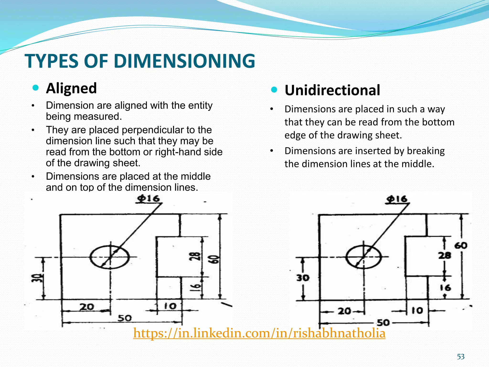
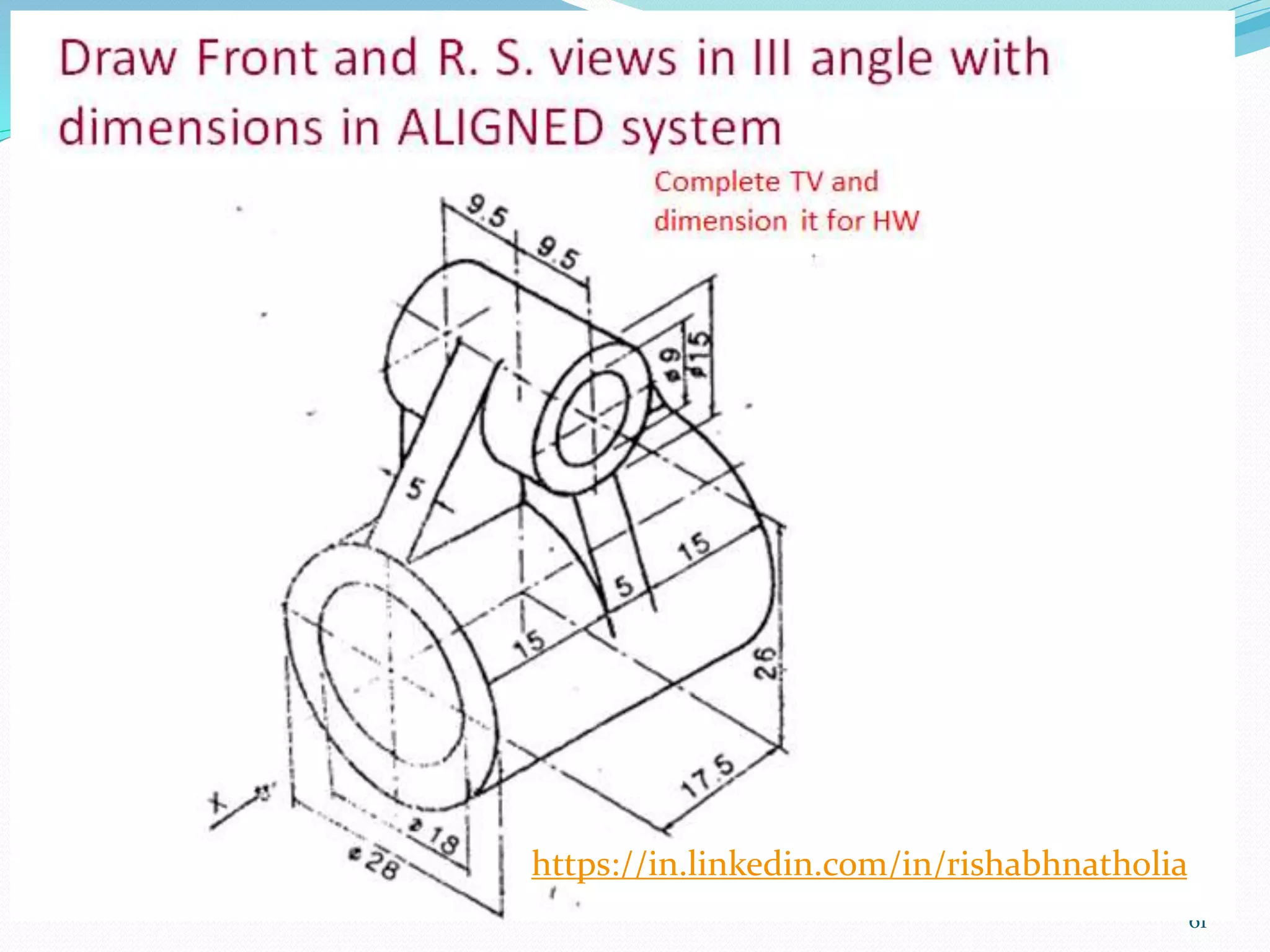
TYPES OF DIMENSIONING
Aligned
• Dimension are aligned with the entity
being measured.
• They are placed perpendicular to the
dimension line such that they may be
read from the bottom or right-hand side
of the drawing sheet.
• Dimensions are placed at the middle
and on top of the dimension lines.
53
Unidirectional
• Dimensions are placed in such a way
that they can be read from the bottom
edge of the drawing sheet.
• Dimensions are inserted by breaking
the dimension lines at the middle.
https://in.linkedin.com/in/rishabhnatholia
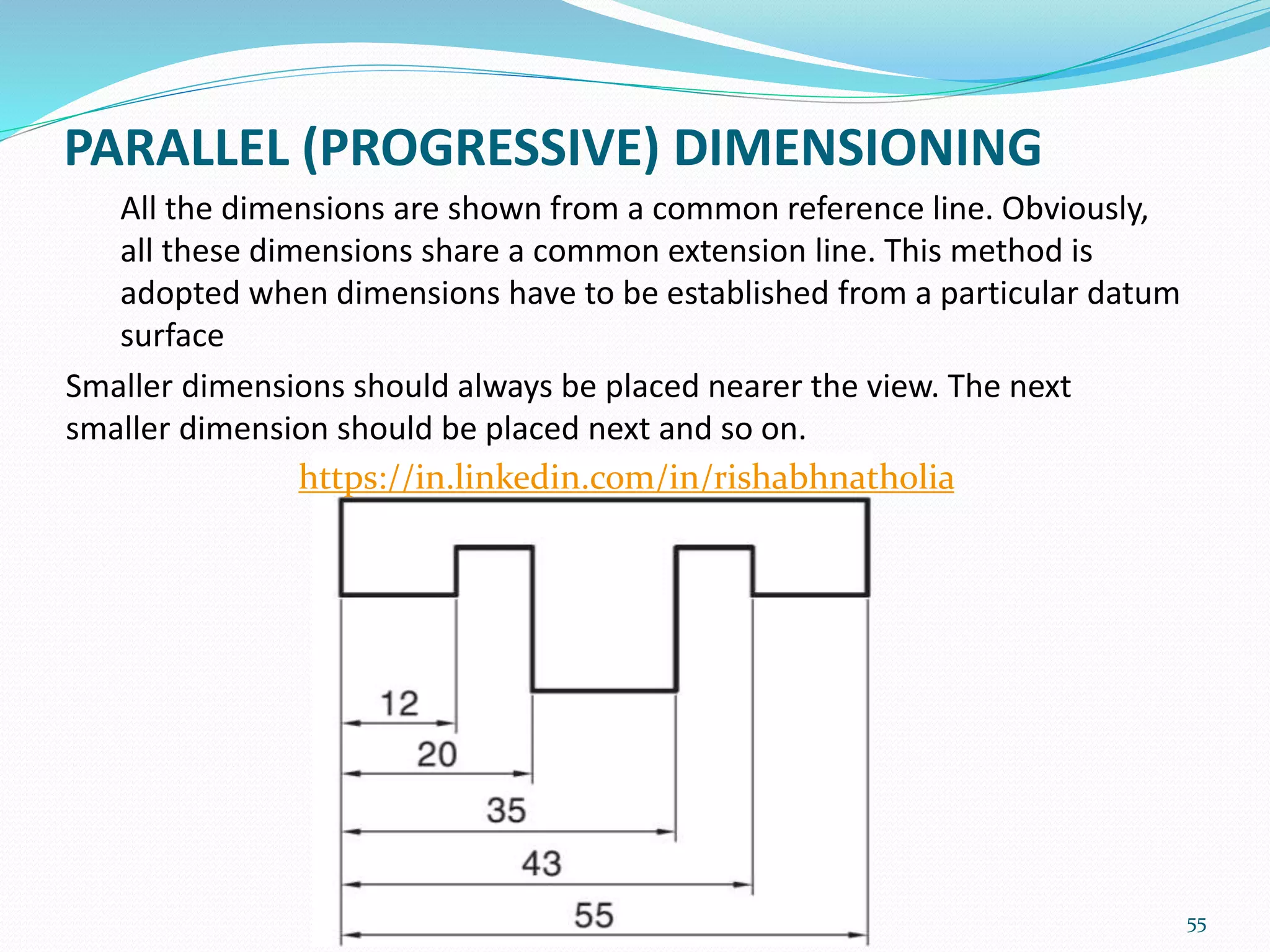
PARALLEL (PROGRESSIVE) DIMENSIONING
Allthe dimensions are shown from a common reference line. Obviously,
all these dimensions share a common extension line. This method is
adopted when dimensions have to be established from a particular datum
surface
Smaller dimensions should always be placed nearer the view. The next
smaller dimension should be placed next and so on.
55
https://in.linkedin.com/in/rishabhnatholia
56.
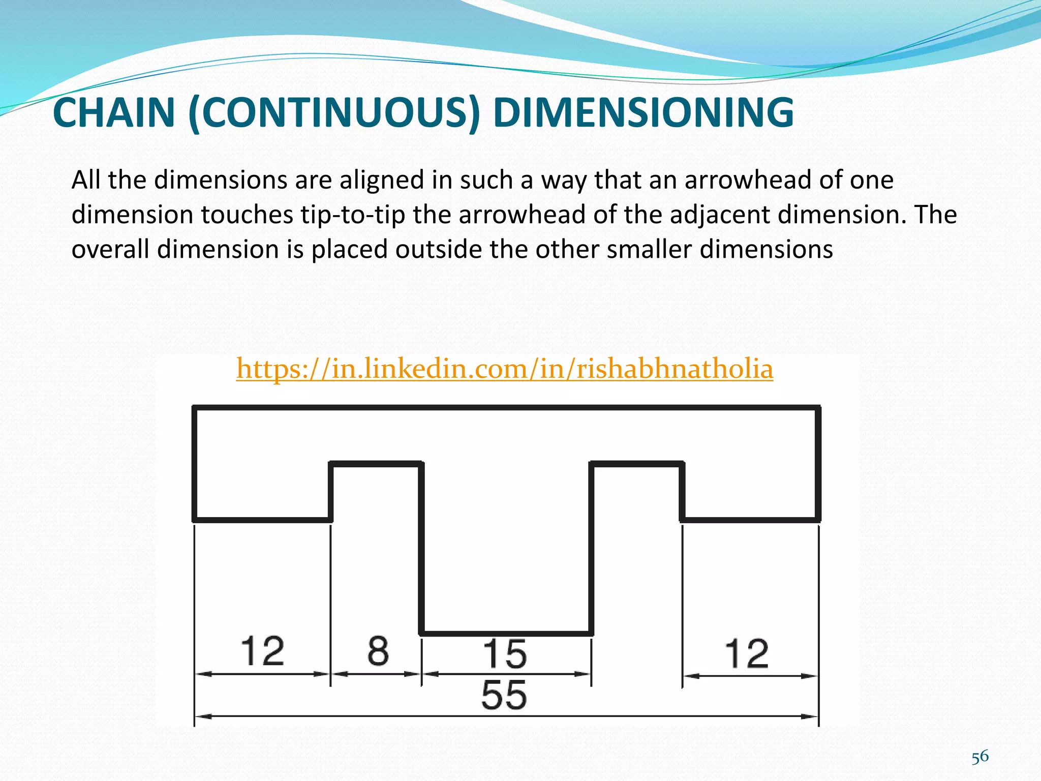
CHAIN (CONTINUOUS) DIMENSIONING
56
Allthe dimensions are aligned in such a way that an arrowhead of one
dimension touches tip-to-tip the arrowhead of the adjacent dimension. The
overall dimension is placed outside the other smaller dimensions
https://in.linkedin.com/in/rishabhnatholia
57.
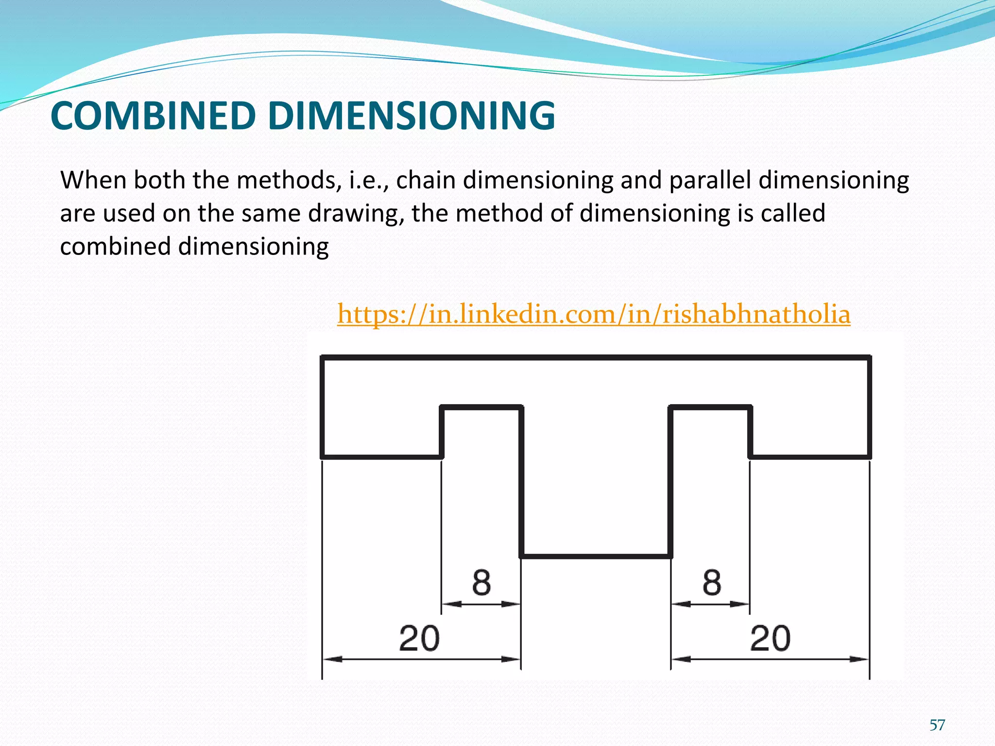
COMBINED DIMENSIONING
When boththe methods, i.e., chain dimensioning and parallel dimensioning
are used on the same drawing, the method of dimensioning is called
combined dimensioning
57
https://in.linkedin.com/in/rishabhnatholia
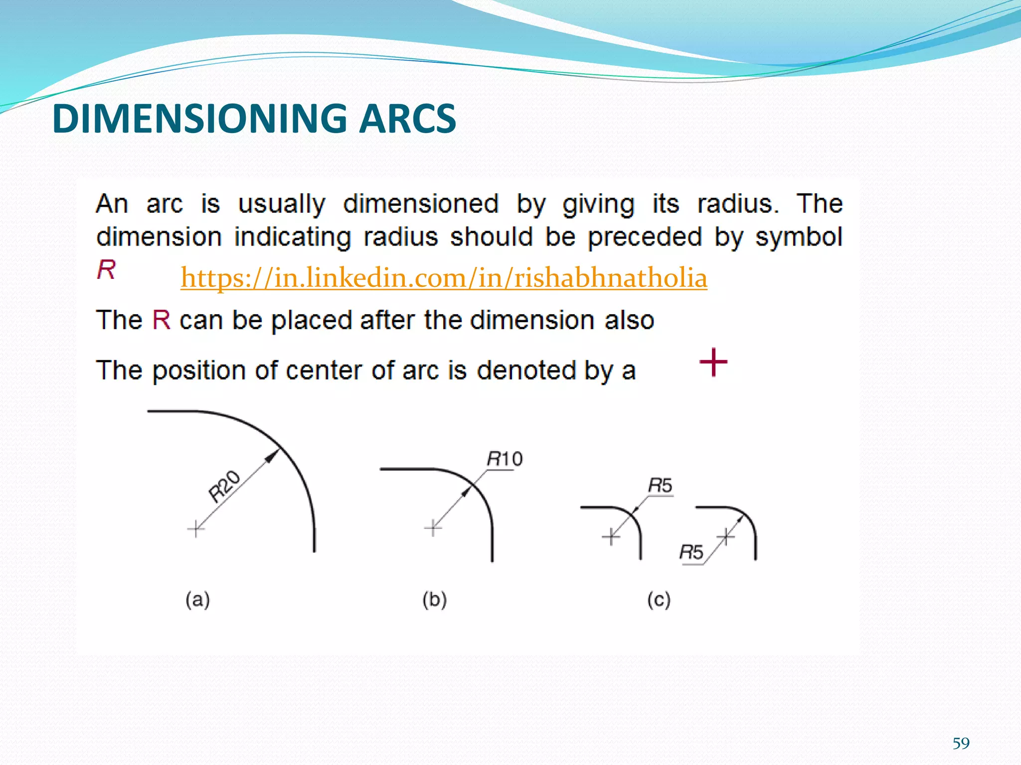
58.
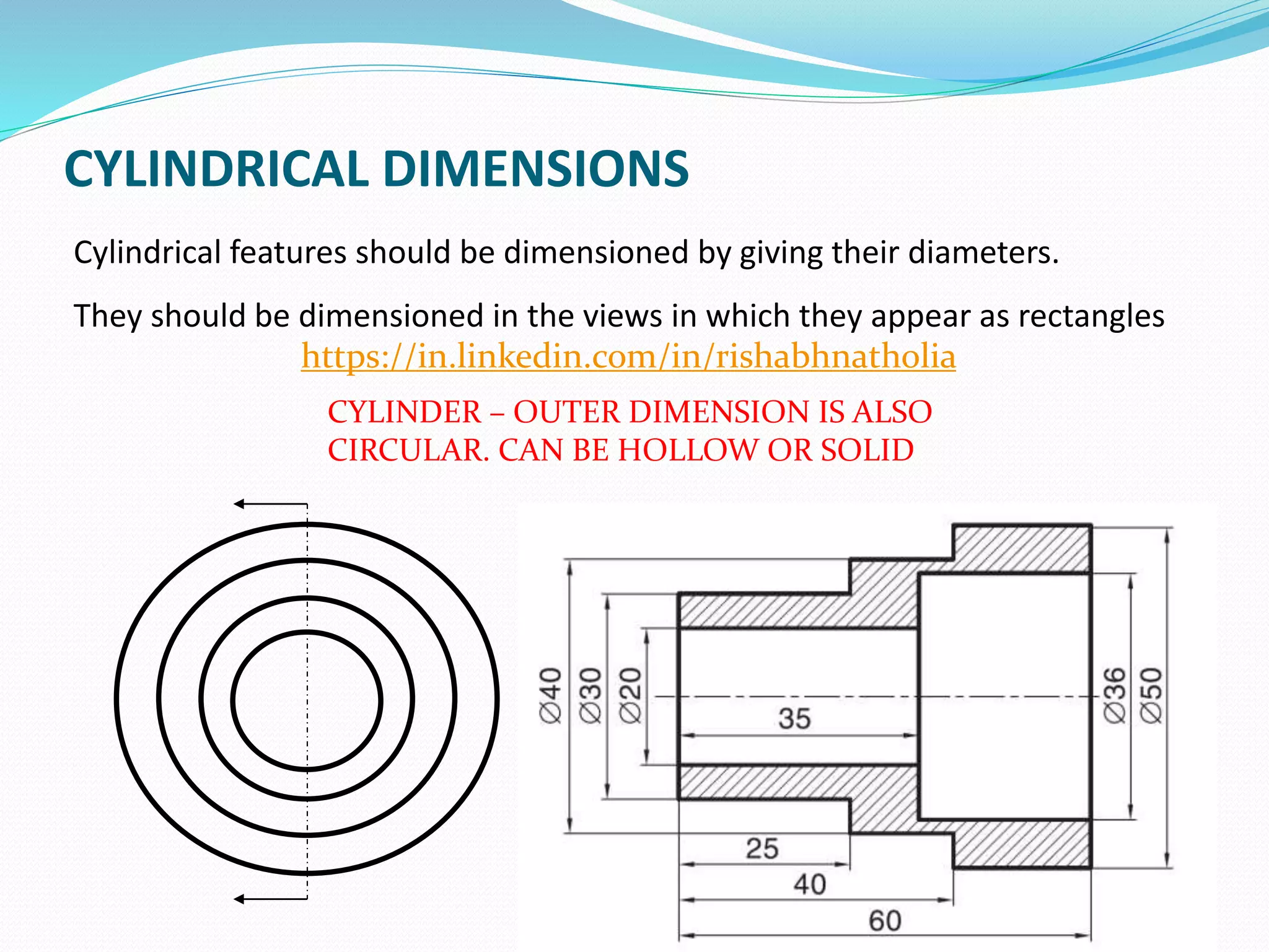
CYLINDRICAL DIMENSIONS
Cylindrical featuresshould be dimensioned by giving their diameters.
They should be dimensioned in the views in which they appear as rectangles
58
CYLINDER – OUTER DIMENSION IS ALSO
CIRCULAR. CAN BE HOLLOW OR SOLID
https://in.linkedin.com/in/rishabhnatholia
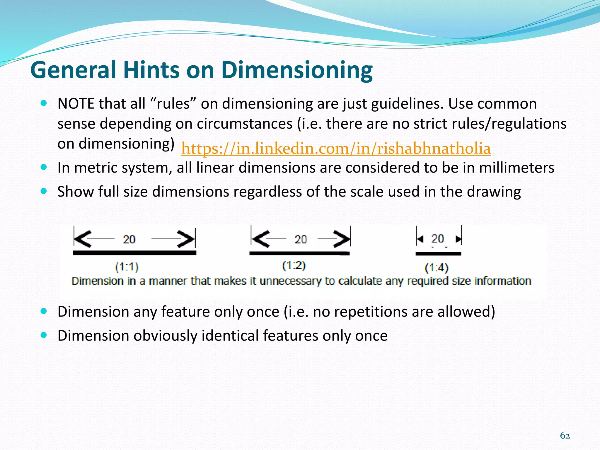
NOTE thatall “rules” on dimensioning are just guidelines. Use common
sense depending on circumstances (i.e. there are no strict rules/regulations
on dimensioning)
In metric system, all linear dimensions are considered to be in millimeters
Show full size dimensions regardless of the scale used in the drawing
Dimension any feature only once (i.e. no repetitions are allowed)
Dimension obviously identical features only once
62
General Hints on Dimensioning
https://in.linkedin.com/in/rishabhnatholia
63.
For any queryor error feel free to mail me :
natholiarishabh@gmail.com
63
https://in.linkedin.com/in/rishabhnatholia


![W1-Introduction to ED [Autosaved].pptx](https://cdn.slidesharecdn.com/ss_thumbnails/w1-introductiontoedautosaved-221025152231-90341e07-thumbnail.jpg?width=640&height=640&fit=bounds)


![PowerISO 9.2 Mac Crack + Serial Key Free Download 2026 [Latest] Software.pptx](https://cdn.slidesharecdn.com/ss_thumbnails/software-251207185653-5d5700e6-thumbnail.jpg?width=640&height=640&fit=bounds)


![AnyTrans for iOS 8.9.14.20251127 With Crack for MacOS [Latest] pptx](https://cdn.slidesharecdn.com/ss_thumbnails/softwareoverview-251207190907-2316965f-thumbnail.jpg?width=640&height=640&fit=bounds)


![Wondershare Filmora 15.0.11 Crack for Mac Key Full Download [Latest] pptx](https://cdn.slidesharecdn.com/ss_thumbnails/software-251207184836-1d16ba16-thumbnail.jpg?width=640&height=640&fit=bounds)
![iStat Menus 7.20 Crack for MacOS 2026 Full Version [Latest] pptx](https://cdn.slidesharecdn.com/ss_thumbnails/softwareoverview-251207191544-22b737dc-thumbnail.jpg?width=640&height=640&fit=bounds)


