SlideShare a Scribd company logo
1 of 16
Download to read offline
Design for Manufacture and Assembly
Datum Systems
235
DATUM SYSTEMS
Design Principles For Locating Components
The movement of any body in space may be resolved into six degrees of freedom
relative to the three co-ordinate axes in figure 1,viz., three of translation in
the directions X, Y and Z and three co-ordination axes OX OY OZ.
Fig.1 Co- ordinate Axes
To fix a body in space relative to any other it is both necessary and sufficient
to introduce 6 constraints. This is the “6 point location principle”.
In figure 2 the block is located precisely in relation to the co-ordinate planes
by 6 hemi-spherical pins, 3 in the base contacting the XOY plane, 2 in the side
contacting the ZOY plane and 1 in the side contacting the ZOY plane.
Fig: 2 “6 point Location Principle” Diagram
Apply these principles in design as far as practicable particularly when precise
location or precise mechanical movements are required.
Note: severe conditions in engineering such as heavy loads, high speeds, etc.,
often necessitate adopting modified principles. An example would be
Design for Manufacture and Assembly
Datum Systems
236
substitution of limited areas of contact for the point contact in figure 2 such as
is often adopted in jig and fixture design. the point contact in figure 2 such as
is often adopted in jig and fixture design.
Fig- 3. Datum Spigot and Recess Assembly
When locating one component relative to any other in an assembly, design so
as to confine the need for positional accuracy to the minimum number of
features, consider datum systems.
Function of Datum Systems
To align certain features on two components in accurate geometric relation
when assembled.
In the flange coupling, figure 3, a spigot B and recess A have been introduced
in the design so as to align the respective shafts on assembly.
To locate mating components accurately to finite assembly facilitates
assembly. In figure 3 the datum spigot and recess also facilitates assembly of
the securing bolts.
To set as a convenient base from which to dimension other features. see
surfaces A and D is figure 4
Design for Manufacture and Assembly
Datum Systems
237
Fig: 4 Datum Based Dimensioning
Common Datum Systems
Group of two or three datum planes
Function
The system using two co-ordinate planes controls the relative movement of two
components in 5 degrees of freedom, while that using three co-ordinate planes
controls them in all 6 degrees of freedom.
Geometric analysis
Geometry involved is flatness and squareness of the planes.
Location accuracy
This is limited by the tolerances for flatness and squareness. The common is
where one plane, usually in largest , is the principal datum, and in others are
referred to this for squareness. see figure 5 where X is the principal datum.
yy
x z
Fig: 5 Locational Accuracy of Principal Datum(X)
Tolerances
Assign flatness tolerances to each principal datum, and squareness tolerances
to the other datums relative to the principal.
X
Z
Design for Manufacture and Assembly
Datum Systems
238
Note: sometimes it may be necessary to assign special requirements to the
flatness tolerance such as “surface must not be convex”, the latter to ensure no
rock when assembled.
Grouped datum plane and spigot assembling
with Grouped datum plane and recess.
Fig: 6 . Positional Datum Groups
Function
This system controls the movement of one component relative to the other in 5
degrees of freedom. The 6th degree not controlled by the system is rotation
about OZ. The two planes control 3 degrees of freedom. Viz., translation in the
Z direction, and rotation about OX and OY; the spigot and recess control 2
degrees of freedom, viz., translation in the X and Y directions. This system is
used as a datum group for position, concentricity or symmetry.
Geometric analysis
The planes are the principal datums with zero position tolerance. The spigot
and recess are the datums with zero position and squareness tolerances all on
MMC, relative to the principal datums. Design the spigot short in length since a
long spigot introduces redundancy by restraining rotational freedom about OX
and OY,which is the function of the planes.
Location accuracy
This is limited only by the fit C between the spigot and recess and the flatness
Design for Manufacture and Assembly
Datum Systems
239
DIA
1
Group
No
.001
DIA
Magnitude
Geometry Tols MMC
No of
Features
1B
(a)
Feature
Letter
POSN
&SQ
Type
Datum
Features
A
Y
-0.304
25.4B
O
A
of the planes. _
Take as criterion C=C±k where C is the mean fit and k is the permissible
variation.
Basic size
Choose this from data sheets as appropriate.
Fit, Design sizes and Tolerances
The fit between spigot and recess should be chosen to suit the location
accuracy required. Confine the choice to the fits given in data sheets.
Do not specify flatness tolerances for the planes unless unusually precise
location is required.
Drawing practice
Show the spigot and plane as one geometric group, and the recess and plane as
another. See figure 7 and use tabular method (a) in general; Method (b) may be
used if there is only one positional groups
Geometric Groups and Tolerances
Design for Manufacture and Assembly
Datum Systems
240
(b)
Fig: 7 (a) Tabular Method (b) sketch for Using one
positional Groups
Example, figure 6
Design requirements
Location accuracy to be for translation 0.0254mm
Basic size for recess and spigot 25.4mm from data sheet
Fit 1.01H8h8 from data sheet giving
Recess: 25.4+0.0305
And spigot: 25.4-0.0305
Location accuracy is 0.0305± 0.0305
This is close enough to the design requirement to be satisfactory.
Grouped Datum Plane , Spigot and Hole
assembling with Grouped Datum Plane,
Recess and Pin. See figure 8.
Function
This system controls the relative movements of two components in all 6 degrees
of freedom, but rotation about OZ less precisely than the others. This system is
used mainly as a datum group for positional features.
Geometric analysis
The planes are principal datums with zero position tolerances. The spigot and
recess are datums with zero position and squareness
tolerances on MMC relative to the principal datums.
Design for Manufacture and Assembly
Datum Systems
241
Fig:8 Spigot & Hole with Recess & Pin Assembly (Grouped
The hole and pin are datums having position and squareness tolerances MMC
relative to the datum spigot and plane and the datum spigot and plane and the
datum recess and plane
Design spigot short in length for the same reason as in 3.22 above.
Location accuracy
Translational movement in the X, Y and Z directions is limited by the fit C
between the spigot and recess and by the flatness of the planes. Take as
before the criterion.
_
C=C±k
Rotation about OX and OY is limited by the flatness of the planes, about OZ by
the fit between the spigot and recess and the hole and pin. The clearance
between the latter including provision for the position tolerances for the
position tolerances for the hole and pin. Take as criterion the mean angular
play.ie, at minimum material conditions with no positional errors present.
Design for Manufacture and Assembly
Datum Systems
242
Geometric Groups and Tolerances.
1
Group
No
0.1 dia
O dia
Magnitude
Geometry Tols MMC
No of
Features
1B
C 1
Feature
Letter
POSN
&SQ
POSN
&SQ
Type
Datum
Feature
A
Fig: 9 (a)
9(b) Examples.-Grouped Datum Planes with spigot
and Hole Assembly
Basic Sizes
Choose from data sheets as appropriate.
Fits, design Sizes and Tolerances
The fit between the spigot and recess should be chosen to suit the location
accuracy required. Confine your choice to the fits shown in data sheets 4,5 and
6 for Hole basis; Hole Basis is preferred.
Do not specify flatness tolerances for the planes unless unusually location is
X
Y22.0T.P
A
25.000
5.000 DIA C
+.075
Datum Face A
POSN & SQ TOL O dia MMCdia B
+0.003
POSN & SQ TOL
0.1 dia MMC
Datums Spigot B MMC
& Face A.
5.000 DIA
+.075
22.0T. Y
C
X
+0.003
25.000 dia B
A
Design for Manufacture and Assembly
Datum Systems
243
required.
The fit between the hole and pin must satisfy the location accuracy required
and also provide sufficient C min to allow for position tolerances. Confine your
choice of fit to those given for positional fits in data sheets; the shaft basis will
be applicable here.
Drawing practice
Show the plane, spigot and hole as one geometric group, with the plane as
principal datum for the group. See figure 9(a). Similarly the plane would be
shown as principal datum for the recess and the pin in the other component.
The tabular method (a) in figure 9 is preferred in general; method (b) may be
used if there is only one positional group other than the datum group.
Example.
Fig:10.Spigot & Hole with Recess & Pin Assembly
(Grouped Datum Planes)
Design requirements:
Location accuracy to be
For translation 0.03 0.03mm
For rotational 40 minutes of arc
Basic size,
For recess and spigot 25.0mm
For pin and hole 5.0mm
Design for Manufacture and Assembly
Datum Systems
244
Both from data sheet
Choose hole basis for both fits.
Assign position tolerances as follows:
For spigot 0 dia MMC
For hole 0.15 dia MMC
For recess 0 dia MMC
For hole for pin 0.15 dia MMC
For concentricity
Of two dies of pins 0.04dia MMC
Cmin for spigot and recess
=0+0.10
=0
For hole and pin = 0.15+0.15+0.04+0.04
= 0.38
Provisional design sizes are as follows:
Recess=25.0: spigot=25.0
Pin = 5.0-0.38: hole = 5.0
=4.62
Choose fits from data sheet as follows:
Spigot and recess = 25.0 H8h9
Giving recess 25.000+0.033
And spigot 25.000-0.033
And hole and pin 5.0 H7h9
Giving hole 5.000+0.075
And pin 4.73-0.03
The location accuracy for translation
=0.033+/-0.033
This is regarded as satisfactory.
The maximum angular play
=(5.075-4.700)+(25.033-24.963)*10800/n
=69 minutes of arc.
Criterion for location accuracy is therefore 35 minutes of arc approximately
and hence is satisfactory.
The position tolerances for the pin and the corresponding hole would be
modified to suit the new Cmin 0.21let position tolerance
For hole =0.1 dia MMC
For pin =0.1 dia MMC
For concentricity of
two diameters of pin= 0.01dia MMC
And let C=0.03
See figure 9
Grouped Datum Plane, Spigot and Tongue,
Design for Manufacture and Assembly
Datum Systems
245
Assembling with Grouped Datum Plane,
Recess and Gap. (Fig 11)
Fig: 11. Spigot & Tongue Assembling with Recess
and gap (Grouped Datum Planes)
Function
This system performs a similar function to 3.3 above, except that rotation
about OZ can be more precisely controlled.
Geometric Analysis
For the planes, spigot and recess same remarks apply as in 3.32. The tongue
and gap are also datum related to the other datums, but tolerances are
assigned for symmetrically and squareness instead of for position and
squareness.
Location Accuracy
In principle the same remarks apply as in 3.3.
Basic sizes
Choose from data sheets as appropriate
Fits, Design sizes and Tolerances
In principle the same remarks apply as in 3.3 above, except that the symmetry
tolerance for the tongue relative to the spigot or for the gap relative to the
Design for Manufacture and Assembly
Datum Systems
246
recess can be small, even zero on MMC.This requirement is much easier to
attain with this design than with the corresponding position tolerances in
section 3.3. Confine your choice of fit to those given in data sheets for hole
basis; another data sheet for shaft basis; hole basis is preferred
Drawing practice
Show the plane, spigot and tongue as one geometric group with the plane as
principal datum for the group see figure 9(a). Similarly the plane would be
shown as the principal datum for the recess and pin other geometric group.
The tabular method (a) in figure 9 is preferred in general; Method (b) may be
used if there is only one positional group other than the datum group.
.
Fig 12(a)
Fig 12 (b)
Design for Manufacture and Assembly
Datum Systems
247
Grouped Datum Plane and Pins assembling
with Grouped Datum Plane and Holes. See
Figure 13
Fig 13 Grouped Datum Plane and Pins assembling with Grouped Datum
Plane and Holes
Function
This system controls the relative movements of the two components in all 6
degrees of freedom and in principle relation as precise as translation. The two
planes control 3 degrees of freedom viz. Translation in X and Y directions and
rotation about OZ.
Datum planes
Datum pins
O
Datum plane
X Y
O
Datum holes
1.2 TP
Y
Z
2 Holes
0.21500±0.0009 dia
X
Z
Design for Manufacture and Assembly
Datum Systems
248
Fig :14 Tabular method. Plane as datum for pins
Geometric Analysis
The planes are principal datums with zero position tolerances. The pins and
holes are datums with position and squareness tolerances
on MMC related to their respective principal datums.
Location Accuracy
Translation in the Z direction and rotation about OX and OY is limited by the
flatness of the datum planes. Translation in the X and Y directions and
rotation about OZ is limited by the fit between the holes and pins the
clearance between the later including provision for the position tolerances for
the holes and pins. Take as criterion the mean angular play calculated as half
the maximum angular play ie at minimum material conditions with no
positional errors present.
Magnitude
2 Holes
0.21500±0.0009 dia
1.2 TP
No of
Features
Letter
Group
No
B
1 2
POSN
&SQ
.001
DIA
Geometric Groups & Tolerances
Feature Geometry Tols MMC
Type
2.9 TP
A
1.2 TP
2 Holes
0.21500±0.0009 dia
A
Datum
Feature
2.9 TP
A
Design for Manufacture and Assembly
Datum Systems
249
Basic Sizes
Choose from data sheets 2 or 3 as appropriate.
Fits, Design Sizes and Tolerances
Do not specify flatness tolerances for the planes unless unusually precise
location is required.
The fits between the holes and pins must satisfy the location accuracy
required and also provide sufficient Cmin to allow for position tolerances .
Assign the same position tolerances to each pin and to each hole. Confine your
choice to the positional fits in data sheets 4 and the shaft basis may well be
applicable here see data sheet 7.
Drawing practice
Show the plane and the two holes as one geometric group with the plane as
datum for the group. see figure 14similarly the plane would be shown as
datum for the pins in the other geometric group. The tabular method (a)in
Figure 1.14is preferred in general method (b) may be used if there is only one
positional group other than the datum group.
Example, Figure 14
Design Requirement
Location accuracy to be for rotation of 3 minutes of arc
Basic size for pins and holes 6.35mm from data sheet2
Fit (on shaft basis)6.35 h8c9 from data sheet 7
giving pin 6.35 -- .0009
and hole 6.4262 + .0014
Cmin =.003 permitting .0015 dia MMC position tolerances for the pins and
the holes.
The maximum angular play
=(.00531.5) x(10.800/Ď€)
=12 minutes of are approx.
Criterion for location accuracy is 6 minutes of arc and this is too great in
relation to the design requirement.
Choose fit (on shaft basis) as 6.35 h8E8 from data sheet 7
giving pin 6.35 -- .0009
And hole 6.4262 + .0009
The maximum angular play
=(.00281.5) x (10.800/Ď€)
=6.5 minutes of are approx.
Criterion for location accuracy is thus 3.25 minutes of arc and in this case is
regarded as satisfactory.
Cmax = -.001
Position tolerances for strict interchangeability would be .005 dia but are
considered to be too small.
If we choose .001 dia MMC position tolerances for both the pins and the holes
the virtual sizes of pin and hole become secured and then drilled and reamed
for the insertion of dowels, which are normally a press fit.
Design for Manufacture and Assembly
Datum Systems
250
If the cover Figure 1.13 were dealt within this way a suitable note would be
inserted on the management drawing such as in figure 1.14. The t chosen here
is 6.35h8s7. The holes B would then not ensure strict interchangeability
between components but is an economical solution for small to medium Pin
.251and Hole .250
Thus theoretically giving interference. However the metal interference will be
only on one side of each pin and hole and will not be greater then .0005 Hence
the fits and tolerances chosen are regarded as satisfactory.
Use of Dowels
This system is similar in design to the datum system of section 3.5 However
the dowels generally play no part in the control during production. Usually the
components are assembled together adjusted quantity production.
Fig 15: Tabular method. Plane as datum for pins
In the datum systems described in section 3 above the principal datum was
invariably the plane or at surface and the spigot was made short in length to
ensure that its function did not conflict with that of the planes. In same cases
however such as in figure 15 the shaft may be used to align the component on
assembly and is then made for the better to achieve this function. The shaft
becomes the principal datum in the datum system and the surface Y is
tolerenced for squareness in relation to Z as shown in figure 15. A shaft washer
is inserted under the head so ads to provide for errors in squareness..
Magnitude
2 Holes
0.21500±0.0009 dia
1.2 TP
No of
Features
Letter
Group
No
B
1 2
POSN
&SQ
.001
DIA
Geometric Groups & Tolerances
Feature Geometry Tols MMC
Type
2.9 TP
A
1.2 TP
2 Holes
0.21500±0.0009 dia
A
Datum
Feature
2.9 TP
A

More Related Content

What's hot

The jig and fixture design procedure
The jig and fixture design procedureThe jig and fixture design procedure
The jig and fixture design procedureAmruta Rane
 
ME6503 - DESIGN OF MACHINE ELEMENTS UNIT - V NOTES
ME6503 - DESIGN OF MACHINE ELEMENTS UNIT - V NOTESME6503 - DESIGN OF MACHINE ELEMENTS UNIT - V NOTES
ME6503 - DESIGN OF MACHINE ELEMENTS UNIT - V NOTESASHOK KUMAR RAJENDRAN
 
Cnc control systems
Cnc control systemsCnc control systems
Cnc control systemsChetan Mahatme
 
Cnc notes (1)
Cnc notes (1)Cnc notes (1)
Cnc notes (1)Safwan Rawi
 
Curves wire frame modelling
Curves wire frame modellingCurves wire frame modelling
Curves wire frame modellingjntuhcej
 
FUNDAMENTALS OF CNC & PART PROGRAMMING - UNIT - 4 CAD&M
FUNDAMENTALS OF CNC & PART PROGRAMMING - UNIT - 4 CAD&MFUNDAMENTALS OF CNC & PART PROGRAMMING - UNIT - 4 CAD&M
FUNDAMENTALS OF CNC & PART PROGRAMMING - UNIT - 4 CAD&MBalamurugan Subburaj
 
Unit 4-ME8691 & COMPUTER AIDED DESIGN AND MANUFACTURING
Unit 4-ME8691 & COMPUTER AIDED DESIGN AND    MANUFACTURINGUnit 4-ME8691 & COMPUTER AIDED DESIGN AND    MANUFACTURING
Unit 4-ME8691 & COMPUTER AIDED DESIGN AND MANUFACTURINGMohanumar S
 
Synthesis of Mechanisms
Synthesis of MechanismsSynthesis of Mechanisms
Synthesis of MechanismsYashh Pandya
 
Group technology
Group technologyGroup technology
Group technologyjntuhcej
 
Advanced Manufacturing Processes PDF Full book by badebhau
Advanced Manufacturing Processes PDF Full book by badebhauAdvanced Manufacturing Processes PDF Full book by badebhau
Advanced Manufacturing Processes PDF Full book by badebhauEr. Bade Bhausaheb
 
Module 4 numerical problems on cams
Module 4 numerical problems on cams  Module 4 numerical problems on cams
Module 4 numerical problems on cams taruian
 
Solid modeling
Solid modelingSolid modeling
Solid modelingDhruv Shah
 
Interpolation
InterpolationInterpolation
Interpolationmbhuiya6
 
COMPUTER AIDED PROCESS PLANNING
COMPUTER AIDED PROCESS PLANNINGCOMPUTER AIDED PROCESS PLANNING
COMPUTER AIDED PROCESS PLANNINGjntuhcej
 
Assembly and Details machine drawing pdf
Assembly and Details  machine drawing pdfAssembly and Details  machine drawing pdf
Assembly and Details machine drawing pdfumesh chikhale
 
Unit 1-ME8691 & COMPUTER AIDED DESIGN AND MANUFACTURING
Unit 1-ME8691 & COMPUTER AIDED DESIGN AND    MANUFACTURINGUnit 1-ME8691 & COMPUTER AIDED DESIGN AND    MANUFACTURING
Unit 1-ME8691 & COMPUTER AIDED DESIGN AND MANUFACTURINGMohanumar S
 
Geometric modeling111431635 geometric-modeling-glad (1)
Geometric modeling111431635 geometric-modeling-glad (1)Geometric modeling111431635 geometric-modeling-glad (1)
Geometric modeling111431635 geometric-modeling-glad (1)manojg1990
 
Synthetic curve
Synthetic curveSynthetic curve
Synthetic curveDhruv Shah
 

What's hot (20)

The jig and fixture design procedure
The jig and fixture design procedureThe jig and fixture design procedure
The jig and fixture design procedure
 
ME6503 - DESIGN OF MACHINE ELEMENTS UNIT - V NOTES
ME6503 - DESIGN OF MACHINE ELEMENTS UNIT - V NOTESME6503 - DESIGN OF MACHINE ELEMENTS UNIT - V NOTES
ME6503 - DESIGN OF MACHINE ELEMENTS UNIT - V NOTES
 
Cnc control systems
Cnc control systemsCnc control systems
Cnc control systems
 
Cnc notes (1)
Cnc notes (1)Cnc notes (1)
Cnc notes (1)
 
Curves wire frame modelling
Curves wire frame modellingCurves wire frame modelling
Curves wire frame modelling
 
FUNDAMENTALS OF CNC & PART PROGRAMMING - UNIT - 4 CAD&M
FUNDAMENTALS OF CNC & PART PROGRAMMING - UNIT - 4 CAD&MFUNDAMENTALS OF CNC & PART PROGRAMMING - UNIT - 4 CAD&M
FUNDAMENTALS OF CNC & PART PROGRAMMING - UNIT - 4 CAD&M
 
CAD
CAD CAD
CAD
 
Unit 4-ME8691 & COMPUTER AIDED DESIGN AND MANUFACTURING
Unit 4-ME8691 & COMPUTER AIDED DESIGN AND    MANUFACTURINGUnit 4-ME8691 & COMPUTER AIDED DESIGN AND    MANUFACTURING
Unit 4-ME8691 & COMPUTER AIDED DESIGN AND MANUFACTURING
 
Synthesis of Mechanisms
Synthesis of MechanismsSynthesis of Mechanisms
Synthesis of Mechanisms
 
Group technology
Group technologyGroup technology
Group technology
 
Advanced Manufacturing Processes PDF Full book by badebhau
Advanced Manufacturing Processes PDF Full book by badebhauAdvanced Manufacturing Processes PDF Full book by badebhau
Advanced Manufacturing Processes PDF Full book by badebhau
 
Module 4 numerical problems on cams
Module 4 numerical problems on cams  Module 4 numerical problems on cams
Module 4 numerical problems on cams
 
Solid modeling
Solid modelingSolid modeling
Solid modeling
 
Interpolation
InterpolationInterpolation
Interpolation
 
Jigs and Fixture
Jigs and FixtureJigs and Fixture
Jigs and Fixture
 
COMPUTER AIDED PROCESS PLANNING
COMPUTER AIDED PROCESS PLANNINGCOMPUTER AIDED PROCESS PLANNING
COMPUTER AIDED PROCESS PLANNING
 
Assembly and Details machine drawing pdf
Assembly and Details  machine drawing pdfAssembly and Details  machine drawing pdf
Assembly and Details machine drawing pdf
 
Unit 1-ME8691 & COMPUTER AIDED DESIGN AND MANUFACTURING
Unit 1-ME8691 & COMPUTER AIDED DESIGN AND    MANUFACTURINGUnit 1-ME8691 & COMPUTER AIDED DESIGN AND    MANUFACTURING
Unit 1-ME8691 & COMPUTER AIDED DESIGN AND MANUFACTURING
 
Geometric modeling111431635 geometric-modeling-glad (1)
Geometric modeling111431635 geometric-modeling-glad (1)Geometric modeling111431635 geometric-modeling-glad (1)
Geometric modeling111431635 geometric-modeling-glad (1)
 
Synthetic curve
Synthetic curveSynthetic curve
Synthetic curve
 

Viewers also liked

Creative teaching vernier principle revisited
Creative teaching   vernier principle revisitedCreative teaching   vernier principle revisited
Creative teaching vernier principle revisitedMADAR VALLI.P
 
Auctionata brand development concept studio design DRAFT
Auctionata brand development concept studio design DRAFTAuctionata brand development concept studio design DRAFT
Auctionata brand development concept studio design DRAFTMontblanc
 
Introduction to Apache Cassandra
Introduction to Apache CassandraIntroduction to Apache Cassandra
Introduction to Apache CassandraJesus Guzman
 
Design principles
Design principlesDesign principles
Design principlesAhmad Riaz
 
FORD MOTOR COMPANY_FINAL TEAM PAPER
FORD MOTOR COMPANY_FINAL TEAM PAPERFORD MOTOR COMPANY_FINAL TEAM PAPER
FORD MOTOR COMPANY_FINAL TEAM PAPERGregory Paquette
 
Lecture 2 principals-of-design
Lecture 2 principals-of-designLecture 2 principals-of-design
Lecture 2 principals-of-designKamini Singh
 
Datum Design & Artwork Brochure
Datum Design & Artwork BrochureDatum Design & Artwork Brochure
Datum Design & Artwork BrochureScott Pearce
 
Design principal
Design principalDesign principal
Design principalAtikul Islam
 
ELEMENTS IN ARCHITECTURE (SPECIAL EMPHASIS ON MUGHAL ARCHITECTURE)
ELEMENTS IN ARCHITECTURE (SPECIAL EMPHASIS ON MUGHAL ARCHITECTURE)ELEMENTS IN ARCHITECTURE (SPECIAL EMPHASIS ON MUGHAL ARCHITECTURE)
ELEMENTS IN ARCHITECTURE (SPECIAL EMPHASIS ON MUGHAL ARCHITECTURE)Sufi Abdul Hakeem
 
KEY.COTTER AND KNUCKLE JOINTS
KEY.COTTER AND KNUCKLE JOINTSKEY.COTTER AND KNUCKLE JOINTS
KEY.COTTER AND KNUCKLE JOINTSB S Kumar
 
Tod principle of architecture
Tod principle of architectureTod principle of architecture
Tod principle of architectureManish Jain Luhadia
 
Report on ford motor company (POM)
Report on ford motor company (POM)Report on ford motor company (POM)
Report on ford motor company (POM)Harsh_BITS
 
Mechanical workshop practice 2 by sudarshan.bollapu
Mechanical workshop practice  2 by sudarshan.bollapuMechanical workshop practice  2 by sudarshan.bollapu
Mechanical workshop practice 2 by sudarshan.bollapuDr B Sudarshan
 
Ford project final
Ford project finalFord project final
Ford project finalTinku Kumar
 
Ford motors ppt
Ford motors pptFord motors ppt
Ford motors pptBrijesh yadav
 
Presentation on ford motor company (pom)
Presentation on ford motor company (pom)Presentation on ford motor company (pom)
Presentation on ford motor company (pom)Harsh_BITS
 

Viewers also liked (20)

Gd&t
Gd&tGd&t
Gd&t
 
Creative teaching vernier principle revisited
Creative teaching   vernier principle revisitedCreative teaching   vernier principle revisited
Creative teaching vernier principle revisited
 
Auctionata brand development concept studio design DRAFT
Auctionata brand development concept studio design DRAFTAuctionata brand development concept studio design DRAFT
Auctionata brand development concept studio design DRAFT
 
Introduction to Apache Cassandra
Introduction to Apache CassandraIntroduction to Apache Cassandra
Introduction to Apache Cassandra
 
Design principles
Design principlesDesign principles
Design principles
 
Services oriented architecture
Services oriented architectureServices oriented architecture
Services oriented architecture
 
FORD MOTOR COMPANY_FINAL TEAM PAPER
FORD MOTOR COMPANY_FINAL TEAM PAPERFORD MOTOR COMPANY_FINAL TEAM PAPER
FORD MOTOR COMPANY_FINAL TEAM PAPER
 
Lecture 2 principals-of-design
Lecture 2 principals-of-designLecture 2 principals-of-design
Lecture 2 principals-of-design
 
Datum Design & Artwork Brochure
Datum Design & Artwork BrochureDatum Design & Artwork Brochure
Datum Design & Artwork Brochure
 
Design principal
Design principalDesign principal
Design principal
 
Module 7
Module 7Module 7
Module 7
 
ELEMENTS IN ARCHITECTURE (SPECIAL EMPHASIS ON MUGHAL ARCHITECTURE)
ELEMENTS IN ARCHITECTURE (SPECIAL EMPHASIS ON MUGHAL ARCHITECTURE)ELEMENTS IN ARCHITECTURE (SPECIAL EMPHASIS ON MUGHAL ARCHITECTURE)
ELEMENTS IN ARCHITECTURE (SPECIAL EMPHASIS ON MUGHAL ARCHITECTURE)
 
KEY.COTTER AND KNUCKLE JOINTS
KEY.COTTER AND KNUCKLE JOINTSKEY.COTTER AND KNUCKLE JOINTS
KEY.COTTER AND KNUCKLE JOINTS
 
Tod principle of architecture
Tod principle of architectureTod principle of architecture
Tod principle of architecture
 
Report on ford motor company (POM)
Report on ford motor company (POM)Report on ford motor company (POM)
Report on ford motor company (POM)
 
Mechanical workshop practice 2 by sudarshan.bollapu
Mechanical workshop practice  2 by sudarshan.bollapuMechanical workshop practice  2 by sudarshan.bollapu
Mechanical workshop practice 2 by sudarshan.bollapu
 
Ford project final
Ford project finalFord project final
Ford project final
 
Ford motors ppt
Ford motors pptFord motors ppt
Ford motors ppt
 
Presentation on ford motor company (pom)
Presentation on ford motor company (pom)Presentation on ford motor company (pom)
Presentation on ford motor company (pom)
 
Principle of architecture
Principle of architecturePrinciple of architecture
Principle of architecture
 

Similar to Design for Manufacture and Assembly Datum Systems Guide

Research Article - Automation of an excavator boom movement in 3D
Research Article - Automation of an excavator boom movement in 3DResearch Article - Automation of an excavator boom movement in 3D
Research Article - Automation of an excavator boom movement in 3DVan Tien Nguyen
 
3141901_MMM_CH_2.ppt
3141901_MMM_CH_2.ppt3141901_MMM_CH_2.ppt
3141901_MMM_CH_2.pptSachin Jadav
 
Tolerance Analysis STACK8.pptx
Tolerance Analysis STACK8.pptxTolerance Analysis STACK8.pptx
Tolerance Analysis STACK8.pptxGregorSmith12
 
A checking fixture design of corrugated pieces in Clutch assembly of automobi...
A checking fixture design of corrugated pieces in Clutch assembly of automobi...A checking fixture design of corrugated pieces in Clutch assembly of automobi...
A checking fixture design of corrugated pieces in Clutch assembly of automobi...IJRES Journal
 
GDT CHAPTER 6- Location Tol.pdf
GDT CHAPTER 6- Location Tol.pdfGDT CHAPTER 6- Location Tol.pdf
GDT CHAPTER 6- Location Tol.pdfssuser084123
 
Geometric Dimensioning and Tolerancing.pptx
Geometric Dimensioning and Tolerancing.pptxGeometric Dimensioning and Tolerancing.pptx
Geometric Dimensioning and Tolerancing.pptxNeha Sharma
 
ASME_Geometry_Dimension and Tolerances_Handouts.pdf
ASME_Geometry_Dimension and Tolerances_Handouts.pdfASME_Geometry_Dimension and Tolerances_Handouts.pdf
ASME_Geometry_Dimension and Tolerances_Handouts.pdfMartinMarroquinHuert
 
Ch 23 jig and fixtures
Ch 23 jig and fixturesCh 23 jig and fixtures
Ch 23 jig and fixturesNandan Choudhary
 
2016 optimisation a rear wing endplate in a rotating domain
2016 optimisation a rear wing endplate in a rotating domain2016 optimisation a rear wing endplate in a rotating domain
2016 optimisation a rear wing endplate in a rotating domainHashan Mendis
 
Structural measurements in oriented core photograph january 2019_galkine
Structural measurements in oriented core photograph january 2019_galkineStructural measurements in oriented core photograph january 2019_galkine
Structural measurements in oriented core photograph january 2019_galkineVadim Galkine
 
Shaped blade centeress_grinding_v0
Shaped blade centeress_grinding_v0Shaped blade centeress_grinding_v0
Shaped blade centeress_grinding_v0Marco Leonesio
 
A Restatement Of The Optimum Synthesis Of Function Generators With Planar Fou...
A Restatement Of The Optimum Synthesis Of Function Generators With Planar Fou...A Restatement Of The Optimum Synthesis Of Function Generators With Planar Fou...
A Restatement Of The Optimum Synthesis Of Function Generators With Planar Fou...Sherri Cost
 
Open Pit Design Analysis
Open Pit Design AnalysisOpen Pit Design Analysis
Open Pit Design AnalysisJames Dunford
 
Limits, Fits & Tolerances
Limits, Fits & TolerancesLimits, Fits & Tolerances
Limits, Fits & TolerancesAkash Patel
 

Similar to Design for Manufacture and Assembly Datum Systems Guide (20)

Camber design
Camber designCamber design
Camber design
 
Introdr
IntrodrIntrodr
Introdr
 
TOLERACIAS_GEOMETRICAS.pptx
TOLERACIAS_GEOMETRICAS.pptxTOLERACIAS_GEOMETRICAS.pptx
TOLERACIAS_GEOMETRICAS.pptx
 
Research Article - Automation of an excavator boom movement in 3D
Research Article - Automation of an excavator boom movement in 3DResearch Article - Automation of an excavator boom movement in 3D
Research Article - Automation of an excavator boom movement in 3D
 
3141901_MMM_CH_2.ppt
3141901_MMM_CH_2.ppt3141901_MMM_CH_2.ppt
3141901_MMM_CH_2.ppt
 
Tolerance Analysis STACK8.pptx
Tolerance Analysis STACK8.pptxTolerance Analysis STACK8.pptx
Tolerance Analysis STACK8.pptx
 
A checking fixture design of corrugated pieces in Clutch assembly of automobi...
A checking fixture design of corrugated pieces in Clutch assembly of automobi...A checking fixture design of corrugated pieces in Clutch assembly of automobi...
A checking fixture design of corrugated pieces in Clutch assembly of automobi...
 
Mrr77 07
Mrr77 07Mrr77 07
Mrr77 07
 
GDT CHAPTER 6- Location Tol.pdf
GDT CHAPTER 6- Location Tol.pdfGDT CHAPTER 6- Location Tol.pdf
GDT CHAPTER 6- Location Tol.pdf
 
Geometric Dimensioning and Tolerancing.pptx
Geometric Dimensioning and Tolerancing.pptxGeometric Dimensioning and Tolerancing.pptx
Geometric Dimensioning and Tolerancing.pptx
 
ASME_Geometry_Dimension and Tolerances_Handouts.pdf
ASME_Geometry_Dimension and Tolerances_Handouts.pdfASME_Geometry_Dimension and Tolerances_Handouts.pdf
ASME_Geometry_Dimension and Tolerances_Handouts.pdf
 
Ch 23 jig and fixtures
Ch 23 jig and fixturesCh 23 jig and fixtures
Ch 23 jig and fixtures
 
2016 optimisation a rear wing endplate in a rotating domain
2016 optimisation a rear wing endplate in a rotating domain2016 optimisation a rear wing endplate in a rotating domain
2016 optimisation a rear wing endplate in a rotating domain
 
Structural measurements in oriented core photograph january 2019_galkine
Structural measurements in oriented core photograph january 2019_galkineStructural measurements in oriented core photograph january 2019_galkine
Structural measurements in oriented core photograph january 2019_galkine
 
Shaped blade centeress_grinding_v0
Shaped blade centeress_grinding_v0Shaped blade centeress_grinding_v0
Shaped blade centeress_grinding_v0
 
A Restatement Of The Optimum Synthesis Of Function Generators With Planar Fou...
A Restatement Of The Optimum Synthesis Of Function Generators With Planar Fou...A Restatement Of The Optimum Synthesis Of Function Generators With Planar Fou...
A Restatement Of The Optimum Synthesis Of Function Generators With Planar Fou...
 
finalManuscript
finalManuscriptfinalManuscript
finalManuscript
 
s1233587_Report
s1233587_Reports1233587_Report
s1233587_Report
 
Open Pit Design Analysis
Open Pit Design AnalysisOpen Pit Design Analysis
Open Pit Design Analysis
 
Limits, Fits & Tolerances
Limits, Fits & TolerancesLimits, Fits & Tolerances
Limits, Fits & Tolerances
 

Recently uploaded

Booking open Available Pune Call Girls Koregaon Park 6297143586 Call Hot Ind...
Booking open Available Pune Call Girls Koregaon Park  6297143586 Call Hot Ind...Booking open Available Pune Call Girls Koregaon Park  6297143586 Call Hot Ind...
Booking open Available Pune Call Girls Koregaon Park 6297143586 Call Hot Ind...Call Girls in Nagpur High Profile
 
Porous Ceramics seminar and technical writing
Porous Ceramics seminar and technical writingPorous Ceramics seminar and technical writing
Porous Ceramics seminar and technical writingrakeshbaidya232001
 
Software Development Life Cycle By Team Orange (Dept. of Pharmacy)
Software Development Life Cycle By  Team Orange (Dept. of Pharmacy)Software Development Life Cycle By  Team Orange (Dept. of Pharmacy)
Software Development Life Cycle By Team Orange (Dept. of Pharmacy)Suman Mia
 
Call for Papers - African Journal of Biological Sciences, E-ISSN: 2663-2187, ...
Call for Papers - African Journal of Biological Sciences, E-ISSN: 2663-2187, ...Call for Papers - African Journal of Biological Sciences, E-ISSN: 2663-2187, ...
Call for Papers - African Journal of Biological Sciences, E-ISSN: 2663-2187, ...Christo Ananth
 
MANUFACTURING PROCESS-II UNIT-5 NC MACHINE TOOLS
MANUFACTURING PROCESS-II UNIT-5 NC MACHINE TOOLSMANUFACTURING PROCESS-II UNIT-5 NC MACHINE TOOLS
MANUFACTURING PROCESS-II UNIT-5 NC MACHINE TOOLSSIVASHANKAR N
 
Model Call Girl in Narela Delhi reach out to us at 🔝8264348440🔝
Model Call Girl in Narela Delhi reach out to us at 🔝8264348440🔝Model Call Girl in Narela Delhi reach out to us at 🔝8264348440🔝
Model Call Girl in Narela Delhi reach out to us at 🔝8264348440🔝soniya singh
 
VIP Call Girls Service Hitech City Hyderabad Call +91-8250192130
VIP Call Girls Service Hitech City Hyderabad Call +91-8250192130VIP Call Girls Service Hitech City Hyderabad Call +91-8250192130
VIP Call Girls Service Hitech City Hyderabad Call +91-8250192130Suhani Kapoor
 
OSVC_Meta-Data based Simulation Automation to overcome Verification Challenge...
OSVC_Meta-Data based Simulation Automation to overcome Verification Challenge...OSVC_Meta-Data based Simulation Automation to overcome Verification Challenge...
OSVC_Meta-Data based Simulation Automation to overcome Verification Challenge...Soham Mondal
 
(ANVI) Koregaon Park Call Girls Just Call 7001035870 [ Cash on Delivery ] Pun...
(ANVI) Koregaon Park Call Girls Just Call 7001035870 [ Cash on Delivery ] Pun...(ANVI) Koregaon Park Call Girls Just Call 7001035870 [ Cash on Delivery ] Pun...
(ANVI) Koregaon Park Call Girls Just Call 7001035870 [ Cash on Delivery ] Pun...ranjana rawat
 
247267395-1-Symmetric-and-distributed-shared-memory-architectures-ppt (1).ppt
247267395-1-Symmetric-and-distributed-shared-memory-architectures-ppt (1).ppt247267395-1-Symmetric-and-distributed-shared-memory-architectures-ppt (1).ppt
247267395-1-Symmetric-and-distributed-shared-memory-architectures-ppt (1).pptssuser5c9d4b1
 
Extrusion Processes and Their Limitations
Extrusion Processes and Their LimitationsExtrusion Processes and Their Limitations
Extrusion Processes and Their Limitations120cr0395
 
Top Rated Pune Call Girls Budhwar Peth âźź 6297143586 âźź Call Me For Genuine Se...
Top Rated  Pune Call Girls Budhwar Peth âźź 6297143586 âźź Call Me For Genuine Se...Top Rated  Pune Call Girls Budhwar Peth âźź 6297143586 âźź Call Me For Genuine Se...
Top Rated Pune Call Girls Budhwar Peth âźź 6297143586 âźź Call Me For Genuine Se...Call Girls in Nagpur High Profile
 
Coefficient of Thermal Expansion and their Importance.pptx
Coefficient of Thermal Expansion and their Importance.pptxCoefficient of Thermal Expansion and their Importance.pptx
Coefficient of Thermal Expansion and their Importance.pptxAsutosh Ranjan
 
Microscopic Analysis of Ceramic Materials.pptx
Microscopic Analysis of Ceramic Materials.pptxMicroscopic Analysis of Ceramic Materials.pptx
Microscopic Analysis of Ceramic Materials.pptxpurnimasatapathy1234
 
High Profile Call Girls Nagpur Isha Call 7001035870 Meet With Nagpur Escorts
High Profile Call Girls Nagpur Isha Call 7001035870 Meet With Nagpur EscortsHigh Profile Call Girls Nagpur Isha Call 7001035870 Meet With Nagpur Escorts
High Profile Call Girls Nagpur Isha Call 7001035870 Meet With Nagpur Escortsranjana rawat
 
College Call Girls Nashik Nehal 7001305949 Independent Escort Service Nashik
College Call Girls Nashik Nehal 7001305949 Independent Escort Service NashikCollege Call Girls Nashik Nehal 7001305949 Independent Escort Service Nashik
College Call Girls Nashik Nehal 7001305949 Independent Escort Service NashikCall Girls in Nagpur High Profile
 
High Profile Call Girls Nagpur Meera Call 7001035870 Meet With Nagpur Escorts
High Profile Call Girls Nagpur Meera Call 7001035870 Meet With Nagpur EscortsHigh Profile Call Girls Nagpur Meera Call 7001035870 Meet With Nagpur Escorts
High Profile Call Girls Nagpur Meera Call 7001035870 Meet With Nagpur EscortsCall Girls in Nagpur High Profile
 
UNIT-III FMM. DIMENSIONAL ANALYSIS
UNIT-III FMM.        DIMENSIONAL ANALYSISUNIT-III FMM.        DIMENSIONAL ANALYSIS
UNIT-III FMM. DIMENSIONAL ANALYSISrknatarajan
 

Recently uploaded (20)

Booking open Available Pune Call Girls Koregaon Park 6297143586 Call Hot Ind...
Booking open Available Pune Call Girls Koregaon Park  6297143586 Call Hot Ind...Booking open Available Pune Call Girls Koregaon Park  6297143586 Call Hot Ind...
Booking open Available Pune Call Girls Koregaon Park 6297143586 Call Hot Ind...
 
Porous Ceramics seminar and technical writing
Porous Ceramics seminar and technical writingPorous Ceramics seminar and technical writing
Porous Ceramics seminar and technical writing
 
Software Development Life Cycle By Team Orange (Dept. of Pharmacy)
Software Development Life Cycle By  Team Orange (Dept. of Pharmacy)Software Development Life Cycle By  Team Orange (Dept. of Pharmacy)
Software Development Life Cycle By Team Orange (Dept. of Pharmacy)
 
9953056974 Call Girls In South Ex, Escorts (Delhi) NCR.pdf
9953056974 Call Girls In South Ex, Escorts (Delhi) NCR.pdf9953056974 Call Girls In South Ex, Escorts (Delhi) NCR.pdf
9953056974 Call Girls In South Ex, Escorts (Delhi) NCR.pdf
 
Call for Papers - African Journal of Biological Sciences, E-ISSN: 2663-2187, ...
Call for Papers - African Journal of Biological Sciences, E-ISSN: 2663-2187, ...Call for Papers - African Journal of Biological Sciences, E-ISSN: 2663-2187, ...
Call for Papers - African Journal of Biological Sciences, E-ISSN: 2663-2187, ...
 
MANUFACTURING PROCESS-II UNIT-5 NC MACHINE TOOLS
MANUFACTURING PROCESS-II UNIT-5 NC MACHINE TOOLSMANUFACTURING PROCESS-II UNIT-5 NC MACHINE TOOLS
MANUFACTURING PROCESS-II UNIT-5 NC MACHINE TOOLS
 
Model Call Girl in Narela Delhi reach out to us at 🔝8264348440🔝
Model Call Girl in Narela Delhi reach out to us at 🔝8264348440🔝Model Call Girl in Narela Delhi reach out to us at 🔝8264348440🔝
Model Call Girl in Narela Delhi reach out to us at 🔝8264348440🔝
 
Roadmap to Membership of RICS - Pathways and Routes
Roadmap to Membership of RICS - Pathways and RoutesRoadmap to Membership of RICS - Pathways and Routes
Roadmap to Membership of RICS - Pathways and Routes
 
VIP Call Girls Service Hitech City Hyderabad Call +91-8250192130
VIP Call Girls Service Hitech City Hyderabad Call +91-8250192130VIP Call Girls Service Hitech City Hyderabad Call +91-8250192130
VIP Call Girls Service Hitech City Hyderabad Call +91-8250192130
 
OSVC_Meta-Data based Simulation Automation to overcome Verification Challenge...
OSVC_Meta-Data based Simulation Automation to overcome Verification Challenge...OSVC_Meta-Data based Simulation Automation to overcome Verification Challenge...
OSVC_Meta-Data based Simulation Automation to overcome Verification Challenge...
 
(ANVI) Koregaon Park Call Girls Just Call 7001035870 [ Cash on Delivery ] Pun...
(ANVI) Koregaon Park Call Girls Just Call 7001035870 [ Cash on Delivery ] Pun...(ANVI) Koregaon Park Call Girls Just Call 7001035870 [ Cash on Delivery ] Pun...
(ANVI) Koregaon Park Call Girls Just Call 7001035870 [ Cash on Delivery ] Pun...
 
247267395-1-Symmetric-and-distributed-shared-memory-architectures-ppt (1).ppt
247267395-1-Symmetric-and-distributed-shared-memory-architectures-ppt (1).ppt247267395-1-Symmetric-and-distributed-shared-memory-architectures-ppt (1).ppt
247267395-1-Symmetric-and-distributed-shared-memory-architectures-ppt (1).ppt
 
Extrusion Processes and Their Limitations
Extrusion Processes and Their LimitationsExtrusion Processes and Their Limitations
Extrusion Processes and Their Limitations
 
Top Rated Pune Call Girls Budhwar Peth âźź 6297143586 âźź Call Me For Genuine Se...
Top Rated  Pune Call Girls Budhwar Peth âźź 6297143586 âźź Call Me For Genuine Se...Top Rated  Pune Call Girls Budhwar Peth âźź 6297143586 âźź Call Me For Genuine Se...
Top Rated Pune Call Girls Budhwar Peth âźź 6297143586 âźź Call Me For Genuine Se...
 
Coefficient of Thermal Expansion and their Importance.pptx
Coefficient of Thermal Expansion and their Importance.pptxCoefficient of Thermal Expansion and their Importance.pptx
Coefficient of Thermal Expansion and their Importance.pptx
 
Microscopic Analysis of Ceramic Materials.pptx
Microscopic Analysis of Ceramic Materials.pptxMicroscopic Analysis of Ceramic Materials.pptx
Microscopic Analysis of Ceramic Materials.pptx
 
High Profile Call Girls Nagpur Isha Call 7001035870 Meet With Nagpur Escorts
High Profile Call Girls Nagpur Isha Call 7001035870 Meet With Nagpur EscortsHigh Profile Call Girls Nagpur Isha Call 7001035870 Meet With Nagpur Escorts
High Profile Call Girls Nagpur Isha Call 7001035870 Meet With Nagpur Escorts
 
College Call Girls Nashik Nehal 7001305949 Independent Escort Service Nashik
College Call Girls Nashik Nehal 7001305949 Independent Escort Service NashikCollege Call Girls Nashik Nehal 7001305949 Independent Escort Service Nashik
College Call Girls Nashik Nehal 7001305949 Independent Escort Service Nashik
 
High Profile Call Girls Nagpur Meera Call 7001035870 Meet With Nagpur Escorts
High Profile Call Girls Nagpur Meera Call 7001035870 Meet With Nagpur EscortsHigh Profile Call Girls Nagpur Meera Call 7001035870 Meet With Nagpur Escorts
High Profile Call Girls Nagpur Meera Call 7001035870 Meet With Nagpur Escorts
 
UNIT-III FMM. DIMENSIONAL ANALYSIS
UNIT-III FMM.        DIMENSIONAL ANALYSISUNIT-III FMM.        DIMENSIONAL ANALYSIS
UNIT-III FMM. DIMENSIONAL ANALYSIS
 

Design for Manufacture and Assembly Datum Systems Guide

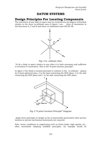
  • 1. Design for Manufacture and Assembly Datum Systems 235 DATUM SYSTEMS Design Principles For Locating Components The movement of any body in space may be resolved into six degrees of freedom relative to the three co-ordinate axes in figure 1,viz., three of translation in the directions X, Y and Z and three co-ordination axes OX OY OZ. Fig.1 Co- ordinate Axes To fix a body in space relative to any other it is both necessary and sufficient to introduce 6 constraints. This is the “6 point location principle”. In figure 2 the block is located precisely in relation to the co-ordinate planes by 6 hemi-spherical pins, 3 in the base contacting the XOY plane, 2 in the side contacting the ZOY plane and 1 in the side contacting the ZOY plane. Fig: 2 “6 point Location Principle” Diagram Apply these principles in design as far as practicable particularly when precise location or precise mechanical movements are required. Note: severe conditions in engineering such as heavy loads, high speeds, etc., often necessitate adopting modified principles. An example would be
  • 2. Design for Manufacture and Assembly Datum Systems 236 substitution of limited areas of contact for the point contact in figure 2 such as is often adopted in jig and fixture design. the point contact in figure 2 such as is often adopted in jig and fixture design. Fig- 3. Datum Spigot and Recess Assembly When locating one component relative to any other in an assembly, design so as to confine the need for positional accuracy to the minimum number of features, consider datum systems. Function of Datum Systems To align certain features on two components in accurate geometric relation when assembled. In the flange coupling, figure 3, a spigot B and recess A have been introduced in the design so as to align the respective shafts on assembly. To locate mating components accurately to finite assembly facilitates assembly. In figure 3 the datum spigot and recess also facilitates assembly of the securing bolts. To set as a convenient base from which to dimension other features. see surfaces A and D is figure 4
  • 3. Design for Manufacture and Assembly Datum Systems 237 Fig: 4 Datum Based Dimensioning Common Datum Systems Group of two or three datum planes Function The system using two co-ordinate planes controls the relative movement of two components in 5 degrees of freedom, while that using three co-ordinate planes controls them in all 6 degrees of freedom. Geometric analysis Geometry involved is flatness and squareness of the planes. Location accuracy This is limited by the tolerances for flatness and squareness. The common is where one plane, usually in largest , is the principal datum, and in others are referred to this for squareness. see figure 5 where X is the principal datum. yy x z Fig: 5 Locational Accuracy of Principal Datum(X) Tolerances Assign flatness tolerances to each principal datum, and squareness tolerances to the other datums relative to the principal. X Z
  • 4. Design for Manufacture and Assembly Datum Systems 238 Note: sometimes it may be necessary to assign special requirements to the flatness tolerance such as “surface must not be convex”, the latter to ensure no rock when assembled. Grouped datum plane and spigot assembling with Grouped datum plane and recess. Fig: 6 . Positional Datum Groups Function This system controls the movement of one component relative to the other in 5 degrees of freedom. The 6th degree not controlled by the system is rotation about OZ. The two planes control 3 degrees of freedom. Viz., translation in the Z direction, and rotation about OX and OY; the spigot and recess control 2 degrees of freedom, viz., translation in the X and Y directions. This system is used as a datum group for position, concentricity or symmetry. Geometric analysis The planes are the principal datums with zero position tolerance. The spigot and recess are the datums with zero position and squareness tolerances all on MMC, relative to the principal datums. Design the spigot short in length since a long spigot introduces redundancy by restraining rotational freedom about OX and OY,which is the function of the planes. Location accuracy This is limited only by the fit C between the spigot and recess and the flatness
  • 5. Design for Manufacture and Assembly Datum Systems 239 DIA 1 Group No .001 DIA Magnitude Geometry Tols MMC No of Features 1B (a) Feature Letter POSN &SQ Type Datum Features A Y -0.304 25.4B O A of the planes. _ Take as criterion C=C±k where C is the mean fit and k is the permissible variation. Basic size Choose this from data sheets as appropriate. Fit, Design sizes and Tolerances The fit between spigot and recess should be chosen to suit the location accuracy required. Confine the choice to the fits given in data sheets. Do not specify flatness tolerances for the planes unless unusually precise location is required. Drawing practice Show the spigot and plane as one geometric group, and the recess and plane as another. See figure 7 and use tabular method (a) in general; Method (b) may be used if there is only one positional groups Geometric Groups and Tolerances
  • 6. Design for Manufacture and Assembly Datum Systems 240 (b) Fig: 7 (a) Tabular Method (b) sketch for Using one positional Groups Example, figure 6 Design requirements Location accuracy to be for translation 0.0254mm Basic size for recess and spigot 25.4mm from data sheet Fit 1.01H8h8 from data sheet giving Recess: 25.4+0.0305 And spigot: 25.4-0.0305 Location accuracy is 0.0305± 0.0305 This is close enough to the design requirement to be satisfactory. Grouped Datum Plane , Spigot and Hole assembling with Grouped Datum Plane, Recess and Pin. See figure 8. Function This system controls the relative movements of two components in all 6 degrees of freedom, but rotation about OZ less precisely than the others. This system is used mainly as a datum group for positional features. Geometric analysis The planes are principal datums with zero position tolerances. The spigot and recess are datums with zero position and squareness tolerances on MMC relative to the principal datums.
  • 7. Design for Manufacture and Assembly Datum Systems 241 Fig:8 Spigot & Hole with Recess & Pin Assembly (Grouped The hole and pin are datums having position and squareness tolerances MMC relative to the datum spigot and plane and the datum spigot and plane and the datum recess and plane Design spigot short in length for the same reason as in 3.22 above. Location accuracy Translational movement in the X, Y and Z directions is limited by the fit C between the spigot and recess and by the flatness of the planes. Take as before the criterion. _ C=C±k Rotation about OX and OY is limited by the flatness of the planes, about OZ by the fit between the spigot and recess and the hole and pin. The clearance between the latter including provision for the position tolerances for the position tolerances for the hole and pin. Take as criterion the mean angular play.ie, at minimum material conditions with no positional errors present.
  • 8. Design for Manufacture and Assembly Datum Systems 242 Geometric Groups and Tolerances. 1 Group No 0.1 dia O dia Magnitude Geometry Tols MMC No of Features 1B C 1 Feature Letter POSN &SQ POSN &SQ Type Datum Feature A Fig: 9 (a) 9(b) Examples.-Grouped Datum Planes with spigot and Hole Assembly Basic Sizes Choose from data sheets as appropriate. Fits, design Sizes and Tolerances The fit between the spigot and recess should be chosen to suit the location accuracy required. Confine your choice to the fits shown in data sheets 4,5 and 6 for Hole basis; Hole Basis is preferred. Do not specify flatness tolerances for the planes unless unusually location is X Y22.0T.P A 25.000 5.000 DIA C +.075 Datum Face A POSN & SQ TOL O dia MMCdia B +0.003 POSN & SQ TOL 0.1 dia MMC Datums Spigot B MMC & Face A. 5.000 DIA +.075 22.0T. Y C X +0.003 25.000 dia B A
  • 9. Design for Manufacture and Assembly Datum Systems 243 required. The fit between the hole and pin must satisfy the location accuracy required and also provide sufficient C min to allow for position tolerances. Confine your choice of fit to those given for positional fits in data sheets; the shaft basis will be applicable here. Drawing practice Show the plane, spigot and hole as one geometric group, with the plane as principal datum for the group. See figure 9(a). Similarly the plane would be shown as principal datum for the recess and the pin in the other component. The tabular method (a) in figure 9 is preferred in general; method (b) may be used if there is only one positional group other than the datum group. Example. Fig:10.Spigot & Hole with Recess & Pin Assembly (Grouped Datum Planes) Design requirements: Location accuracy to be For translation 0.03 0.03mm For rotational 40 minutes of arc Basic size, For recess and spigot 25.0mm For pin and hole 5.0mm
  • 10. Design for Manufacture and Assembly Datum Systems 244 Both from data sheet Choose hole basis for both fits. Assign position tolerances as follows: For spigot 0 dia MMC For hole 0.15 dia MMC For recess 0 dia MMC For hole for pin 0.15 dia MMC For concentricity Of two dies of pins 0.04dia MMC Cmin for spigot and recess =0+0.10 =0 For hole and pin = 0.15+0.15+0.04+0.04 = 0.38 Provisional design sizes are as follows: Recess=25.0: spigot=25.0 Pin = 5.0-0.38: hole = 5.0 =4.62 Choose fits from data sheet as follows: Spigot and recess = 25.0 H8h9 Giving recess 25.000+0.033 And spigot 25.000-0.033 And hole and pin 5.0 H7h9 Giving hole 5.000+0.075 And pin 4.73-0.03 The location accuracy for translation =0.033+/-0.033 This is regarded as satisfactory. The maximum angular play =(5.075-4.700)+(25.033-24.963)*10800/n =69 minutes of arc. Criterion for location accuracy is therefore 35 minutes of arc approximately and hence is satisfactory. The position tolerances for the pin and the corresponding hole would be modified to suit the new Cmin 0.21let position tolerance For hole =0.1 dia MMC For pin =0.1 dia MMC For concentricity of two diameters of pin= 0.01dia MMC And let C=0.03 See figure 9 Grouped Datum Plane, Spigot and Tongue,
  • 11. Design for Manufacture and Assembly Datum Systems 245 Assembling with Grouped Datum Plane, Recess and Gap. (Fig 11) Fig: 11. Spigot & Tongue Assembling with Recess and gap (Grouped Datum Planes) Function This system performs a similar function to 3.3 above, except that rotation about OZ can be more precisely controlled. Geometric Analysis For the planes, spigot and recess same remarks apply as in 3.32. The tongue and gap are also datum related to the other datums, but tolerances are assigned for symmetrically and squareness instead of for position and squareness. Location Accuracy In principle the same remarks apply as in 3.3. Basic sizes Choose from data sheets as appropriate Fits, Design sizes and Tolerances In principle the same remarks apply as in 3.3 above, except that the symmetry tolerance for the tongue relative to the spigot or for the gap relative to the
  • 12. Design for Manufacture and Assembly Datum Systems 246 recess can be small, even zero on MMC.This requirement is much easier to attain with this design than with the corresponding position tolerances in section 3.3. Confine your choice of fit to those given in data sheets for hole basis; another data sheet for shaft basis; hole basis is preferred Drawing practice Show the plane, spigot and tongue as one geometric group with the plane as principal datum for the group see figure 9(a). Similarly the plane would be shown as the principal datum for the recess and pin other geometric group. The tabular method (a) in figure 9 is preferred in general; Method (b) may be used if there is only one positional group other than the datum group. . Fig 12(a) Fig 12 (b)
  • 13. Design for Manufacture and Assembly Datum Systems 247 Grouped Datum Plane and Pins assembling with Grouped Datum Plane and Holes. See Figure 13 Fig 13 Grouped Datum Plane and Pins assembling with Grouped Datum Plane and Holes Function This system controls the relative movements of the two components in all 6 degrees of freedom and in principle relation as precise as translation. The two planes control 3 degrees of freedom viz. Translation in X and Y directions and rotation about OZ. Datum planes Datum pins O Datum plane X Y O Datum holes 1.2 TP Y Z 2 Holes 0.21500±0.0009 dia X Z
  • 14. Design for Manufacture and Assembly Datum Systems 248 Fig :14 Tabular method. Plane as datum for pins Geometric Analysis The planes are principal datums with zero position tolerances. The pins and holes are datums with position and squareness tolerances on MMC related to their respective principal datums. Location Accuracy Translation in the Z direction and rotation about OX and OY is limited by the flatness of the datum planes. Translation in the X and Y directions and rotation about OZ is limited by the fit between the holes and pins the clearance between the later including provision for the position tolerances for the holes and pins. Take as criterion the mean angular play calculated as half the maximum angular play ie at minimum material conditions with no positional errors present. Magnitude 2 Holes 0.21500±0.0009 dia 1.2 TP No of Features Letter Group No B 1 2 POSN &SQ .001 DIA Geometric Groups & Tolerances Feature Geometry Tols MMC Type 2.9 TP A 1.2 TP 2 Holes 0.21500±0.0009 dia A Datum Feature 2.9 TP A
  • 15. Design for Manufacture and Assembly Datum Systems 249 Basic Sizes Choose from data sheets 2 or 3 as appropriate. Fits, Design Sizes and Tolerances Do not specify flatness tolerances for the planes unless unusually precise location is required. The fits between the holes and pins must satisfy the location accuracy required and also provide sufficient Cmin to allow for position tolerances . Assign the same position tolerances to each pin and to each hole. Confine your choice to the positional fits in data sheets 4 and the shaft basis may well be applicable here see data sheet 7. Drawing practice Show the plane and the two holes as one geometric group with the plane as datum for the group. see figure 14similarly the plane would be shown as datum for the pins in the other geometric group. The tabular method (a)in Figure 1.14is preferred in general method (b) may be used if there is only one positional group other than the datum group. Example, Figure 14 Design Requirement Location accuracy to be for rotation of 3 minutes of arc Basic size for pins and holes 6.35mm from data sheet2 Fit (on shaft basis)6.35 h8c9 from data sheet 7 giving pin 6.35 -- .0009 and hole 6.4262 + .0014 Cmin =.003 permitting .0015 dia MMC position tolerances for the pins and the holes. The maximum angular play =(.00531.5) x(10.800/Ď€) =12 minutes of are approx. Criterion for location accuracy is 6 minutes of arc and this is too great in relation to the design requirement. Choose fit (on shaft basis) as 6.35 h8E8 from data sheet 7 giving pin 6.35 -- .0009 And hole 6.4262 + .0009 The maximum angular play =(.00281.5) x (10.800/Ď€) =6.5 minutes of are approx. Criterion for location accuracy is thus 3.25 minutes of arc and in this case is regarded as satisfactory. Cmax = -.001 Position tolerances for strict interchangeability would be .005 dia but are considered to be too small. If we choose .001 dia MMC position tolerances for both the pins and the holes the virtual sizes of pin and hole become secured and then drilled and reamed for the insertion of dowels, which are normally a press fit.
  • 16. Design for Manufacture and Assembly Datum Systems 250 If the cover Figure 1.13 were dealt within this way a suitable note would be inserted on the management drawing such as in figure 1.14. The t chosen here is 6.35h8s7. The holes B would then not ensure strict interchangeability between components but is an economical solution for small to medium Pin .251and Hole .250 Thus theoretically giving interference. However the metal interference will be only on one side of each pin and hole and will not be greater then .0005 Hence the fits and tolerances chosen are regarded as satisfactory. Use of Dowels This system is similar in design to the datum system of section 3.5 However the dowels generally play no part in the control during production. Usually the components are assembled together adjusted quantity production. Fig 15: Tabular method. Plane as datum for pins In the datum systems described in section 3 above the principal datum was invariably the plane or at surface and the spigot was made short in length to ensure that its function did not conflict with that of the planes. In same cases however such as in figure 15 the shaft may be used to align the component on assembly and is then made for the better to achieve this function. The shaft becomes the principal datum in the datum system and the surface Y is tolerenced for squareness in relation to Z as shown in figure 15. A shaft washer is inserted under the head so ads to provide for errors in squareness.. Magnitude 2 Holes 0.21500±0.0009 dia 1.2 TP No of Features Letter Group No B 1 2 POSN &SQ .001 DIA Geometric Groups & Tolerances Feature Geometry Tols MMC Type 2.9 TP A 1.2 TP 2 Holes 0.21500±0.0009 dia A Datum Feature 2.9 TP A