Mastering MySQL Database Architecture: Deep Dive into MySQL Shell and MySQL R...
Internal combustion engine power plant
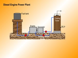
1. Diesel Engine Power Plant
Fuel tank
Engine
Generator
Cooling
Tower
Fuel
Pump
Cooling Water
Pump
Air in
Air out
2. Four-Stroke Cycle Engine: An engine that completes one cycle in two
revolutions of the camshaft.
Intake
Compression
Power
Exhaust
intake compression power exhaust
3. Two-Stroke Cycle Engine: An engine that completes one cycle in one
revolution of the camshaft.
Intake & Compression
Power & Exhaust
Exhaust port Exhaust port
Intake port Intake port
Intake & Compression Power & Exhaust
4. Engine Performance
1. Heat Supplied by Fuel (QS)
QS = mF x HV KJ/hr
Where: mf – fuel consumption in kg/hr
HV – heating value of fuel in KJ/kg
KW
4(60)
Nn'LDP
IP
2
miπ
=
2. Indicated Power (IP)
Where: Pmi – indicated mean effective pressure, KPa
L – length of stroke, m
D – diameter of bore, m
N = (RPM)/2 For 4-stroke single acting
N = (RPM) For 4-stroke double acting
N = (RPM) For 2-stroke single acting
N = 2(RPM) For 2-stroke double acting
5. KW
4(60)
Nn'LDP
BP
2
mbπ
=
3. Brake Power (BP)
KW
60,000
TN2
BP
π
=
Where: Pmb – brake mean effective pressure, KPa
L – length of stroke, m
D – diameter of bore, m
N = (RPM)/2 For 4-stroke single acting
N = (RPM) For 4-stroke double acting
N = (RPM) For 2-stroke single acting
N = 2(RPM) For 2-stroke double acting
Where: T – brake torque in N-m
N – no. of (RPM)
6. 4. Friction Power (FP)
FP = IP - BP
5. Indicated Mean Effective Pressure (Pmi)
KPa
L'
SA'
Pmi =
Where: A’ – area of indicator card, cm2
S – spring scale, KPa/cm
L’ – length of indicator card, cm
6. Brake Torque (T)
T = (P – tare)R N-m
Where: P – gross load on scale, N
tare – tare weight, N
R – length of brake arm, m
7. 7. Piston Speed (PS)
PS = 2LN m/min
8. Displacement Volume (VD)
sec
m
P
BP
V
sec
m
P
IP
V
sec
m
4(60)
Nn'LD
V
3
mb
D
3
mi
D
32
D
=
=
π
=
9. Specific Fuel Consumption
a. Indicated Specific fuel consumption
hr-KW
kg
IP
m
m F
fi =
8. b. Brake Specific fuel consumption
hr-KW
kg
BP
m
m F
fb =
c. Combined Specific fuel consumption
hr-KW
kg
GP
m
m F
fc =
Where: GP – Generator power
10. Heat Rate (HR)
a. Indicated Heat Rate (HRi)
hr-KW
KJ
IP
Q
HR S
I =
9. b. Brake Heat Rate (HRb)
hr-KW
KJ
BP
Q
HR S
b =
c. Combined Heat Rate (HRc)
hr-KW
KJ
GP
Q
HR S
c =
11. Generator Speed (N)
RPM
n
120f
=N
Where: n – number of generator poles (usually divisible by 4)
10. 12. Mechanical Efficiency (ηm)
100%x
BP
GP=gη
100%x
IP
BP=mη
13. Generator Efficiency (ηg)
14. Indicated Thermal Efficiency (ei)
100%x
Q
3600(IP)
e
S
i =
15. BrakeThermal Efficiency (eb)
100%x
Q
3600(BP)
e
S
b =
11. 16. Combined Thermal Efficiency (ec)
100%x
Q
3600(GP)
e
S
c =
17. Indicated Engine Efficiency (ηi)
100%x
e
ei
i =η
18. Brake Engine Efficiency (ηb)
100%x
e
eb
b =η
19. Combined Engine Efficiency (ηc)
100%x
e
ec
=η
Where: e – cycle thermal efficiency
12. 20. Volumetric Efficiency (ηv)
100%x
VolumentDisplaceme
ndrawnairofvolumeActual
ηv =
s
h
h
s
sh
T
T
B
B
PP =
21. Correction Factor for Non Standard Condition
Considering Pressure and Temperature Effects
Considering Temperature Effects alone
s
h
sh
T
T
PP =
13. Considering Pressure Effects alone
h
s
sh
B
B
PP =
Note: From US Standard Atmosphere
K
1000
6.5h
-TT
Hgmm
1000
83.312h
BB
sh
sh
°=
−=
Where:
P – power, KW
B – pressure, mm Hg
T – temperature,°K
h – elevation, meters
Subscript:
s – refers to sea level
h – refers to the elevation
14. ENGINE HEAT BALANCE
Qs = Q1 + Q2 + Q3 + Q4
Where:
Q1 – heat converted to useful work
Q2 – heat loss to cooling water
Q3 – heat loss due to exhaust gases
Q4 – heat loss due to friction, radiation and unaccounted for
Q1 = 3600(BP) KJ/hr
Q2 = mwCpw(tw0 – tw1) KJ/hr
Q3 = Qa + Qb
Qa = mgCpg(tg – ta) KJ/hr
Qb = mf(9H2)(2442) KJ/hr
Q4 = Qs – (Q1 + Q2 + Q3) KJ/hr