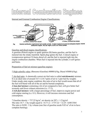
1. Internal and External Combustion Engine Classifications:
Gasoline and diesel engine classifications:
A gasoline (Petrol) engine or spark ignition (SI) burns gasoline, and the fuel is
metered into the intake manifold. Spark plug ignites the fuel. A diesel engine or
(compression ignition Cl) bums diesel oil, and the fuel is injected right into the
engine combustion chamber. When fuel is injected into the cylinder, it self ignites
and bums.
Preparation of fuel air mixture (gasoline engine):
* High calorific value: (Benzene (Gasoline) 40000 kJ/kg, Diesel 45000 kJ/kg).
* Air-fuel ratio: A chemically correct air-fuel ratio is called stoichiometric mixture.
It is an ideal ratio of around 14.7:1 (14.7 parts of air to 1 part fuel by weight).
Under steady-state engine condition, this ratio of air to fuel would assure that all of
the fuel will blend with all of the air and be burned completely.
A lean fuel mixture containing a lot of air compared to fuel, will give better fuel
economy and fewer exhaust emissions (i.e. 17:1).
A rich fuel mixture: with a larger percentage of fuel, improves engine power and
cold engine starting (i.e. 8:1). However, it will increase emissions and fuel
consumption.
* Gasoline density = 737.22 kg/m3
, air density (at 20o
) = 1.2 kg/m3
The ratio 14.7 : 1 by weight equal to 14.7/1.2 : 1/737.22 = 12.25 : 0.0013564
The ratio is 9,030 : 1 by volume (one liter of gasoline needs 9.03 m3
of air to have
complete burning).
1
2. * Fuel atomization: refers to how the fuel injector or carburetor breaks up liquid
gasoline into tiny droplets.
* Compression of the air-fuel mixture: During this process the pressure and
temperature of the gas rise. The ratio of volume before and after compression is
called the compression ratio:
c
s
c
sc
V
V
V
VV
r +=
+
= 1
where:
r = compression ratio
Vs = Swept volume (cylinder volume),
Vc = clearance volume
Engine swept volume (engine displacement, engine capacity):
nVV se ×=
where:
Ve = Engine swept volume -in liters or cubic centimeters (liter, or cm3
(cc))
Vs = Cylinder swept volume
n = number of cylinders
2
3. Volumetric efficiency (ηv)
Volumetric efficiency
= Volume of air taken into cylinder / Maximum possible volume in cylinder
* Volumetric efficiency depends upon throttle opening and engine speed as well as
induction and exhaust system layout, port size and valve timing and opening
duration.
3
5. Engine cycles
*Two-stroke cycle *Four stroke cycle
Four-stroke-cycle engine:
* Intake (induction or inlet) stroke: The intake valve has opened. The piston is
moving downward, drawing a mixture of air and gasoline vapor into the cylinder.
* Compression stroke: The intake valve has closed. The piston is moving upward,
compressing the mixture.
* Power stroke: The ignition system has delivered a spark to the spark plug that
ignites the compressed mixture. As the mixture burns, high pressure is created
which pushes the piston downward.
* Exhaust stroke: The exhaust valve has opened. The piston is moving upward,
forcing the burned gases from the cylinder.
Two-stroke-cycle engine:
A two-stroke cycle engine is similar to an
automotive four-stroke engine, but it only
requires one revolution of the crankshaft
for a complete power-producing cycle.
Generally, two-stroke cycle engines are
NOT used in automobiles because they:
- Produce much exhaust pollution
- Have poor power output at low speeds
- Require more service than a four-stroke
- Are not as fuel efficient as a four- stroke
- Must have motor oil mixed into the fuel.
5
7. Engine indicator diagrams:
Indicated mean effective pressure (imep):
This is the average pressure acting on the power stroke which creates the same
amount of work as the varying pressure within the engine cylinder acting behind the
piston. imep units are N/m2
, kN/m2
, and the Pascal (N/m2
) could be used.
* The highest mean effective pressure obtained without supercharging, and using
petrol as fuel is between 896 and 1103.6 kPa (kN/m).
7
8. Indicated power (Pi):
This is the power that would be available at the crankshaft if a mechanical
efficiency of 100% was possible. The term “indicated” is derived from the use of
engine indicators and their diagrams from which indicated power could be
calculated.
Total average force per revolution [F] (N or kN) = (imep . A) n /2 (4-stroke cycle)
Total work done per revolution [W] (N m or J, kN m, kJ) = F . L = imep . A n L /2
Total work done per second (power) [P] = J/sec (W) = imep . A n L . (N/2) /60
Indicated power (Pi) [4-stroke cycle] = imep x L A n (N/2) /60 (N m/s) or W
Indicated power (Pi) [2-stroke cycle] = imep x L A n N /60 (N m/s) or W
Where:
imep = average or indicated mean effective pressure (N/m2
) or kN/m2
A = area of the piston crown (m2
)
n = number of engine cylinders
L = piston or engine stroke (m)
N/2 = number of firing impulses per minute per cylinder (4-stroke cycle)
n N/2 = engine number of firing impulses per minute (4-stroke cycle)
n N = engine number of firing impulses per minute (2-stroke cycle)
L A n = total swept volume of engine, or engine capacity (m3
)
P = indicated power (N m/s or W)
Engine friction:
Brake power (Pb):
The brake power (net power) is the engine’s power as measured at the crankshaft at
a specified rpm. The engine brake power is obtained using a brake dynamometer at
engine full throttle.
8
9. Mechanical efficiency (ηm):
Mechanical efficiency (ηm) = brake power (Pb)/indicated power (Pi)
Thus
brake power = ηm . indicated power, (Pb = Pi ηm)
brake power = ηm . imep L A n (N/2) /60 (W)
The pumping losses of the engine pistons, and the friction between their rings and
the cylinder walls, account for the greater part or percentage of the lost work and
power.
The main factors which contribute to the lost power are:
1. the type of materials used and their surface finish;
2. the loading between materials in contact under boundary lubrication conditions;
3. the rubbing speeds.
4. the engine compression ratio;
5. revolution per minute;
6. the throttle position;
7. windage. Air resistance increases in proportion to the square of the speed. The
flywheel, clutch, generator and engine-operated cooling fan all introduce windage;
8. the churning of the lubricating oil.
* From the figure it can be seen that the indicated power (Pi) is somewhat higher
than the brake power (Pb) throughout the rev/min range, but not proportionally
higher. If the vertical distance between the two curves is measured at each
revolution point, this distance will represent the power lost to pumping and friction
at that engine speed (friction power Pf). As engine speed rises so the losses increase,
hence the increasing divergence between the brake power and indicated curve lines.
9
10. Engine torque (Nm):
Torque (T) is a turning moment (N m) and is dependent on the pressure produced
within the engine cylinders, the piston crown area upon which the effective pressure
(bmep) is applied, and the crankshaft angle or effective radius. Engine capacity thus
plays a large part in torque production. Doubling the engine’s capacity (swept
volume Ve) will almost double the engine torque.
When engine testing with a dynamometer, the load lifted is situated at end of the
dynamometer torque arm:
thus torque T = w . R (Nm)
The work done in one revolution is calculated as follows (see figure). If the brake
load w was moved through one revolution (2π) 3600o
with the radius or torque arm
of R (m), the work done in one revolution:
W = w . π R (N m) or J
= T . 2π (N m) or J
where:
T = w . R
Torque and the crankshaft angle
Work is also accomplished when the torque is applied through an angle. Distance
xy (see figure, is equal rθ) where θ is the angle through which the crankshaft
moves, in radians.
torque = force . radius =F. r
work done = F . distance xy =F . r θ = T . θ
work done per one revolution (2π) = T . 2π (J) or N m
10
11. Engine brake power (Pb):
This is the power developed at the crankshaft or flywheel. The term brake
originated from the method used to determine an engine’s power output by
measuring the torque using some form of friction dynamometer. In early days of
engine design the flywheel was often used for the brake dynamometer. Often
quoted brake power figures do not indicate whether they are gross or net.
An engine connected to a modern test bench is generally without such items as
cooling fan, coolant pump and radiator, dynamo and clutch unit and is connected to
the large test bench exhaust system. Thus some 10-15% more power is often
possible under these conditions (gross power) compared to the ‘under the bonnet’
performance (net power).
* On the Continent, the DIN rating is used, which confirms the engine’s
performance with all its accessories as fitted to the chassis together with correction
for normal temperature and pressure. in the USA the SAE rating method is adopted
which in effect is the gross engine output.
11
12. Power is the rate of doing work = work done/time taken (Joules/sec) or Watts
= force . distance / time taken (t seconds)
= F . xy/t =F . rθ/t =T . θ/t = Tω
Note:
ω = θ/t = angular velocity in radians/second = 2πN/60
where:
N = engine rev/min
Brake power per one revolution = Work done per one revolution =T 2π
Work done was previously stated as equal to (imep ηm LAn/2) therefore
T 2π = (imep ηm) LAn/2
T = . LAn/4π = (imep ηm). engine swept volume / 4π
also brake power Pb = Tω =T . 2πN/60 = (imep ηm) . LAnN/(60 . 2)
Pb = bmep . engine swept volume . number of effective stroke / s
* indicated power = brake power + friction power
Pi = Pb + Pf
Mechanical efficiency % = ηm = brake power/indicated power = (Pi/Pb) . 100 %
* bmep (imep ηm) is an indication of engine efficiency regardless of capacity or
engine speed; 1000 kPa represent high efficiency.
Fuel consumption and thermal efficiency:
The fuel an engine consumes can be measured by volume or by mass. By volume
the units are cm liters per second, minute or hour (1000 cm = 1 liter). By mass the
units are kg per second, minute or hour (1 liter of water = 1 kg).
Liters x relative density of the fuel = kg of fuel
Specific fuel consumption (SFC):
Specific fuel consumption represents the mass or volume of fuel an engine
consumes per hour while it produces 1 kW of power. It is an indication of the
engine’s thermal or heat efficiency and is one of the most important engine
characteristics. Comparisons can be made between engines of widely different
capacities and characteristics, providing similar fuel and test conditions are
arranged for each test.
A mirror reflection of the specific consumption curve shows the shape of the
engine’s thermal efficiency curve. The lowest point on the consumption curve
becomes the highest point on the thermal efficiency curve.
If the consumption = kg/(kW h), (h = hour)
=(kg/h)/kW or L/(kW h)
12
13. SFC = (mass of fuel consumption/h) / engine brake power
SFCi = (mass of fuel consumption/h) / engine indicated power
* Motorists assess fuel consumption in terms of kilometer per liter (km/L),
(mile/gallon)
Thermal efficiency (ηth):
The efficiency of an engine in converting the heat energy contained in the liquid
fuel into m energy is termed its thermal efficiency. A study of the results taken from
heat balance tests shows clearly that internal combustion engines are inefficient at
this conversion. The petrol engines particularly inefficient and at its best may reach
25% efficiency.
CV.(kg/h)
P
powerfuel
powerbrake
units)(heatinput
units)(heatoutput
efficiencythermalbrake b
===
where: CV is the calorific or heat value of 1 kg of the fuel (J/kg, kJ/kg or MJ/kg).
CV.ρ.(L/h)
P3600
)(ηefficiencythermalbrake
CV.(kg/h)
.6060.P
)(ηefficiencythermalbrake
b
th
b
th
=
=
where ρ is the relative density (kg/L) of the fuel.
13
15. Factors affect the engine torque and power:
Pre -ignition, detonation, retarded ignition, weak mixture, engine load, piston
speed, ignition timing, camshaft advanced or crankshaft retarded, tappet clearances,
variation of compression ratio, fuel pump injection timing, supercharging.
15
16. Power to weight ratio (single-and multi-cylinder engines):
The engine power varies as the square of the bore (piston area) but the mass varies
as the square of the bore (that is with the volume used). Increasing power by using a
large cylinder therefore results in a low power/weight ratio, where as increasing the
number of cylinders maintains power to weight in the same proportion.
16