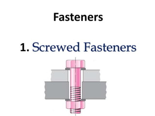
2. Introduction
A machine element used for holding or joining two or more parts of a
machine or structure is known as a fastener.
The fasteners are of two types : permanent and removable (temporary).
Riveting and welding processes are used for fastening permanently.
Screwed fasteners such as bolts, studs and nuts in combination, machine
screws, set screws, etc., and keys, cotters, couplings, etc., are used for
fastening components that require frequent assembly and dissembly.
In general, screwed fasteners are used :
(i) To hold parts together,
(ii) To adjust parts with reference to each other and
(iii) To transmit power.
3. Screw Threaded Nomenclature
A screw thread is obtained by cutting a continuous helical groove on a cylindrical
surface (external thread). The threaded portion engages with a corresponding
threaded hole (internal thread); forming a screwed fastener.
4.
5. Other thread profiles
Apart from ISO metric screw thread profile, there are other profiles in use to meet various
applications, the characteristics and applications of which are discussed below :
V-Thread
• This thread profile has a larger contact area, providing more frictional resistance to
motion. Hence, it is used where effective positioning is required. It is also used in brass
pipe work.
British standard Withworth(BSW) Thread – less sensitive to damage than V-Thread
Buttress thread
• This thread is a combination of V-and square threads. It exhibits the advantages of square
thread, like the ability to transmit power and low frictional resistance, with the strength
of the V-thread. It is used where power transmission takes place in one direction only
such as screw press, quick acting carpenter’s vice, etc.
6. Cont…
Square-Thread
• Square thread is an ideal thread form for power transmission. In this, as the thread flank is
at right angle to the axis, the normal force between the threads, acts parallel to the axis,
with zero radial component. This enables the nut to transmit very high pressures, as in the
case of a screw jack and other similar applications.
ACME - Thread
• It is a modified form of square thread. It is much stronger than square thread because of the
wider base and it is easy to cut. The inclined sides of the thread facilitate quick and easy
engagement and disengagement
7. Thread Designation
• The diameter-pitch combination of an ISO metric screw thread is designated by the letter
‘M’ followed by the value of the nominal diameter and pitch, the two values being
separated by the sign ‘×’.
• For example, a diameter pitch combination of nominal diameter 10 mm and pitch 1.25
mm is designated as M10 × 1.25. If we given, M 10 means that the nominal diameter of the
thread is 10 mm and pitch is 1.5 mm.
Following are the other designations, depending on the shape of the thread profile :
• SQ 40 × 10 – SQUARE thread of nominal diameter 40 mm and pitch 10 mm
• ACME 40 × 8 – ACME thread of nominal diameter 40 mm and pitch 8 mm
8.
9. Multi Start Thread
• A single-start thread consists of a single, continuous helical groove for which
the lead is equal to the pitch. As the depth of the thread depends on the pitch,
greater the lead desired, greater will be the pitch and hence smaller will be the
core diameter, reducing the strength of the fastener. To overcome this
drawback, multi-start threads are recommended.
11. Representation of Threads
• The true projection of a threaded portion of a part consists of a series of helices
and it takes considerable time to draw them. Hence it is the usual practice to
follow some conventional methods to represent screw threads.
• It may be noted from Fig., that the crests of threads are indicated by a
continuous thick line and the roots, by a continuous thin line.
14. Method of Drawing Hexagonal (Bolt Head) Nut
The following approximate methods are used to save the drawing time
Empirical relations :
Major or nominal diameter of bolt = D
Thickness of nut, T = D
Width of nut across flat surfaces, W = 1.5D + 3 mm
Radius of chamfer, R = 1.5D
15. Method of Drawing Square (Bolt Head) Nut
Major or nominal diameter of bolt = D
Thickness of nut, T = D
Width of the nut across flats, W = 1.5 D + 3 mm
Radius of chamfer arc, R = 2 D
22. Assignment-6
1. Draw the necessary view of Hexagonal Bolt dia. 60mm, nut and its washer
2. Draw the following the necessary view of Eye-Foundation Bolt of diameter 50mm.
24. Riveted Joint
• Riveted joints are permanent fastenings and riveting is one of the commonly
used method of producing rigid and permanent joints. Manufacture of boilers,
storage tanks, etc., involve joining of steel sheets, by means of riveted joints.
Rivet
A rivet is a round rod of circular cross-section. It consists of two parts, head and
shank
Mild steel, wrought iron, copper and aluminum alloys are some of the metals
commonly used for rivets.
Riveting
Riveting is the process of forming a riveted joint. For this, a rivet is first placed in
the hole drilled through the two parts to be joined. Then the shank end is made
into a rivet head by applying pressure, when it is either in cold or hot condition.
29. Dimensions
The size of the rivet, d is taken as, where ‘t’ is the thickness of the plates to be
joined in millimeters.
Row Pitch:
It is the distance between two adjacent rows of rivets. It is denoted by ‘pr’ and is given by,
pr = 0.8p, for chain riveting pr = 0.6p, for zig-zag riveting.
Margin
It is the distance from the edge of the plate to the centre of the nearest rivet. It is usually taken
as 1.5d, where d is the rivet diameter. It is denoted by ‘m’.
30. In a single strap butt joint, the thickness of the strap (cover plate) is given by,
t1 = 1.125t
If two straps are used, the thickness of each cover plate is given by, t2 = 0.75t
31. Keys and Pin joints
Keys and pin joints are some examples of removable (temporary) fasteners.
Keys
Keys are machine elements used to prevent relative rotational movement between a
shaft and the parts mounted on it, such as pulleys, gears, wheels, couplings, etc.
32. Keys are classified into three types: saddle keys, sunk keys and round keys.
Saddle keys
33. Sunk Keys
If D is the diameter of the shaft, then,
Width of key, W = 0.25 D + 2 mm
Thickness of key, T = 0.67 W (at the thicker end)
Standard taper = 1:100
Height of head, H = 1.75 T
Width of head, B = 1.5 T
36. Pin Joint
In a pin joint, a pin is used to fasten two rods that are under the action of a tensile force;
although the rods may support a compressive force if the joint is guided. Some pin joints
such as universal joints, use two pins and are used to transmit power from one rotating
shaft to another
Knuckle Joint